Page 1001 of 1413

Dashboard
Component Removal/lnstallation (cont'dl
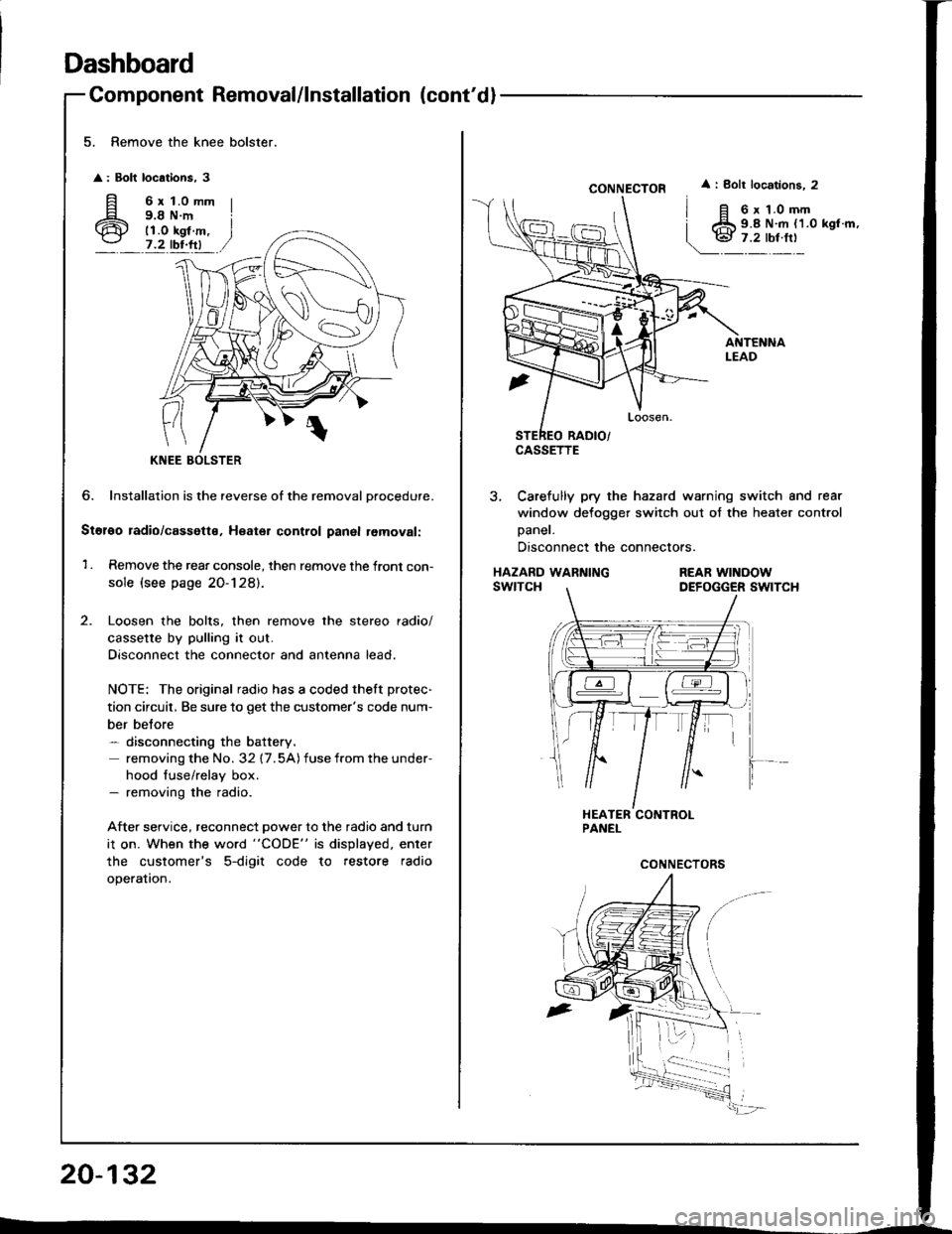
5. Remove the knee bolster.
: Bolt locations, 3
fi 6rt.omm
6 i;i'i#.,7.2 tbr.ftl
?
KNEE
6. Installation is the reverse of the removal Drocedure.
Stol€o radio/cassette, Heater control panal removal:
1 . Remove the rear console, then remove the front con-
sole (see page 20-128).
Loosen the bolts, then remove the stereo radio/
cassette by pulling it out.
Disconnect the connector and antenna lead.
NOTE: The original radio has a coded theft protec-
tion circuit, Be sure to get the customer's code num-
ber belore- disconnecting the battery.
removing the No. 32 17.5A) fuse from the under-
hood fuse/relay box.- removing the radio.
After service, reconnect power to the radio and turn
i1 on. When the word "CODE" is displayed. enter
the customer's 5-digit code to restore radio
operation.
20-132
CONNECTOR
CASSETTE
i Bolt locations. 2
6 x 1.0 mm9.8 N.m {1.0 kgl.m,
3, Carefully pry the hazard warning switch and rear
window defogger switch out of the heater control
Daner.
Disconnect the connectors.
HAZARD WARNINGswtTcHREAR WINOOWDEFOGGER SWITCH
Page 1002 of 1413
4. Remove the screws.
Detach the harness clip and connector clip.
> : Screw locations, 2
Disconnect the air mix control cable from the heat-
er unrt.
AIR MIX CONTROLCABLE
AIR MIX CONTROL
CONNECTOR CLIP
HEATER CONTROL
CABLE
20-133
Pull the heater control panel out, then disco.rEt rhGconneclors.
NOTE: Take care not to bend the atr mtx controlcable.
AIR MIX COI{TROLCABLE
HEATERCONTROIPANEL
7, lnstallation is the reverse o{ the removal procedure.
NOTE: Make sure the connector and air mix con-trol cable are connected properly.
(cont'd)
Page 1037 of 1413

Heater and Air Conditioning
Heater ........ 21-1
Air Conditioning .......... ..22-1
SUPPLEMENTAL RESTRAINT SYSTEM {SRS}
The Integra SRS includes a driver's airbag, located in the steering wheel hub. In addition. all models except the
RS model for Canada have a front passenge.'s airbag located in the dashboard above the glovs box. Information
necessary to safely service the SRS is included in this Service Manual. ltems msrk€d with an asterisk (') on the
conlents page include, or are located near, SRS components. Servicing, disassembling or,eplacing thes€ items
will require special precautions and tools, and should therefore be done by an authorized Acura dealer.
a To avoid r6nd6dng tho SRS inoporativo. which could lead to personal injury or dealh in tho svont ot a sevele
frontal collision, all SRS servica work musl b€ portormed by an authorized Acura dealer.
a lmpropor sorvico procaduro3, including incorrect romoval and installatlon of tho SRS, could load to porsonal iniu-
ry causod by uninlonlional activation of tho ailbag8.
a All SRS eloctdcal widng harnossos are covored with yollow in3ulation. Relatsd compononts a.o locatod in tha
stsering column, flont console, daehboard, and dashboafd low6r pan6l, and in lhe dsshboa.d above lh€ glove
box. Do not uao electdcal tost equipmont on theae circuhs.
NOTE: The original radio has a coded theft protection circuit. Be sure to get the customer's code number beto.e
- disconnecting the battery.- removing the No. 32 (7.5 A) luse from the under-hood fuse/relay box.- removing the radio.
After service, reconnect power to the radio and turn it on. When the word "CODE" is displayed, enter the cus-
tomer's 5-digit code to restore radio operation.
Page 1038 of 1413

Heater
lflustrated Index ............. .........21-2
Heater Door Positions .........,..,. 21-3
Circuit Diagram ....................... 21-6
Troubleshooting
Symptom Chart ............. ......21-8
Flowcharts
Blower Motor Speed ............................... 21 -9
Bfower Motor .........,..,,,,,.. 21-11
Mode Control Moto. ............ ................... 21 -14
Recircufation Control Motor ......,...,.,,,.,.... 21 -17
Heater Control Panel Input/
Output Signals ..............21-19
Blower Unit
Repfacoment ....................... 21-20
Overhaul .......21-21
+Heater Unit
Repfacement ....................... 21-22
Overhaul .......21-24
Def roster Door Adjustment ...,............. ......,, 21 -25
Heatel Control Panel
Repfacoment ....................... 21-25
Overhaul .......21-26
Heater Valve Cable
Adjustment ...21-27
Air Mix Control Cable
Adjustment ... 21-27
Mode Control Motol
Test .............. ..................... 21-2e
Repfacement ..,..............,,,,.. 21-28
Recirculation Control Motor
Test .............. ..................... 21-29
Repfacement ....................... 21-29
Relay
Test .............. ..................... 21-30
Heater Fan Switch
Test .............. ..................... 21-30
Mode Control Switch
Test .............. ..................... 21-31
Recilculation Control Switch
Test .............. ..................... 21 -31
*: Read SRS precautions before working in this area.
Page 1039 of 1413

lllustrated Index
CAUTION:
a All SRS electrical wiling harnesses are covered with
y€llow insulation.
a Bafore disconnecting any pan of the SRS wile har-
ness. connect the sholt connectorlsl.
a Replace the sntire aflected SRS halness assembly if
it has an open circuit or damaged wiring.
NOTE: The original radio has a coded thelt protection
circuit. Be sure to get the customer's code number before- disconnecting the battery.- removing the No. 32 (7.5 Al fuse lrom the under-
hood fuse/relav box.- removing the radio.
After service, reconnect power to the radio and turn it
on. when the word "CODE" is displayed, enter the cus-
tomer's 5-digit code to restore radio operation.
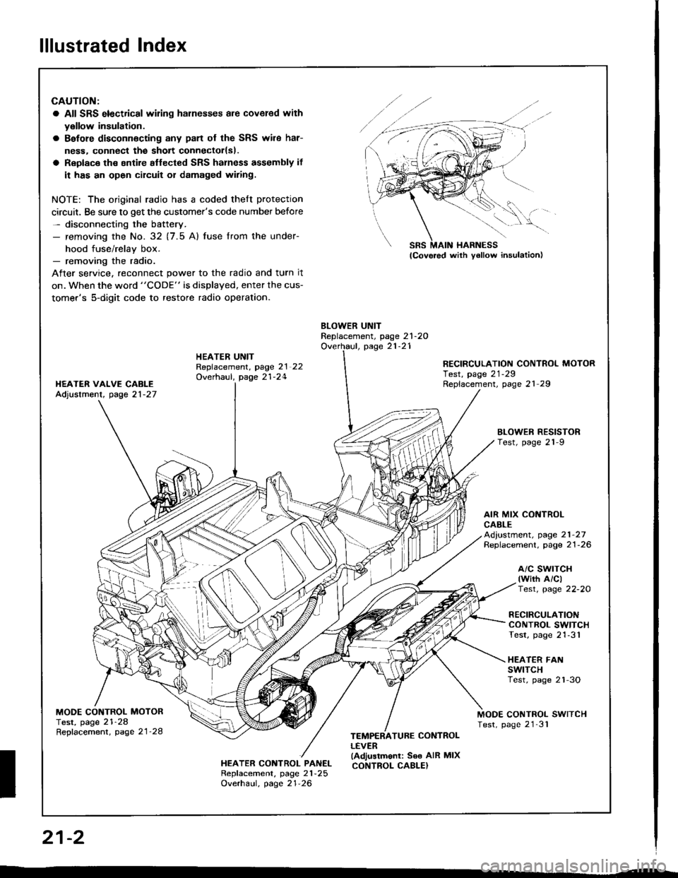
BLOWER UNITReplacement, page 21-2OOverhaul, page 21-21HEATER UNITRepfacement, page 2l 22Overhaul, page 21-24
RECIRCULATION CONTROL MOTORTest, page 21-29Replacement, page 21 29I{EATER VAIVE CABLEAdjustment, page 21-27
BLOWEN RESISTORTest, page 21-9
AIR MIX CONTROLCABLEAd,ustment, page 21-27Replacement. page 21-26
a/c swrTcH(wirh A/clTest, page 22-20
RECIRCULATIONCONTROL SWITCHTest, page 21-31
HEATER FANswtTcHTest, page 2'l-3O
MODE CONTROL MOTORTest, page 21-28Repfacement, page 21'28
MODE CONTROL SWITCHTest, page 21'31
HEATER CONTROL PANELRepf acement, page 21 -25
Overhaul, page 21-26
TEMPERATURE CONTROLLEVER(Adjustmonl: See AIR MIXCONTROL CABLE}
SRS MAIN HARNESS
W,
21-2
I
Page 1040 of 1413
Heater Door Positions
*)
! xorfr coor.
-*)
(HEAT/VENTI
(cont'd)
VENT OOOR
21-3
Page 1041 of 1413
Heater Door Positions
(cont'd)
)
IHEATI
El
IHEAT/DEF)
Page 1044 of 1413
I r.l. A.t tA_ A_r rA. A_r rA. A-l| | I lt I I -lt | -l -f | | -l -lr
rt,/ ,f rr,/ ,/ tt f ,f tt,/ ,f II tv v I rv v I rv v I rv v I
UGHTI GswtTcH
IRED/BI.K
OASH IIGTTTSEnrGFr ESScoNTROU.IT
HEATER CONTROL PANEI.
21-7