Page 954 of 1413

SymptomProbable Cause
Water leaks1. Clogged drain tube.
2. Gap between glass weatherstrip and roof panel.
3. Defective or improperly installed glass weatherstrip.
4. Gap between drain seal and roof panel.
Wind noise1. Excessive clearance between glass weatherstrip and root panel.
Motor noise1. Loose motor.
2, Worn gear or bearing,
3. Cable assembly deformed.
Glass does not move, but motor
turns
1. Clutch out of adjustment.
2. Foreign matter stuck between guide rail and slider.
3. lnner cable loose.
4. Cable assembly not attached properly.
Glass does not move and motor
does not turn {glass can be moved
with moonroof wrench)
1. Blown fuse.
2. Faulty switch.
3, Battery run down.
4. Defective motor.
5. Faulty relay.
Glass Height Adjustment
The roof panel should be even with the glass weather-
strip, to within 1.8 tO.5mm{O.O7 1O.O2 in} allthe way
around. lf not, slide the sunshade back, and:
Tilt-up the glass.
Loosen the bolts and adjust the glass.
Repeat on opposite side if necessary.
ROOF PANELGLASS ERACKET
GLASS WEATHERSTRIP
4. Side-to-side fit of glass weatherstrip can be adjust-
ed by loosening the frame mounting bolts and mov-
ing the frame right or lett and forward or backward
by hand (see page 20-87).
GLASS BRACKETForward
V : Eolt localions, 6
6x LOmm9.8 N.m 11.O kgf m,7.2 tbf.ttt
I
")
1.
2.
GLASS
4'/1210.5 mm lO.O7 1O.02 inl
Page 956 of 1413

Motor, Drain Tube and Frame Replacement
CAUTION: Be carotul not to damago th€ seats, dash-
board and other int6rior trim,
1. Remove the glass (see page 2O-86) and headliner(see page 20-10O).
Disconnect the motor connector, and remove the
clips securing the ceiling light wire harness.
NOTE: To remove the motor, remove the screws.
Disconnect the drain tubes.
Loosen the front bolts.
Remove the bolts, then remove the trame from the
car.
NOTE:
a You may require assistance when removing the
trame.
a Take care not to bend the sunshade rails.
TUBECLIP
DRAIN TUBETo install, slade the drain tube ov6rthe frame nozzle at least 10 mm lO.4 in).
SUNSHADERAILS
Pullthe drain tubes out of the tront and rear oillars.
NOTE: Before pulling out the drain tube, tie a string
to the end of it so it can be reinstalled.
Installation is the reverse of the removal grocedure.
NOTE:
a Install the tube clips with the ends facing the side to easea Clean the surtace of the frame.
a Check the frame seal.
a Check for water leaks.
a Make sure the sunshade moves smoothlv.
SCREW
4.
\/
Make sure the sliders areparallel when installing themotor,
CONNECTOR
FRAME
BOLT6 x 1.0 mm9.8 N.m (1.O lg{.rn.7.2 tbt.ttl
Loosen the tront bohs
Fo?w!?d
tt.
FRONTDRAIN VALVES
installation of the headliner.
20-87
Page 1094 of 1413

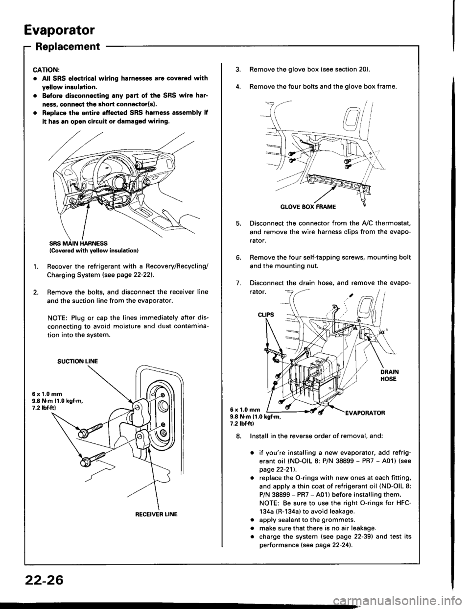
Evaporator
Replacement
CATION:
. All SRS eloctrical wiring harnesses are coverod with
yollow in3ulation.
. B€tore disconnocting 8ny part of tho SRS wire har-
nsss, conngqt th€ 3hort connestor{sl.
. Roplaca ths entire aftected SRS harness a$embly if
it has an op€n circuit or damaged wiring.
lcove.ed with yellow insulation)
Recover the refrigerant with a Recovery/Recycling/
Charging System lsee page 22-22]-.
Femove the bolts, and disconnect the receiver line
and the suction line from the evaporator.
NOTE: Plug or cap the lines immediately after dis-
connecting to avoid moisture and dust contamina-
tion into the svstem.
2.
L
6x1.0mm9.8 N.m {1.019f.m,1.2 tbl.ttl
SUCTION LINE
RECEIVEB LINE
3.Remove the glove box (see section 20).
Remove the four bolts and the glove box frame.
Disconnect the connector from the Ay'C thermostat,
and remove the wire harness clips from the evapo-
rator.
Remove the four self-tapping screws, mounting bolt
and the mounting nut.
Disconnect the drain hose, and remove the evapo-
rator.
1.
6x1.0mmAPORATOR9.8Nm{1.0kg{.m,7.2 tbtft)
a
a
8. Install in the reverse order of removal. and:
it you're installing a new evaporator, add refrig-
erant oil (ND-OIL 8: P/N 38899 - PR7 - A01) (see
page 22-2'll.
replace the O-rings with new ones at each fitting.
and apply a thin coat of refrigerant oil (ND-OlL 8:
P/N 38899 - PR7 - A01l before installing them.
NOTE: Be sure to use the right o-rings for HFC-
134a {R-134a} to avoid leakage.
apply sealant to the grommets.
make sure that there is no air leakage.
charge the system (see page 22-39) and test its
performance (see page 22-241.
22-26
Page 1231 of 1413

Low FuelIndicator
IndicatorLight Test
Seat Belt Reminder
System
Seat Belt Switch Test
J.
NOTE: Reter to page 23- 1 1 6 tor the wiring description
of the low fuel indicator circuit.
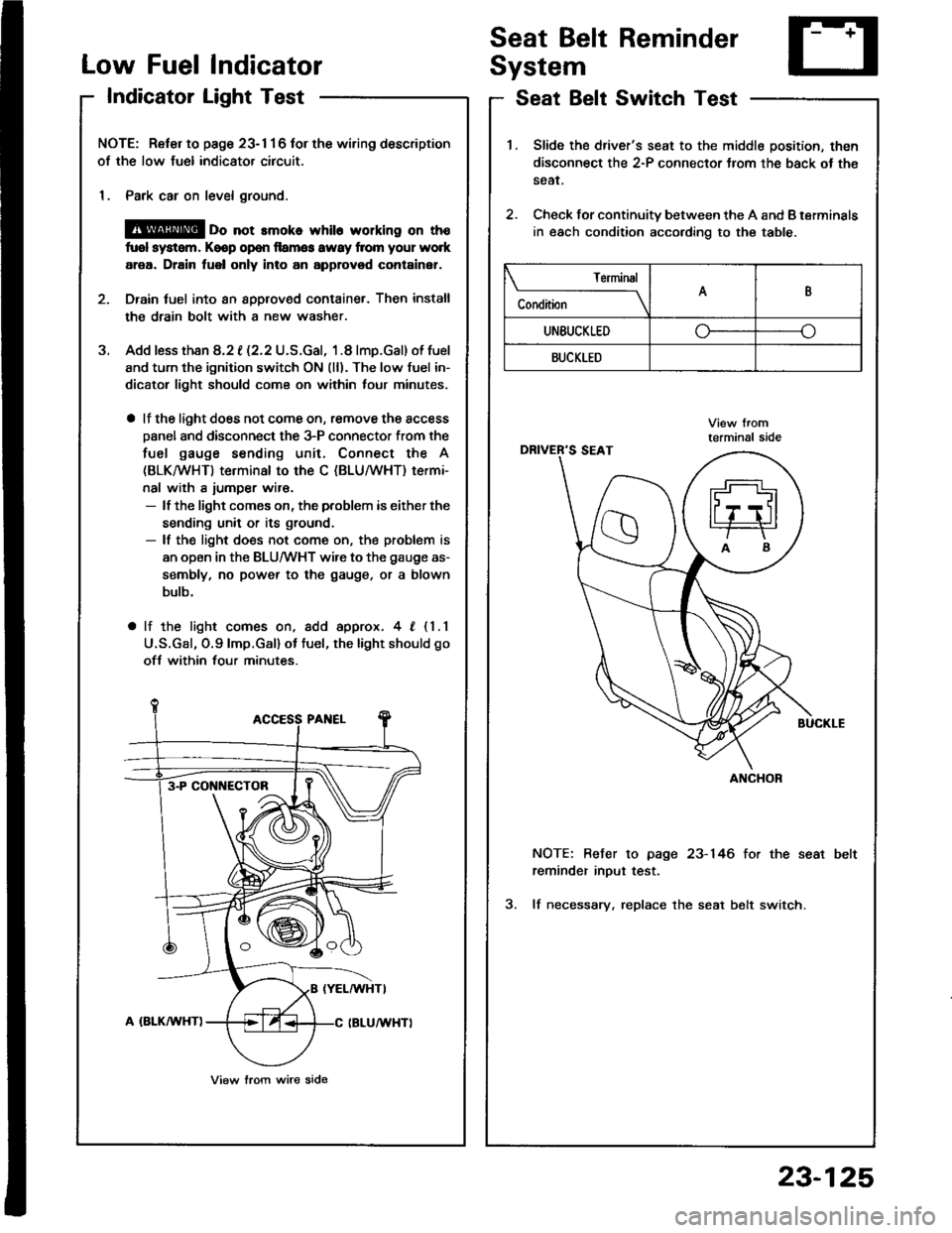
1. Park car on level ground.
@ oo not rmoko whil6 working on th€
fuol system, Keop op€n llamg3 awsy from your work
area. Drain fuel only into an approvod container,
Drain tuel into an 8pplov€d container. Then install
the drain bolt with a new washer.
Add less than 8.2 t (2.2 U.S.Gal, 1.8 lmp.Gal) of fuel
and turn the ignition switch ON (ll). The low fuel in-
dicator light should com€ on within lour minutes,
a lf the light does not come on, remove the access
Danel and disconnect the 3-P connector from the
fuel gauge sending unit, Connect the A
(BLKMHT) terminal to the C (BLU/WHT) termi-
nal with a iumper wir€.- lf the light comes on, the problem is either the
sending unit or its ground.- lf the light does not come on, the problem is
an open in the BLU/WHT wire to the gauge as-
sembly, no power to the gauge, or a blown
bulb.
a lf the light comes on, add approx. 4, {1.1
U.S.Gal, O.9lmp.Gal) ot tuel, the light should go
ofJ within four minutes.
3-P CONI{ECTOB
View lrom wire side
1.Slide the driver's seat to the middle position, then
disconnect the 2-P connector Jrom the back ot th€
sear.
Check for continuity between the A and B terminals
in each condition according to the table.
2.
NOTE: Befer to page 23-146 for the seat
reminder inout test.
3. lf necessary. replace the seat belt switch.
Terminal
C"** \AB
UNEUCKLEDo--o
BUCKLED
ANCHOR
23-125
Page:
< prev 1-8 9-16 17-24