Page 492 of 1413
Transmission
Removal {cont'd)
7. Remove the transmission housing mounting bolts.
Remove the drain plug and drain the automatic trans-
mission tluid (ATF). Reinstall the drain plug with anew sealing washer lsee page 14-93).
DRAIN PLUG18 x 1.5 mm49 N'm 15.0 kgt-m,36 tbt-fr)
9. Remove the splash shield.
6 x 10
CLIPS pcs.
10. Remove the cotter pins and castle nuts, then
separate the balljoints from the lower arm {see sec-
tion 18).
11. Remove the right dampe. fork bolt. then separate
right damper fork and damper.
PINCI{ BOLT
SELF.LOCKINGNUTReplace.COTTER PINReplace.
/\
14-100
DAMPER FORK
CASTLE NUT
Page 496 of 1413

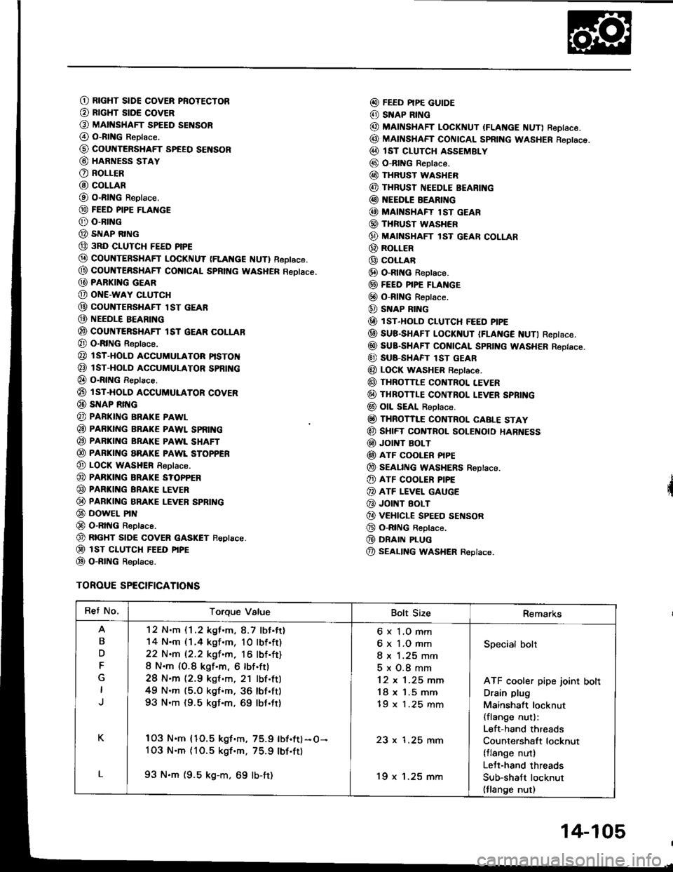
O RtcHT slDE covER pRoTEcToR
@ RrcHT stDE covER
O MAtt{sHAFr spEED sENsoR
@ o-RtNG Reptace.
@ cour{TERSHAFT SPEEO SENSOR
@ HARNESS STAY
O RoLLCR
@ COLLAR
O O-RING Reptace.
@ FEED PIPE FLAI{GE
@ o-RrNG
@ sIrlAP RING
@ 3RD CIUTCH FEED PIPE
@ COUNTERSHAFT LOCKNUT (FLAt{cE f{UTl Reptace.
@ coultTERsHAFf col{tCAL SpRtt{c WASHER Reotace.
@ PARKI G GEAR
@ oNE-waY cLUTcH
@ couNTERsHAFr lsr GEAR
@ NEEDLE BEARING
@ couNTERsHAFr tsr GEAR coLLAB
@ O-RING Reptace.
@ l sT-HoLD accuMuLAToR ptsToN
@ isT-HoLD ACCUMULAToR spBfi{c
@ o-RtNG Reptace.
@ rsT-HoLD ACGUMULAToR covER
@ SNAP Rrr{G
@ PAFKING BRAKE PAWL
@ PARKING BRAKE PAWL SPRII{G
@ PARKING BRAKE PAWL SHAFT
@ PARKING aRAKE PAWL SToPPER
@ LOCK wasHEn Reptace.
@ PARKI G BRAKE s?oPPER
@ PARKING BRAI(E LEVER
@ PARKI G BRAKE LEVER SPBING
@ DowEL PrN
@ O-RltIG Reptace.
@ RTGHT stoE covER GASKET Feptace.
@ isT ct-uTcH FEED ptpE
@ o-RtNG Reptace.
TOROUE SPECIFICATIONS
@ FEED PIPE GUIDE
@ SNAP RING
@ MAINSHAFT LocKNUT {FLANGE NUT) ReDIace.
@ MAfISHAFT CONTCAL SpRtNG WASHER Reotsce.
@ IsT cLUTcH ASSEMBLY
@ O-RING Reptace.
@ THRUST WASHER
@ THRUSI NEEDLE BEARI G
@ EEDLE BEARING
@ MAI'{SHAFT lsT GEAR
@ THRUST WASHER
@ MAINSHAFT lsT GEAR coLLAR
@ RoLLER
@ coLLAR
@ O-Rlt{c Reptace.
@ FEEo PIPE FLANGE
@ o-RING R€ptace.
@ SNAP RING
@ lsr-HoLD cLUTcH FEED ptpE
@ SUB-SHAFT LoCKNUT IFLAt{c€ NUTI Reptace.
@ suB-sHAFr cot{tcAl spRtNG WASHER Reptace.
@ SU8-SHAFT lST GEAR
@ LOCK WASHER f,eptace.
@ THRoTILE cor{TRoL LEVER
@ THRoTTLE coNTRoL I.EVER SPRING
@ oll sEAt Reptace.
@ THRoTTI"E coNTRoL CABLE STAY
@ sHtFT CONTROL SOLEI{O|O HARNESS
@ Jor T BoLT
@ ATF COOLER PIPE
@ SEAL|NG WASHERS Roptace.
@ ATF cooLER P|PE
@ ATF LEVEL GAUGE
@ JOINT EOLT
@ vEHtcLE spEED sEf{soR
@ o-RtNG Reptace.
@ DRAIN PLUG
@ SEALING WASHER Replace.
Ret No.Torque ValueBolt SizeRemarks
B
D
F
K
L
'12 N.m (1 .2 kgf .m, 8.7 lbJ.tt)
14 N.m (1.4 kgf.m, 10lbf.ft)
22 N.m 12.2 kgf.m, 16 lbf.ft)
8 N.m (O.8 kgf.m, 6 lbf.ftl
28 N'm (2.9 kgf .m, 21 lbf.ttl
49 N.m (5.O kgf.m, 36 lbf'ft)
93 N.m {9.5 kgf.m, 69 lbt.ft}
103 N.m {1O.5 kgf.m, 75.9 lbf.ftl-O-
1O3 N.m (10.5 kgf'm. 75.9 lbf.ft)
93 N.m (9.5 kg-m, 69 lb-ft)
6 x 1,O mm
6 x 1.O mm
I x 1.25 mm
5x0.8mm
12 x 1-25 mm
18 x '1.5 mm
tY x t.z5 mm
23 x 1.25 mm
'19 x 1.25 mm
Specialbolt
ATF cooler pipe joint bolt
Drain plug
Mainshaft locknut(flange nut):
Left-hand threads
Countershaft locknut(tlange nut)
Lett-hand threads
Sub-shatt locknut(flange nut)
14-105
Page 595 of 1413

Driveshafts
Inspection
Driveshaft Boot
Check the boots on the driveshaft for cracks,
leaking grease or loose boot bands.
lf any damage is found, replace the boot
Danos.
Looso Splines
Turn the driveshaft by hand and make sure the splines
and joint are not excessivelV loose.
lf damage is found, replace the inboard joint,
Twistod or Cracked
Make sure the driveshaft is not twisted or cracked.
Replace it if necessarv.
damage,
and boot
Removal
Loosen the wheel nuts slightly.
Raise the front of car and support it with safety
stands in the proper locataons (see section 1),
Remove the wheel nuts and front wheels,
Drain the transmission oil or fluid (see section 13 or
14).
NOTE: lt is not necessary to drain the differential oil
when the left driveshaft is removed.
Raise the locking tab on the spindle nut, then
remove the nut.
WHEEL NUT
6. Remove the self-locking nut and self-locking bolt.
GAUTION: Roplaco th€ s€lt.locking bolts if you can
sasily thread a non€elf-locking nut prst thoir nylon
locking inserts.(lf should require I N.m (0.1 kgt.m, 0.7 lbf.ft) ol
torqus to turn lhs nut on the bolt).
Remove the damDer fork.
SELF.LOCKING BOLT
10 x 1.25 mm
SELF-LOCKING NUT
12 x 1.25 mmReplace.(cont'dl
DBIVESTIAFT
EOOT BANDS
Replace.
16-3
Page 642 of 1413

OUTI.TT HOSE
Power Steering Pump
Removal
NOTE: Before disconnecting the hoses from the pump,
place a suitable containsr under the car.
1. Drain the power steering fluid from the rsservoir.
2. Remove the belt by loosening the pump adjusting
bolt and mounting bolts.
3. Disconnect the inlet and outlet hoses from the
pump and plug the hoses.
NOTE; Take care not to spill ths tluid on the body
or parts. Wipe off spillod fluid at once.
4. Remove the pump mounting bolt, then remove th€
pump
NOTE: Do not turn the steering whesl with the
pump removeo
5. Wrap the opening of th€ pump with a piece of taps
to provent any foreign mat€rial. Se6 pags 17-44 for
oumD instsllstion,
tNt.€T HOSE
Disassembly
Pulley Removal
1. Drain the fluid from the pump.
2, Hold the stee.ing pump in a vise with soft iaws, and
hold the pulley with the specialtool and remove the
pulley nut and pulley.
CAUTION: Bo clrstul not to damage the pump
ho$ing with thr iaw3 of ths vise.
NOTE: Pullev nut has left-hand threads.
PULLEY NUT {Left-hand thread)
(cont'dl
17-35
Page 652 of 1413

Steering Gearbox
Removal
NOTE: Using solvent and a brush, wash any oil and dirt
off the valve body unit, its lines, and the end if the gear-
box. Blow dry with compressed air.
1. Drain the power steering fluid as described on page
17 -21.
2. Rsise the front of car, and support on safety stands
in the propsr locations (see section 1).
3. Remove the front wheels.
il. Removs the st€ering joint cove.,
SIEERING JOIi{T COVEB
Remove the steering joint lower bolt, and move thejoint toward the column.
NOTE: Lock the steering shaft with the ignition key
to retain the steering shaft position.
Remove the cotter pin trom the castle nut and
removo the nut.
Installthe 10 mm hex nut on the balljoint.
Be sure that ths 10 mm hex nut is flush with the ball
ioint pin end, or the threaded section of the ball
ioint pin might be damaged by the ball iointremover.
NOTE: Remove the ball joint using the Ball Joint
Remover, 28 mm {07MAC - 5100200}. Refer to page
l8-11 fot how to use the ball joint rcmover,
Separat€ the tie-rod ball joint and knuckle using the
soscialtool.
CAUTION: Avold d.maging th. blllloint boot.
BALL JOlt{T REMOVER. 28 mm07MAC - SLqt2|X)
Disconnect the shift linkage {MfI model: see section
13, A/[ model see section 14).
Disconnect the heated oxygen sensor (H02S) con-
ngctor, and separate the three way catalytic conver-
ter by removing the s€lf-locking nuts.
NOTE: Always replace the gaskets with new ones.
OXycEt{S€NSOnOONNECTOR SELF.LOCKINGNUT
{cont'd)IHREE WAYCA?ALYTIC CONVERTEN
8.
10.
HEATED
Replacs.
17-45
Page 656 of 1413
Remove the cylinder pipe A and B from the gear-
box.
Drain the fluid from the cylinder fittings by moving
the steering rack back and forth,
Remove the two flange bolts, then remove the valve
body unit from the gearbox. {See page 17-51 for
valve body unit disassembly.)
FLANGE BOLT
CYLINDER PIPE B
VALVE BODY UNIT
11.Drill a 3 mm {0.12 in) diameter hole approximately
2.5 - 3.5 mm (0.10 - 0.14 in) in depth in the staked-
point on the cylinder.
NOTE: Do not allow metal shavings to enter the
cylinder housing.
STAKEO POINT
D.prh:2.5 - 3,0 mm 10.10 - 0.12 inl
CYUNDER END
12. Install a puller yoke to the stesring gearbox. Clamp
the puller yoke in a vise with soft iaws as shown,
then loosen and remove the cvlinder end.
PULLER YOKE:Commercirlly AvrilabloSn.p-Ono T/N qrie'-1
oTclo T/N 7372
(cont'd)
17-49
Page 947 of 1413

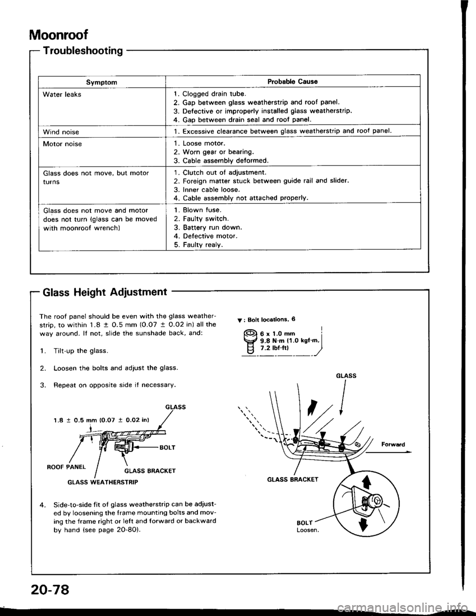
Moonroof
Troubleshooting
SymptomProbable Cause
Water leaks1
4
Clogged drain tube.
Gap between glass weatherstrip and roof panel.
Defective or improperly installed glass weatherstrip.
GaD between drain seal and roof panel.
Wind noise1. Excessive clearance between glass weatherstrip and roof panel.
Motor noise1. Loose motor.
2. Worn gear or bearing.
3. Cable assembly deformed.
Glass does not move, but motor
turns
1. Clutch out of adjustment.
2. Foreign matter stuck between guide rail and slider,
3. Inner cable loose.
4. Cable assembly not attached properly.
Glass does not move and motor
does not turn (glass can be moved
with moonroof wrench)
1. Blown fuse.
2. Faulty switch.
3. Battery run down.
4. Defective motor.
5. Faulty realy.
The roof panel should be even with the glass weather-
strip, to within l�8 t O.5 mm (O.O7 I 0.O2 in) all the
way around. It not, slide the sunshade back, and:
Y : Bolt locstions, 6
1.Tilt-up the glass.
Loosen the bolts and adjust the glass.
Repeat on opposite side it necessary.
2.
1.8 1 0.5 mm lO.O7 i0,O2 in)
i
ROOF PANELGLASS ERACKET
GLASS BRACKET
4.Side-to-side fit ot glass weatherstrip can be adjust-
ed by loosening the frame mounting bolts and mov-
ing the frame right or lelt and forward or backward
by hand (see page 2O-8O).
GLASS WEATI{ERSTRIP
f)
Glass Height Adiustment
20-78
Page 949 of 1413

Moonroof
Motor, Drain Tube and Frame Replacement
CAUTION: B€ caretul not to damag€ lhe seats, dash-
board and other interior trim.
1. Remove the glass (see page 2O-79) and headliner
(see page 20-98).
2. Disconnect the motor connector, and remove the
clips securing the ceiling light wire harness.
3. Remove the bolts and nuts, then remove the motor,
if necessarv,
NOTE: Make sure both sliders are parallel when in-
stalling the motor.
: 8olt, nut locationg
A
: Bolt, 2
6x1.Omm I9.8 N.m ILd tt.o kgf.-, I,.?- ", _,/
< : CliD locations. 2
CEILIING LIGHT
FRAME
B : Nut, 3
20-80
4.Disconnect the drain tubes.
Remove the bolts, then remove the trame from the
car.
NOTE: You may require assistance when removing
the frame.
: Eolt locations, I
6 x 1.0 mm
DRAIN TUBETo install, slide the draintube over the ftame nozzleat least 10 mm {O.4 in}.
6.
TUBE CI-IP
Pull the drain tubes out the front and rear pillars.
NOTE; Betore pulling out the drain tube, tie a string
to the end of it so it can be reinstalled.
Installation is the reverse ol the removal procedure.
NOTE:
a Clean the surtace of the frame.
a Check the trame seal.
a Check for water leaks.
7.
9.8 N.m (1.0 kgt m,7.2 rbr.ttl )
FRAME
FRONT