1994 HONDA INTEGRA battery harness
[x] Cancel search: battery harnessPage 1107 of 1413

Electrical
Special Tools
Troubleshooting
Tips and Precautions ................................ 23-3Five-stop Tloubleshooting ..............,...-..-... Z3-sSchematic Symbols ................................_. 23-6wire Color Cod€s ..................................... 23-6Relay and Control Unit Locations
Engine Compartment .........,............ ... --. 23-7Dsshboard and Door ..,,......................... 23-gDashboard and Floor ............................. 23-t OOuaner Panel .....-.....23-12Connector ldentification and WireHarness Routing ........ 23-i 3
Index to Circuits and Systems
Airbag ............... ...-..-... 2g-26sAir Conditioning ....,.. Section 2lAltelnator ......_.............. 23-99Anti-lock Brake Systsm (ABS) Section 19Automatic Transmission Section 14Battery .............. .......... 23-66Chafging System ........... 23-98rCigalstte Lighter .....................-...-......-..-.. Z3-2O4Cfock ................. ..........23-197rcruise Controf .......--..-... 23-242Distributor .................... 23-87Fan Controls ................. 23-1ogFuel and Emissions ... Section 1i*Fuses
Under-dash Fuse/Relay Box ................... 23-48Undor-hood ABS Fuse/Retay Box ............ 23-51Under-hood Fuse/Relay Box,.................. 23-52rGauges
Engine Coolant Temperature {ECT)Gauge ................ ..23-126Fuef cauge ............... 2g-123'Gauge Assembly ....--.23-113Speedometer .....-...,,. 23-114Tachometer .....,.....-.. 23-114Ground Distribution ........ 23-60Heater ,,,........,.... ..... Section 2lrHorn ................. ........... 23-199*fgnition Switch ............. 23-70fgnition Syst6m .......-..-.. 23-A7lgnition Timing .............. 23-89Indicator Lights"A/T Gear Position .............. ................... 23-1 32B1ak6 System ...,..,..-.23-127Engine Oil Pressura .............................. _ 23-1 51Low Fuel ............ ......23-125Malfunction Indicator Lamp {MlL} ...,,. Section I l
tfnteglated Control Unit ...29-144*lnterlock System ...................................... 23-1 3gLights, Exteriol
Back-up Lights ........... 23-179Brake Lights .............. 23-t8ltDaytime Running Lights {Csnada} ........... 23-156Front Palking Lights ............................. 23-1 65Flont Side Marker Lights ....................... 23-165Front Turn Signal Lights ........................ 23-1 65*Hazard Warning Lights .........................- 2g-1A4Headlights ................. 23-t6tLicense Plate Lights .............................. 23-1 69Taillights(Harchback) .......... 23-166
{Sedan) .............. .. 23-167Lights. Inteliol
Cargo Area Light {Hatchback) ...... -.. -.. -... 23-177Ceifing Light ........-..-.23-175
Dash Lights Blightness Controt .............. 23-t70Glove Box Lighr ................................... 23-1 69Spotfighr ............ ....-.23-174Trunk Light (Sedanl ............... .............. - 23.-177*Lighting Sysrem .......-.-... 23-152:Moonroof ,,.,.......,..,,,,,.-.23-211PGM-FI Systom ........ S€crion 11Power Distribution .,.-..--..23-54Power Door Locks .............,,..................... 23-233Power Mirors ..,..,....-...- 23-216Power Relays ...........,..... 23-68Power Windows ............ 29-222*Rear Window Defogger ........,... ..........,..... - 23-20,6Reminder Systems
Key-in Remindel System ....,.............,.... 23-1 50Lights-on Reminder System ................... 23-l 5f*Maintenance Reminder system ..,,.... -.. - -. 23-.1 2gSeat Belt Reminder System ..................- 23-125*Side Markel/Turn Signal/Hazard
Ffasher System .,..,..-.23.-1A4Spark Pfugs .........-...-..... 23-97Starting System ....,,.....-. 23-73*Stereo Sound System ...,.......................,,.. 23-l gg
Supplemental Restraint System {SRS} ......... 23-265Vehicfe Speed Sensor {VSS) .............--..-.... 23-122*Wiper/Washer Systom ...............--.........-..- Zg-254
rRead SRS pi€cautions on Page 23-271 betore workingin these areas.
-+
Page 1119 of 1413
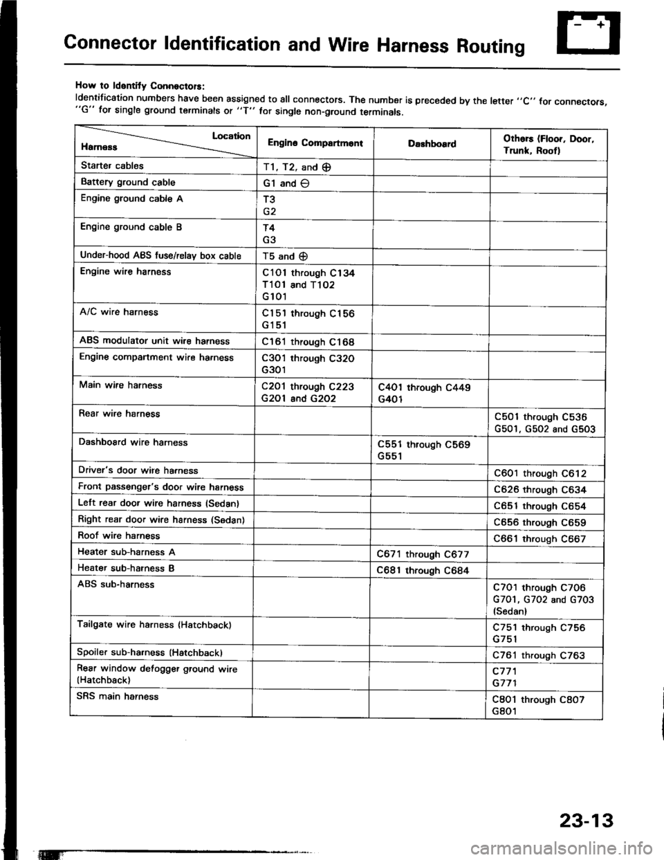
Connector ldentification and Wire Harness Routing
How to ldentity ConnoctolS:
ldentification numbers have been assigned to all connectors. The number is preceded by the letter ,,C,, for connecrors,"G" for single ground terminals ot "f" hr single non-ground terminals.
Location
HamessEngino CompartmontDarhboardOthors (Floor, Door,
Trunk, Rootl
Starter cablesT1, T2, and (E
Battery ground cableG1 and O
Engine ground cable AT3
Engine ground cable BT4
G3
Under-hood ABS fuse/relav box cableT5 and (D
Engine wire harnessC101 through C134
Tl Ol and T102
G 101
A/C wire harnessCl 5'l through C156
G151
ABS modulator unit wir€ harnessC161 through C168
Engine companment wire ha.nessC3O'l through C32O
G301
Main wire hatnessC2O1 through C223
G2Ol and G2O2
C4O1 through C449
G401
Rear wire harnessC501 through C536
G501, G502 and G5O3
DashboSrd wire harnessC551 through C569
G551
Driver's door wire harnessC601 through C612
Front passenger's door wire harnessC626 through C634
Left rear door wire harness (Sedan)C651 through C654
Right rear door wire harness (Sedan)C656 through C659
Roof wire harnessC661 through C667
Heater sub-harness AC671 through C677
Heater sub-hatness BC681 through C684
ABS sub-harnessC7O1 through C7O6
G7O1, G702 and G703(Sedan)
Tailgate wire harness (Hatchback)C751 through C756
Spoiler sub-ha.ness (Hatchback)C761 through C763
Rear window defogger ground wire(Hatchback)c77'l
G771
SRS main harnessC8O1 through C8O7
G801
23-13
Page 1120 of 1413
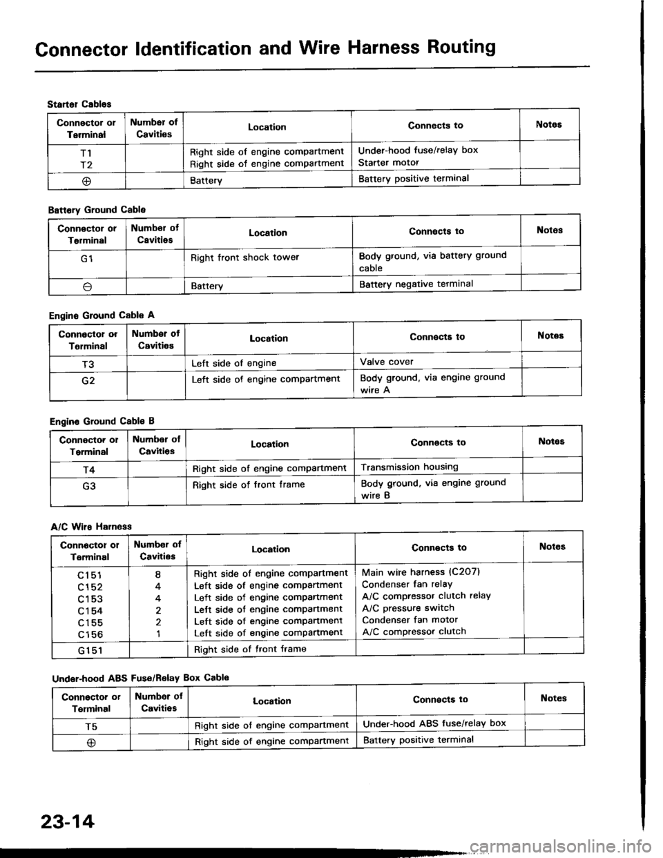
Gonnector ldentification and Wire Harness Routing
Startol cablos
Connector or
Terminal
Numbsr of
CavitiesLocationConnects toNotos
T1
r2
Right side of engine compartment
Right side of engine compartment
Under-hood fuse/relay box
Starter motor
@BatteryBattery positive terminal
B8ttory Ground Cable
Engine Ground Cable A
Engine Ground Cable B
A/C Wiro H81n6ss
Under-hood ABS Fus€/Relav Box Cablo
Conn€ctor or
T€rminal
Numbor of
CsvitiesLocationConnects toNotos
G1Right front shock towerBody ground, via battery ground
cable
\lBatteryBattery negative tetminal
Connoctor or
Tolminal
Number of
CavitiesLocationConnocta toNotes
T3Left side of engineValve cover
G2Left side of engine compartmentBody ground. via engine ground
wire A
Connoctor or
Torminal
Number ol
CavitiosLocationConnocts toNot€s
r4Right side of engine compartmentTransmission housing
G3Right side of front frameBody ground, via engine ground
wire B
Connoctor 01
Terminal
Numbor of
CavitiesLocationConnects toNotes
cl51
cl52
c153
c1 54
c155
c156
I
4
4
1
Right side ol engine comPartment
Left side of engine compartment
Left side of engine comPartment
Lett side ot engine compartment
Left side of engine comPanment
Left side of engine compartment
Main wire harness (C2O7)
Condenser fan relay
A/C compressor clutch relay
A/C pressure switch
Condenser fan motor
A/C compressor clutch
G151Right side of tront Jrame
Conngctor or
Terminal
Numbor ot
Caviti€sLocalionConnects loNotes
T5Right side of engine comPartmentUnder-hood ABS fuse/relay box
@Right side of engine compartmentBattery positive terminal
23-14
Page 1177 of 1413
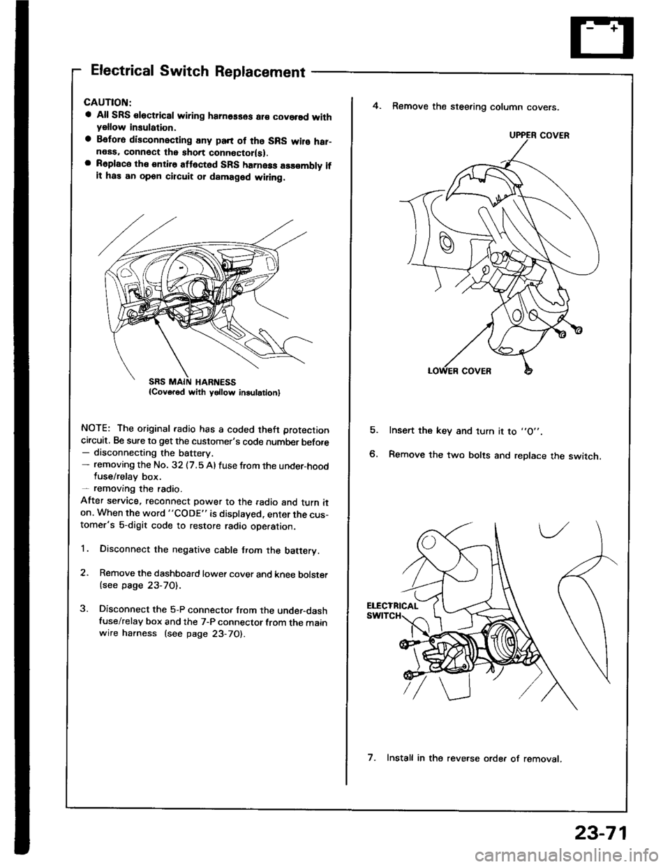
Electrical Switch Replacement
a All SRS €lectric8l wiring hamosses ar€ covorsd withyellow insulation,
a Befora disconnecting any pan of tho SRS wilo har-neas. connect the short connoctor(sl.a R6place the entire attect6d SFS harness assombly ifit has an opon circuit 01 damaged wiling.
NOTE: The original radio has a coded theft protection
circuit, Be sure to get the customer's code number before- disconnecting the battery.- removing the No. 32 (7.5 Al fuse from the under-hoodluse/relay box.- removang the radio.
After service, reconnect power to the radio and turn iton. When the word "CODE" is displayed, enter the cus-tomer's 5-digit code to restore radio ope.ation.
1. Disconnect the negative cable from the batery.
2. Remove the dashboard lower cover and knee bolster
{see page 23-70).
3. Disconnect the 5-P connector from the under-dashfuse/relay box and the 7-P connector from the mainwire harness (see page 23-70).
E
4. Remove the steering column covers.
Insert the key and turn it to ,,O',.
Remove the two bolts and replace the switch.
UPPER COVER
7. Install in the reve.se orde. of removat.
23-71
Page 1178 of 1413
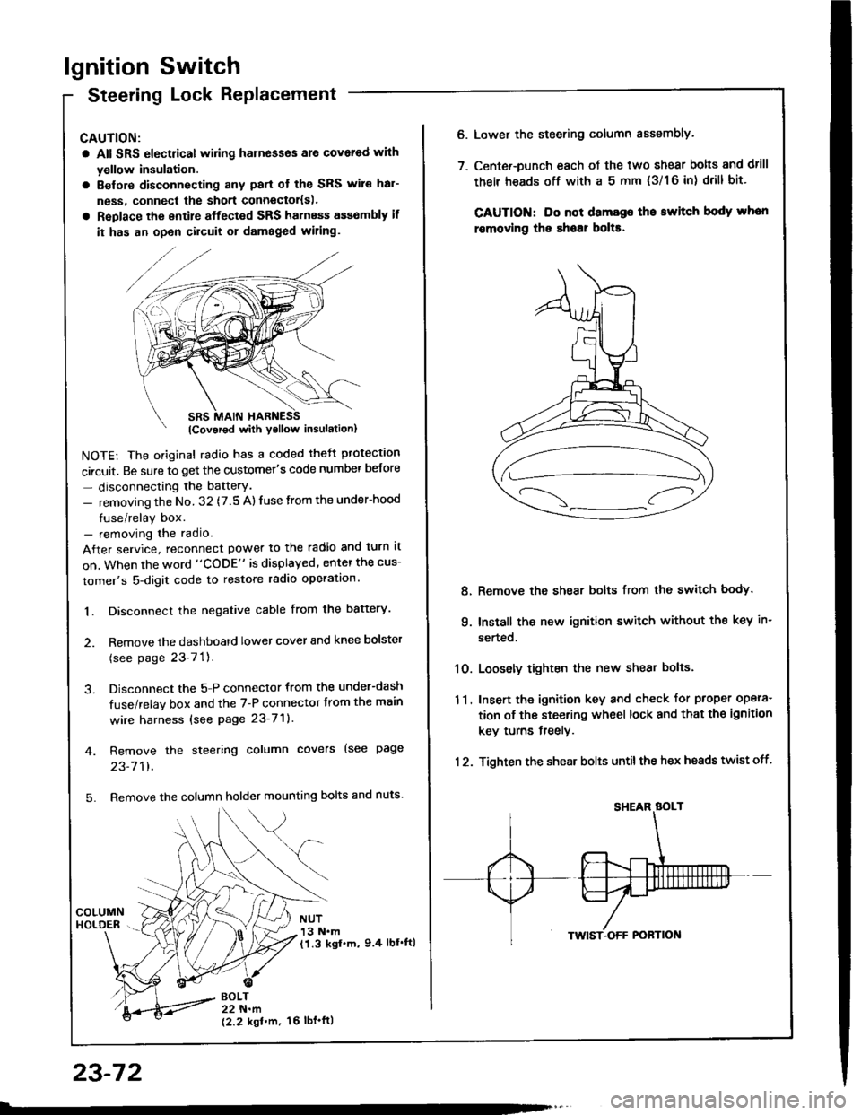
lgnition Switch
Steering Lock Replacement
CAUTION:
a All SRS electrical wiring harnesses ale covsred with
yellow insulation.
a Belore disconnecting any parl ot the SRS wir€ hal-
ness, connecl the short connector{s).
a Replace the entire alfected SRS harness a$6mbly il
it has an open circuit or damaged wiring.
NOTE: The original radio has a coded thett protection
circuit. Be sure to get the customer's code number betore
- disconnecting the batterY.
- removing the No. 32 (7.5 A) fuse from the under-hood
fuse/relay box.- removing the radio.
After service, reconnect power to the radio and turn it
on. When the word "CODE" is displayed, enter the cus-
tomer's 5-digit code to restore radio operation.
1. Disconnect the negative cable from the battery.
2. Remove the dashboald lower cover and knee bolster
(see page 23-7'l ).
3. Disconnect the 5-P connector from the under-dash
fuse/relay box and the 7-P connector trom the main
wire harness {see page 23-71).
4. Remove the steering column covers (see page
23-711.
5. Remove the column holder mounting bolts and nuts'
BOLT22 N.m
12.2 kgl'm.
NUT13 N.m(1.3 kgf.m, 9.4 lbl'ftl
23-72
16 tbt.ftl
6. Lower the steering column sssembly.
7. Center-Dunch each oJ the two shear bolts and drill
their heads off with a 5 mm {3/1 6 in) drill bit'
CAUTION: Do not dama96 tho switch body whon
r€movlng the shoar bol$.
Remove the shear bolts from the switch body.
Install the new ignition switch without the key in-
serted.
Loosely tighten the new shear bolts.
Insert the ignition key and check for proper opera-
tion of the steering wheel lock and that th€ ignition
key turns freely.
Tighten the shear bolts untilthe hex heads twist off.
8.
q
10.
11.
12.
Page 1186 of 1413
![HONDA INTEGRA 1994 4.G Workshop Manual Starting
Startel
System
Overhaul
from clutch side.
-s@]
MOLYBDENUMDISULFIDE
CAUTION: Disconnecl th€ battery n€gative cable befole
lomoving the startet.
NOTE: The original radio has a coded theft p HONDA INTEGRA 1994 4.G Workshop Manual Starting
Startel
System
Overhaul
from clutch side.
-s@]
MOLYBDENUMDISULFIDE
CAUTION: Disconnecl th€ battery n€gative cable befole
lomoving the startet.
NOTE: The original radio has a coded theft p](/manual-img/13/6067/w960_6067-1185.png)
Starting
Startel
System
Overhaul
from clutch side.
-s@]
MOLYBDENUMDISULFIDE
CAUTION: Disconnecl th€ battery n€gative cable befole
lomoving the startet.
NOTE: The original radio has a coded theft protection
citcuit. Be sure to get the customer's code number before
- disconnecting the batterY.- removing the No.3 2 (7.5 A) fuse from the under-hood
fuse/relay box.- removing the tadio.
Atter service, reconnect power to the radio and turn at
on. When the word "CODE" is displayed, enter the cus-
tomer's 5-digit code to restore radio operation.
tr./.' BRUSH HOLDERTest, page 23-8'l
ERUSH
COVER
I
6
OVERRUNNING CLUTCH ASSEMBLYInspection, page 23_84
SOLENOIDPLUNGERInspection, page 23-85
BRUSH HOLOER
ARMATURE
STARTERSOLENOIDTest, page 23-78
PINION GEAR IDLER GEAR
Inspection, page 23-11
IDLER GEAR
I
@*
SOLENOID HOUSING
HARNESS BRACKET
STEEL BALL
install steel ball
lnspection and Test,page 23-82
ROLLER BEARINGSand CAGEPrevenl rollers trom being scattered and lost.
MOLYBDENUM DISULFIDE
_R1
MOLYADENUMDISULFIDE
23-80
ENO COVER
ARMATURE
GEAR HOUSING
Page 1226 of 1413
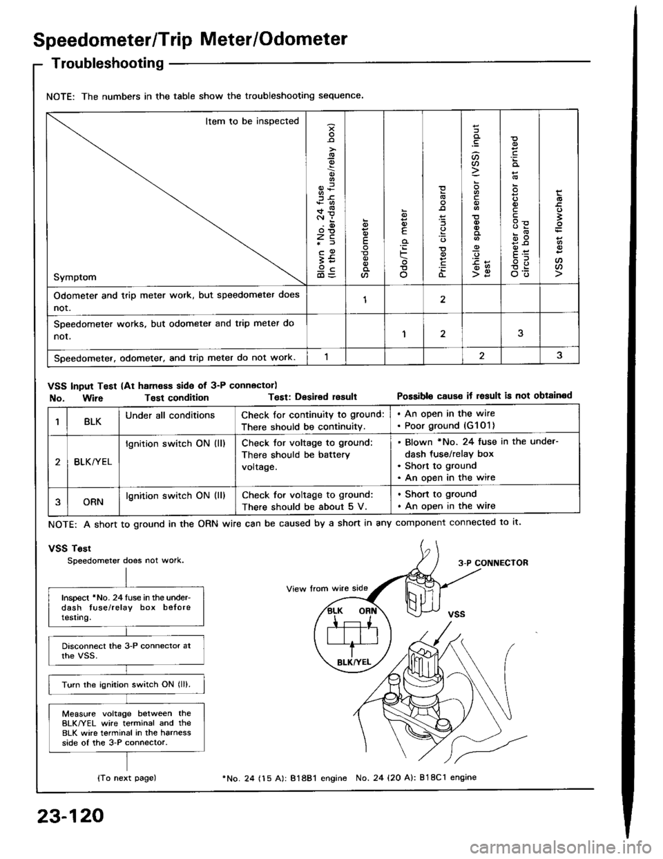
Speedometer/Trip Meter/Odometer
Troubleshooting
NOTE: The numbers in the table show the troubleshooting sequence.
Item to be inspected
Symptom
-9
;6+*c.r i.(D
zc*f
;59cd)=
E
a
6
E
'iF
o
(L
:lt)a
o
-9
>g
q)
qlv
E
'
E
oo
Odometer and trip meter wotk, but speedometer does
not.12
SDeedometer works, but odometer and trip meter do
nor,1
Speedometer. odometer, and trip meter do not work.
VSS Input Test (At ham€ss side of 3-P connector)
No. Wir6Tost conditionT€st: Desirsd resultPossible cause it result is not obtained
1BLKUnder all conditionsCheck for continuity to ground:
There should be continuity.
. An open in the wire. Poor ground (G1O1)
BLK/YEL
lgnition switch ON (ll)Check tor voltage to ground:
There should be battery
voltage.
Blown *No. 24 fuse in the unde.-
dash tus€/relay box
Short to ground
An open in the wire
ORNlgnition switch ON (ll)Check for voltage to ground:
There should be about 5 V.
. Shon to ground
. An open in the wire
NOTE: A short to ground in the
vSS Tost
Speedometer does not work.
ORN wire can be caused by a short in any component connected to lt.
3-P CONNECTOR
Inspect 'No. 24luse in the under-dash tuse/relay box beloretesting.
Turn the ignition switch ON lll).
Measure voltage between theBLK/YEL wire terminal and the8LK wire terminal in the harnessside of the 3-P connector.
{To next page)
23-120
24 (15 A): 81881 engine No. 24 {20 A): 818C1 engine
Page 1249 of 1413
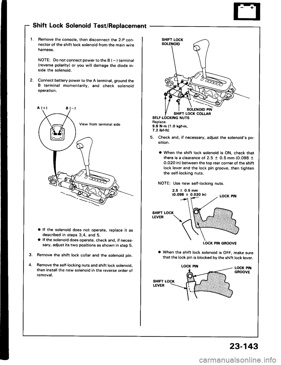
Shift Lock Solenoid Test/Replacement
Remove the console, then disconnect the 2-p con-neclor oJ the shift lock solenoid from the main wireharness.
NOTE: Do not connect powe. to the B { - ) terminat(reverse polarity) or you will damsge the diode in-side the solenoid.
Connect battery power to the A terminal, ground theB terminal momentarily. and check solenoidoDeralron.
a lf the solenoid does not operate, replace it asdescribed in steps 3,4, and 5.a lJ the solenoid does operate, check and, if neces-sary, adiust its two positions as shown in step 5.
Remove the shift lock collar and the solenoid pin.
Remove the selflocking nuts and shift lock solenoid,then installthe new solenoid in the reverse otder otremovat.
a
Replace.9,8 N.m {1.0 kgl.m,7.2 tbl.hl
5. Check and, if necessary, adjust the solenoid's po-
sition.
a When the shift lock solenoid is ON, check that
there is a clearance ol 2.5 1 O.5 mm {O.O98 I
O.O2O in) between the toD rear corner ot the shift
lock lever 8nd the lock pin groove, then tighten
the selflocking nuts.
NOTE: Use new self-locking nuts.
2.5 t O.5 mm{0.098 t 0.020 inl
SHIFTLEVEB
LOCK PIN GROOVE
a When the shift lock solenoid is OFF, make surethat the lock pin is blocked bv the shift lock lever.
LOCK PINGROOVE
LOCK
LOCK PIN
23-143