Page 1186 of 1413
![HONDA INTEGRA 1994 4.G Workshop Manual Starting
Startel
System
Overhaul
from clutch side.
-s@]
MOLYBDENUMDISULFIDE
CAUTION: Disconnecl th€ battery n€gative cable befole
lomoving the startet.
NOTE: The original radio has a coded theft p HONDA INTEGRA 1994 4.G Workshop Manual Starting
Startel
System
Overhaul
from clutch side.
-s@]
MOLYBDENUMDISULFIDE
CAUTION: Disconnecl th€ battery n€gative cable befole
lomoving the startet.
NOTE: The original radio has a coded theft p](/manual-img/13/6067/w960_6067-1185.png)
Starting
Startel
System
Overhaul
from clutch side.
-s@]
MOLYBDENUMDISULFIDE
CAUTION: Disconnecl th€ battery n€gative cable befole
lomoving the startet.
NOTE: The original radio has a coded theft protection
citcuit. Be sure to get the customer's code number before
- disconnecting the batterY.- removing the No.3 2 (7.5 A) fuse from the under-hood
fuse/relay box.- removing the tadio.
Atter service, reconnect power to the radio and turn at
on. When the word "CODE" is displayed, enter the cus-
tomer's 5-digit code to restore radio operation.
tr./.' BRUSH HOLDERTest, page 23-8'l
ERUSH
COVER
I
6
OVERRUNNING CLUTCH ASSEMBLYInspection, page 23_84
SOLENOIDPLUNGERInspection, page 23-85
BRUSH HOLOER
ARMATURE
STARTERSOLENOIDTest, page 23-78
PINION GEAR IDLER GEAR
Inspection, page 23-11
IDLER GEAR
I
@*
SOLENOID HOUSING
HARNESS BRACKET
STEEL BALL
install steel ball
lnspection and Test,page 23-82
ROLLER BEARINGSand CAGEPrevenl rollers trom being scattered and lost.
MOLYBDENUM DISULFIDE
_R1
MOLYADENUMDISULFIDE
23-80
ENO COVER
ARMATURE
GEAR HOUSING
Page 1256 of 1413

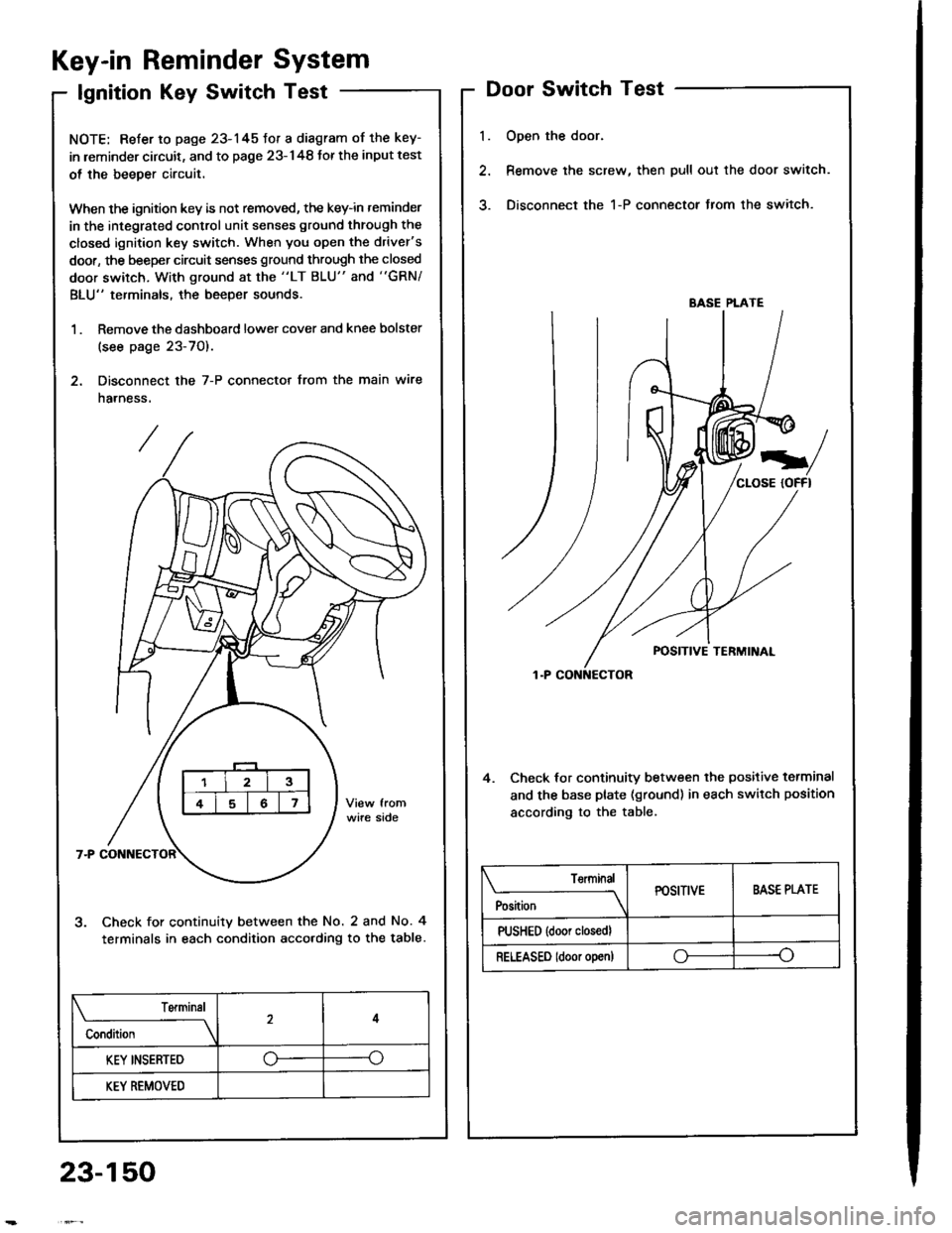
Key-in Reminder System
lgnition Key Switch Test
NOTE: Refer to page 23-145fot a diagram of the key-
in leminder circuit, and to page 23-148 Jor the input test
ol the beeper circuit.
When the ignition key is not removed, the key-in reminder
in the integrated control unit senses ground through the
closed ignition key switch. When you open the driver's
door, the beeper circuit senses ground through the closed
door switch, With ground at the "LT BLU" and "GRN/
BLU" terminals, the beeper sounds.
1 . Remove the dashboard lower cover and knee bolster
(see page 23-70).
2. Disconnect the 7-P connector from the main wire
harness.
Check for continuity between the No. 2 and No. 4
terminals in each condition acco.ding to the table.
l.
Door Switch Test
Open the door.
Remove the screw, then pull out the door switch.
Disconnect the 1-P connector from the switch.
4. Check lor continuity between the positive terminal
and the base plate (ground) in each switch position
according to the table.
BASE PLATE
Position
TerminalPOSITIVEBASE PLATE
PUSHED {door closedl
RELEASED ldoor o!en)oo
Terminal
Condition
4
KEY INSERTED--o
KEY REMOVED
23-150
Page 1257 of 1413

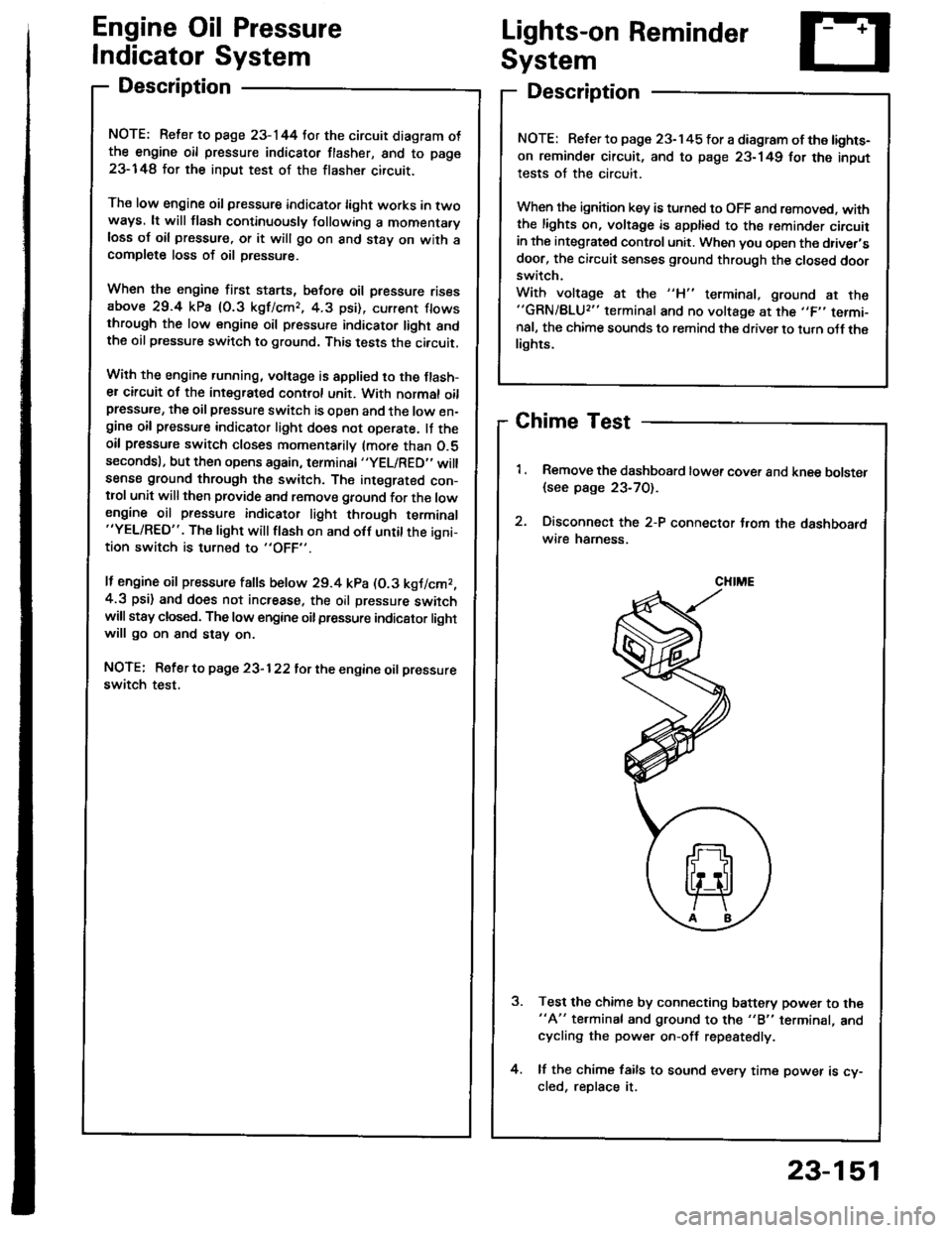
Engine Oil Pressure
Indicator System
Description
NOTE: Reter to page 23-144 tor the circuit diagram otthe engine oil pressure indicator flasher, snd to page
23-148 lor the input test of the flasher circuit.
The low engine oil pressure indicator tight works in twoways. lt will flash continuously following a momentaryloss of oil pressure, or it will go on and stay on with acomplete loss of oil pressure.
When the engine first starts, before oil Dressure risesabove 29.4 kP8 10.3 kgf/cmr, 4.3 psi), current flowsthrough the low engine oil pressure indicator light andthe oil pressure switch to ground. This tests the circuit.
Wilh the engine running, voltage is applied ro the ftash-er circuit of the integrated control unit. With normal oilpressure, the oil pressure switch is open and the low en-gine oil pressure indicator light does not operate. lf theoil pressure switch closes momentarily (more than O.5secondsl, but then opens again, terminal "yEL/RED,'will
sense ground through the switch. The integrated con-trol unit willthen provide and remove ground for th€ lowengine oil pressure indicator light through terminal"YEL/RED". The light will flash on and olf until the igni-tion switch is turned to "OFF".
lf engine oil pressure falls below 29.4 kPa (O.3 kgJ/cmr,4.3 psi) and does not increase, the oil pressure switchwillstsy closed. The low engine oilpressure indicator lightwill go on and stav on.
NOTE; Refer to page 23-122lot the engine oil pressure
switch test.
Lights-on Reminder
System
Description
Chime Test
Remove the dashboard lower cover and knee bolster
{see page 23-70).
Disconnect the 2-P connector t.om the dashboardwire hamess.
Test the chime by connecting battery power to the"A" te.minal and ground to the "B" terminal, andcycling the power on-off repestedly.
lf the chime fails to sound every time power is cy-cled, reDlace it.
NOTE: Refer to page 23-145 tor a diagram of the lights-
on reminder circuit, and to page 23-149 for the input
tests of the circuit.
When the ignition key is turned to OFF 8nd removed. withthe lights on, voltage is apptied to the reminder circuitin the integrat€d control unit. When you open the driver,sdoor, the circuit senses ground through the closed doorswitch.
With voltage at the "H" terminal, ground at the"GRN/BLU2" terminal and no voltage at the ,,F,' termi-nal, the chime sounds to remind the driver to turn oJf thelights.
CHIME
23-151
Page 1264 of 1413
Lighting System
Combination Light/Turn Signal Switch Test
CAUTION:
a Atl SRS Oloctricsl wiring harnesses ar6 covered with
yellow insulation.
a Bslor€ disconnecting any pan ot the SRS wire har-
ness, connact the short connsctollsl.
a Replace the sntire aftectad SRS harne$ assembly if
it has an opon circuit or damagod wiring.
1. Remove the dashboard lower cover and steering
column covers (see page 23-71).
2. Disconnect the 4-P and 7-P connectors from the
switch.
3. Check the connector and socket tetminals to be sure
they are all making good contact. lf the terminals are
bent, loose, or cotroded, repair them as necessary,
and recheck the system.
4. Check tor continuitv between the terminals in each
switch position according to the table.
SRS MAIN HAR ESS
B
D
G
H
4-P CONI{ECTOR
7.P CONNECTOR
23-158
Page 1307 of 1413

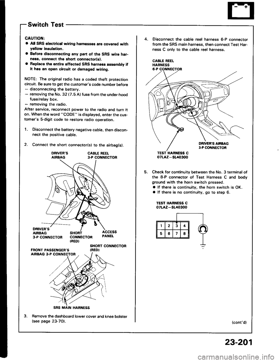
Switch Test
CAUTION:
a All SRS el6ctrical wiring harnossos are covarod withyellow inaulation.
a Beforo disconnecting any pan ot the SRS wire har-neaa, connoct ths short connector(s).a Roplace the entil€ afloctod SRS harne$ a$6mbly ifit has an open circuit or dsmagad wlring.
NOTE; The original radio has a coded theft protection
circuit. Be sure to get the customer's code number before- disconnecting the battery.- removing the No. 32 {7.5 A) fuse lrom the under-hoodtuse/relav box.- removing the radio.
After service, reconnect power to the radio and turn iton. When the word "CODE" is displayed, enter the cus-tomer's 5-digit code to restore radio operation.
1. Disconnect the battery negative cable, then discon-nect the positive cable.
2. Connect the short connector(sl to the airbag(sl.
DRIVER'SAIRBAGCABLE REEL3.P CO NECTOR
DRIVER'SAIRBAG3-PCO'TNECTOR COI{NECTOR{RED}
ACCESSPAI{EL
SHORT CONTIECTOR{REO}
Remove the dashboatd lower cover and kne€(see page 23-701.
5.
4. Disconnect the cable reel harness 6-P connector
from the SRS main harness, then connect Test Har-
ness C onlv to the cable reel harness.
CABLE REELHARNESS
TEST HAR ESS CoTLAz - SL/l{,3OO
Check for continuity between the No, 3 terminal ot
the 8-P connector of Test Harness C and body
ground with the horn switch pressed.
a lf there is continuity, the horn switch is OK.a lf there is no continuity, go to step 6.
TEST HARNESS COTLAZ-SI/I()3OO
(cont'd)
bolster
23-201
Page 1352 of 1413
Cruise Control
Control Unit Input Test
CAUTION:
a All SRS olectrical wi ng harnessos are covored with
yellow insulation.
a Botore disconnecting any part of th6 SRS wire har-
neaa, connect the short connoctor(sl.
a Roplace the €ntir€ affectod SRS hamass assembly il
il has an opan circuit or damaged wifng.
1 , Remove the dashboard lower cover and knee bolster(see page 23-70).
2. Disconnect the 14-P connector trom the control unit.
Insoect the connector and socket terminals to be
sure they are all making good contact.
a lf the terminals are bent, loose or corroded, repair
them as necessary, and recheck the system.
a It the terminals look OK, make the following in-
Dut tests at the connector.- It any test indicates a problem, find and cor-
rect the cause. then recheck the svstem.- lf allthe input tesls prove OK, the control unit
must be faulty; replace it.
CRUISE CONTROL UNIT
14-P COI{NECTOR
SRS MAIN HARNESS
23-246
Viow from wire side
Page 1354 of 1413

Cruise Gontrol
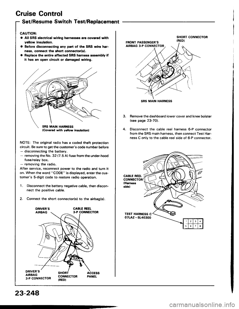
Set/Resume Switch Test/Replacement
CAUTION:
a All SRS ol6ct cal widng herne$a3 err covorod with
y6llow insulation.
a Bototo disconnecting any part ot tho SRS wiro h8r-
n6sa, connoct tho ghort connector(sl,
a Rsplaco the antire aftected SRS harness arsombly if
it has an op6n chcuit or damagod wiring.
NOTE: The original radio has a coded theft protection
circuit, Be sure to get the customer's code number befor€- disconnecting the battery.- removing the No. 32 (7.5 A) fuse from the under-hood
fuse/relay box.- removing the radio.
Afte, service, reconnect power to the radio and turn it
on. When the word "CODE" is displayed, enter the cus-
tomer's s-digit code to restore radio op€ration.
1 . Disconnect the battery negative cable, then discon-
nect the Dositive cable.
2. Connect the short connector(s) to the airbag(s).
DRIVER'SAIRBAG3-P CONNECTOR
SHORT ACCESSCON]TECTON PANEL(REDI
23-248
SRS MAIN HARNESS
3. Remove the dashboard lower cover and knee bolster(see page 23-70).
4. Oisconnect the cable reel harness 6-P connector
from the SRS main harness, then connect Test Har-
ness C onlv to the cable reel side of 6-P connector.
CABLE REELCONNECTORlHlrnoa!Eidol
Page:
< prev 1-8 9-16 17-24