Page 1025 of 1413
Hatch Latch and Lock CYlindet
Replacement
NOTE: Take care not 10 bend the cylinder rod and hatch
opener cable.
1. Remove the rear trim panel (see page 20-921.
2. Disconnect the cylinder rod and connector.
3. Remove the hatch latch.
>: Screw locatiois, 3
^ 6x1.omm I
{Dm s.e N m (1.0 ksl m,- ,?tb:tn __/
20-156
4. Disconnect the hatch opener cable.
HATCH LATCH
5. Remove the lock cylinder by turning it 45o
>: Bolt localion, 1
o.
CYLINDER ROD
lnstallalion is the reverse of the removal procedure.
NOTE:
a Apply grease to the hatch latch.
HATCH LATCH
Make sure the hatch locks securely.
Make sure the hatch opens properly.
Make sure the connector is connected properly.
a
a
a
Page 1026 of 1413
Trunk Lid Latch and Lock Cylinder
Replacement
NOTE: Take care not to bend the cylinder rod and trunklid opener cable.
l. Disconnect the connector and trunk lid opener cable.
CONNECTOR
2. Disconnect the cylinder rod.
CYLINDERROD
Remove the bolts, then remove the trunk lid latch.
A : Bolt locations, 3
LIDCABLE
4. Remove the lock cylinder cover.
HOOKS
LOCK CYLINDERCOVER
5. Remove the bolt, then pull the lock cylinder out. Re,move the lock cylinder trom the cylinder rod, thentake them out.
: Bolt location, 'l
CLIP
CLIPS
F 6xl.Omm I
q;i!!"jy
LOCKCYLINDER
CYLINDER ROD
6. Installation is the reverse ol the removat proceoure.
NOTE:
a Apply grease to the trunk lid latch,
a Make sure the trunk lid locks securelV.a Make sure the trunk lid opens properly.a Make sure the connector is connected properly.
/ ./,.,
,/'e4
20-157
Page 1028 of 1413
Hatch Spoiler
Replacement
a Take care not to scratch the hatch.a Open the hatch.
1. Remove the hatch side trim and hatch trim panel (seepage 2O-146).
2. Remove the nuts and disconnect the connector.
: Nut locations, 4
6 x 1.0 mm
Ch 9.8 N.m(J (1.0 ksl m, I__. 7,4b1!t ,/coI{t{EcroR
Remove the hatch spoiler by turning the clip nut onthe left side counterclockwise.
HATCH SPOILER
3. Installation is the reverse of the removal procedure.
Fender Well Trim and
Wheelhouse Protector
Replacement
a Take care not to bend the tender well trim.a Before installing the lender well trim, clean the bodvbonding surface with a sponge dampened in alcohol.a After cleaning, keep oil, g.ease or wafer lrom getlingon the surface.
> i Scr€w locations.
I
ADHESIVEFENDER WELLTRIM
20-159
Page 1039 of 1413

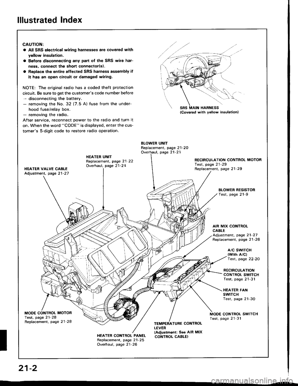
lllustrated Index
CAUTION:
a All SRS electrical wiling harnesses are covered with
y€llow insulation.
a Bafore disconnecting any pan of the SRS wile har-
ness. connect the sholt connectorlsl.
a Replace the sntire aflected SRS halness assembly if
it has an open circuit or damaged wiring.
NOTE: The original radio has a coded thelt protection
circuit. Be sure to get the customer's code number before- disconnecting the battery.- removing the No. 32 (7.5 Al fuse lrom the under-
hood fuse/relav box.- removing the radio.
After service, reconnect power to the radio and turn it
on. when the word "CODE" is displayed, enter the cus-
tomer's 5-digit code to restore radio operation.
BLOWER UNITReplacement, page 21-2OOverhaul, page 21-21HEATER UNITRepfacement, page 2l 22Overhaul, page 21-24
RECIRCULATION CONTROL MOTORTest, page 21-29Replacement, page 21 29I{EATER VAIVE CABLEAdjustment, page 21-27
BLOWEN RESISTORTest, page 21-9
AIR MIX CONTROLCABLEAd,ustment, page 21-27Replacement. page 21-26
a/c swrTcH(wirh A/clTest, page 22-20
RECIRCULATIONCONTROL SWITCHTest, page 21-31
HEATER FANswtTcHTest, page 2'l-3O
MODE CONTROL MOTORTest, page 21-28Repfacement, page 21'28
MODE CONTROL SWITCHTest, page 21'31
HEATER CONTROL PANELRepf acement, page 21 -25
Overhaul, page 21-26
TEMPERATURE CONTROLLEVER(Adjustmonl: See AIR MIXCONTROL CABLE}
SRS MAIN HARNESS
W,
21-2
I
Page 1047 of 1413
Does the blower motor run atprogressively higher speeds?Raplaca tho hollar fan rwitch.
Ropair opon or cau36 ol oxcoalivtrosbtanco in tho appaopaiatowire(3| b6twoon thg hostct lanswitch and tho blower todstor.
Turn the ignition switch OFF.
Remove the heater control panel(see page 21-25).
Check each wire for continuity be-tween the heater tan switch 6Pconnector and body ground.. BLU wire. BLUMHT wire. BLU/YEL wke. BLU/BLK wire
Raplaca tha haater lan awltch.
Bopair shon in the wir6{s} b€-lwo€n lho heatot lan switch rndth6 blowor ro3bto?.
From page 21-9
From page 21-9
View trom whe side
ilil
!\i
-l
I
View from wire side
BLU/U,HT
Troubleshooting
Blower Motor Speed (cont'd)
21-10
--
Page 1048 of 1413
Blower Motor
View from wire side
View from wire side
Blowor motor doos noi iun at all.
check the No. 37 (4o A) fuse intho under-hood fuse/relay box.
At th€ blower motor 2P connec-tor, connect the BLU/8LK wirc ter-minal to body ground wath ajumpe. wire.
Turn the ignition switch ON (ll).
Does the blower motor run?
Disconnect the blower motor 2Pconnector, and measure the vol-tago between the ELU/wHT wireterminal {+} and body ground
{-}.
Turn the ignition switch OFF.
Remove the blower motor relavfrom the under-hood fuse/relavbox and test it {see page 21-3O}.
Roplaco tho blowor motor rolay.
Measure the voltage betwgen theNo. 1 terminal (+) and bodyground (- ).
To page 21-12
To page 2l-13
"uf"'\'
,)
(cont'dl
21-11
Page 1051 of 1413
Troubleshooting
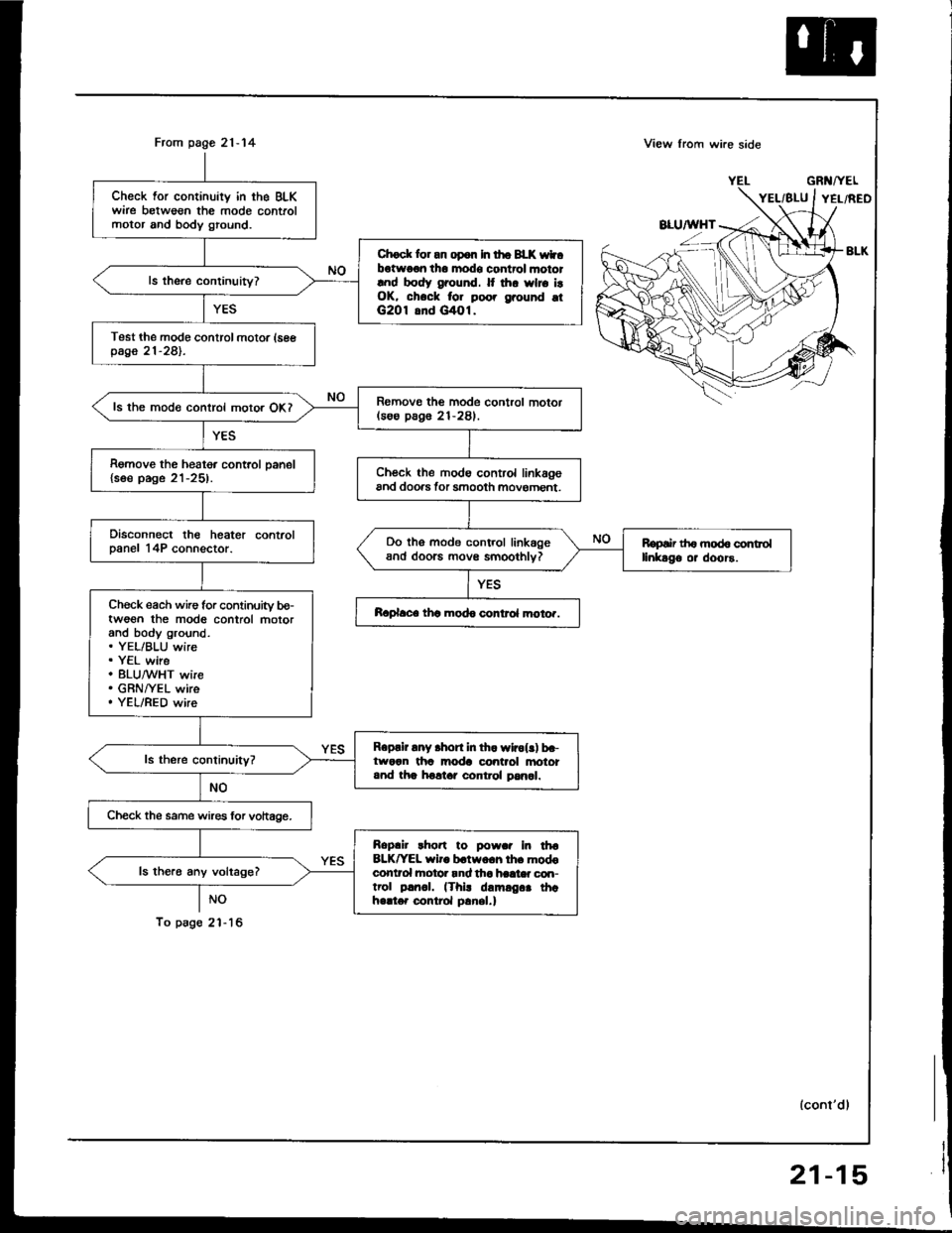
Mode Control Motor
21-14
Modo control motor dooa not nm,
or ono oa moto modo arc In_
oporgtivo.
Disconnect th6 mode control mo_
tor 8P connector.
Turn the ignition switch ON (ll).
Measuroth€ voltage b€tween tho
BLK/YEL wire terminal (+) and
bodv ground (- ).
R.p.lr op.n In lho BLrrYEL wl..
bctw.rn lha undard!.h fuaa/ru-
l.y box .nd ih. mod! corttol
motor.
Turn the ignition switch OFF.
To page 21-1 5
Page 1052 of 1413

From page 21-14
NO
To psg6 2'l - 16
Check for continuity in the BLKwire betweon the mode controlmotor and body ground.
Chock lor an op6n In tho BLK wtbotwo€n tho modo control mototlnd body ground. It thr wlro i!OK, chock for poo. grouhd otG2O1 8nd G/tOl.
Test the modo control motor (seepage 21-281.
Romovo the mode control motor(soo pag6 21-281.ls the mode control motor OKI
Remove the heater control oanel{soe page 21-25).Ch€ck the modo control linkagoand doo.s tor smooth movoment.
Disconnect the heater controlDanel 14P connector.Do tho mode control linkageand doorc movs smoothlv?Ropair th6 mod6 controllinkago or doors.
Ch€ck each wire for continuity bo-twoon the mod6 control motorand body ground.. YEL/BLU wire. Y€L wire. 8LU,^/VHT wire. GRNI/EL wire. YEL/RED wire
Raplace thc modo control moto..
Roprir any .hort in th. wlrol!) b.-tworn tha moda control anototand tha holtar control pan6l.
Check the same wires lor vohage.
Roplir rho.t to powar In tha8LK^'EL wiro b.two.h lh. modoconlrol hotor rnd tha haat* con-trol p!rr.|. (Thi! damrg.. thahello. control p!nel.)
ls the.6 any voltage?
View lrom wi.e side
GRl{/YEL
lconl'dl
21-15