Page 1001 of 1413
Dashboard
Component Removal/lnstallation (cont'dl
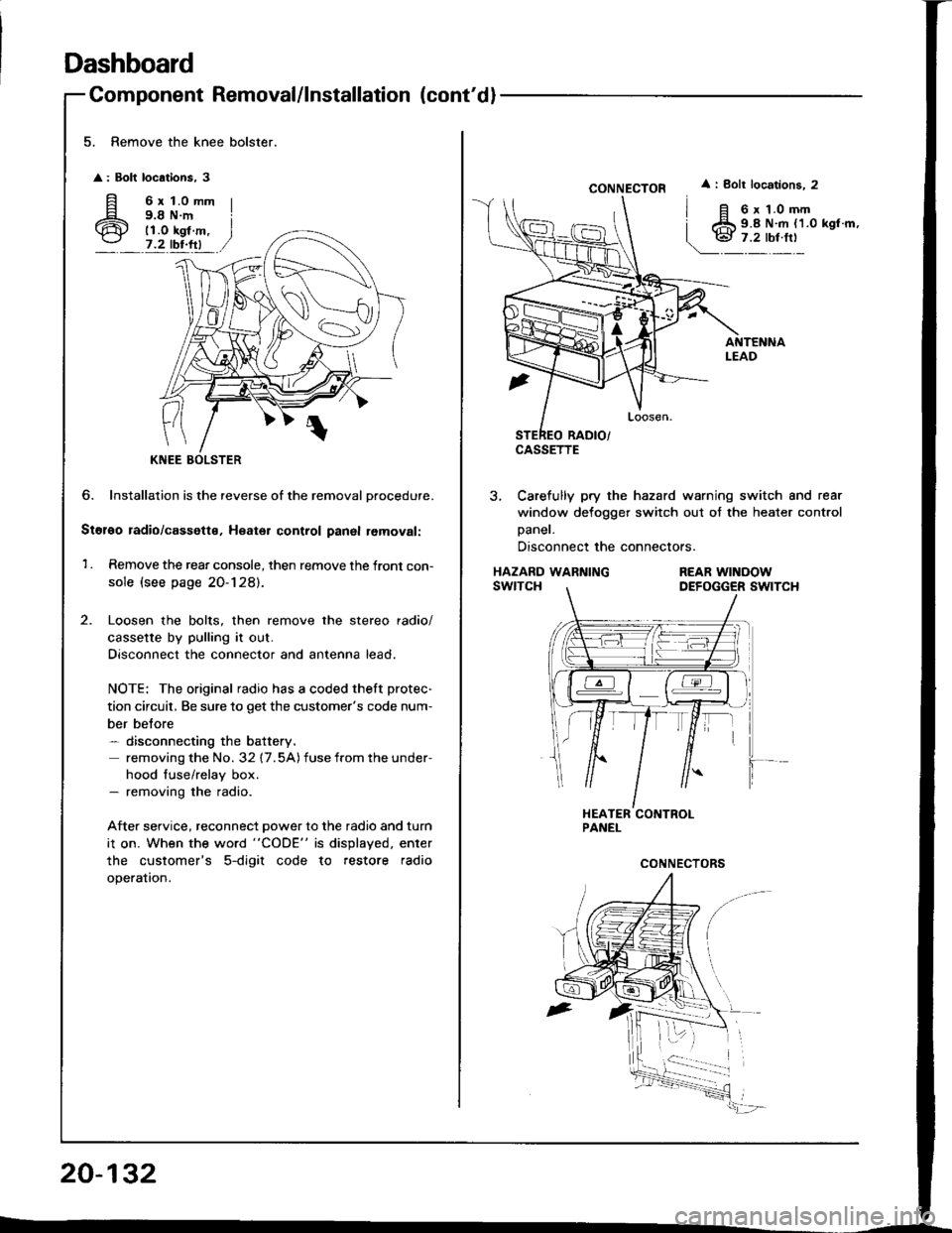
5. Remove the knee bolster.
: Bolt locations, 3
fi 6rt.omm
6 i;i'i#.,7.2 tbr.ftl
?
KNEE
6. Installation is the reverse of the removal Drocedure.
Stol€o radio/cassette, Heater control panal removal:
1 . Remove the rear console, then remove the front con-
sole (see page 20-128).
Loosen the bolts, then remove the stereo radio/
cassette by pulling it out.
Disconnect the connector and antenna lead.
NOTE: The original radio has a coded theft protec-
tion circuit, Be sure to get the customer's code num-
ber belore- disconnecting the battery.
removing the No. 32 17.5A) fuse from the under-
hood fuse/relay box.- removing the radio.
After service, reconnect power to the radio and turn
i1 on. When the word "CODE" is displayed. enter
the customer's 5-digit code to restore radio
operation.
20-132
CONNECTOR
CASSETTE
i Bolt locations. 2
6 x 1.0 mm9.8 N.m {1.0 kgl.m,
3, Carefully pry the hazard warning switch and rear
window defogger switch out of the heater control
Daner.
Disconnect the connectors.
HAZARD WARNINGswtTcHREAR WINOOWDEFOGGER SWITCH
Page 1002 of 1413
4. Remove the screws.
Detach the harness clip and connector clip.
> : Screw locations, 2
Disconnect the air mix control cable from the heat-
er unrt.
AIR MIX CONTROLCABLE
AIR MIX CONTROL
CONNECTOR CLIP
HEATER CONTROL
CABLE
20-133
Pull the heater control panel out, then disco.rEt rhGconneclors.
NOTE: Take care not to bend the atr mtx controlcable.
AIR MIX COI{TROLCABLE
HEATERCONTROIPANEL
7, lnstallation is the reverse o{ the removal procedure.
NOTE: Make sure the connector and air mix con-trol cable are connected properly.
(cont'd)
Page 1003 of 1413
Dashboard
4.
20-134
Component Removal/lnstallation (cont'd
Side air vent .emoval:
Drivsi's
1. Remove the dashboard lower cover (see page
20-1 31 ).
2. Caretully pry the moonroof switch out of the side
air vent, then disconnect the connector.
MOONROOFswrTcH
CONI{ECTOR
SIDE AIRVENT
3, Remove the screw, then remove the side air vent.
< : Clip, hook locatlont
A< : Clip, 1
BV : Hook, 3
lnstallation is the reverse of the removal procedure.
NOTE: Make sure the connector is connected
properly.
> : Sc.6w location,
I
o@)
SIDE AIRVENT
Front passsng€r'�s
Careiully pry the side air vent at the lower edge, then
pull it out.
A : Clip, hook locationg
AA : Clip, 1BV : Hook, 2
Hi
1.'' 11 ,/
SIDE AIRVENT
PROTECTIVETAPE
Sido detoggor t m romoval:
Carefully pry the side detogger trim at the rear edge, then
remove rt.
A : Cllp, hook location!
AA : Clip,lB A: Hook, 1
PROTECTIVE
Page 1004 of 1413
Clock rsmoval:
Caretully pry the clock at the left edge. then pull it out.Disconnect the connector.
CONNECTOR
tl
@
Glove box removal:
'1. Open the glove box.
2. Remove the screw, then remove the damper fromthe glove box.
3. Remove the screw, then remove the glove box.
: Bolt, scr6w locstions
A
: Bolt,
A
6
l^l
)P)
2 B<: Scrow, 1
CLOCK
4. Remove the damper and striker.
>: Nut, icrgw locations
A> : l{ut, 1 B
: Scrow, 2
,-.\'Flot]}lEl\+!lal
_ __,/ *' ,/
5. Installation is the reverse o{ the removal orocedure.
DAMPER
20-135
Page 1005 of 1413
Dashboard
Replacement Precautions
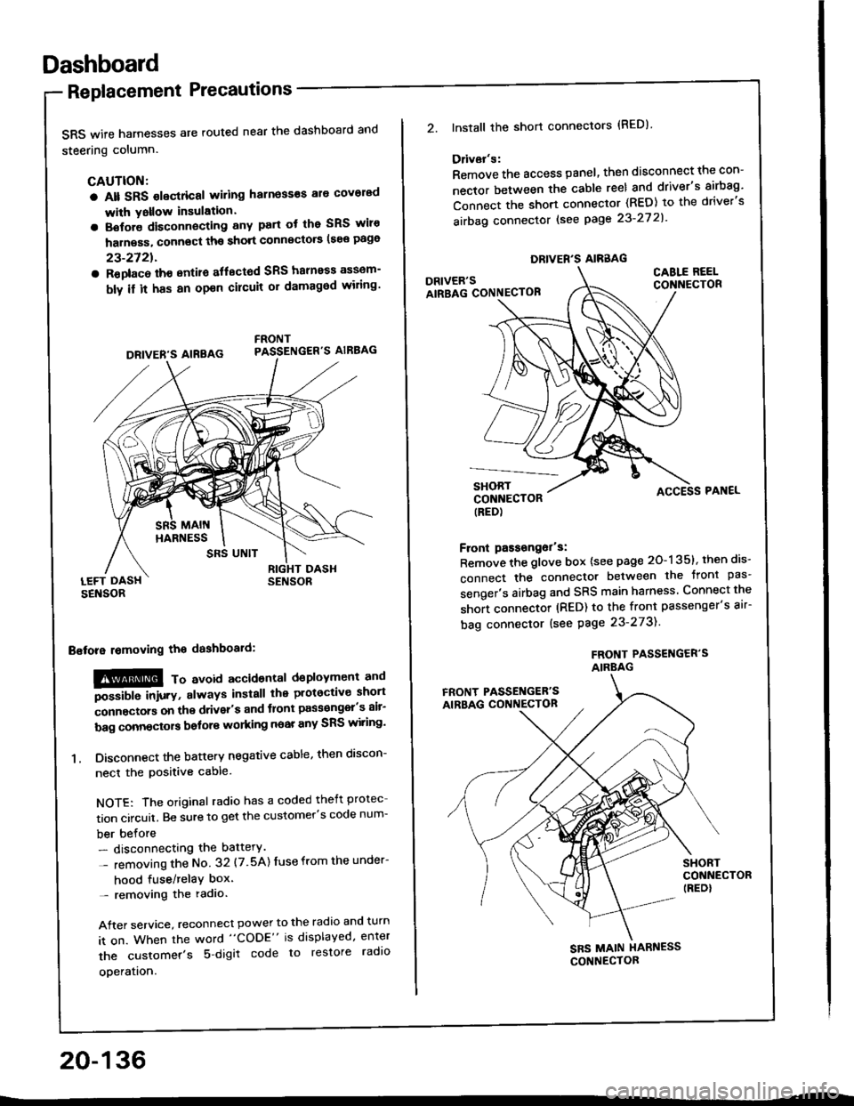
SRS wife harnesses are routed near the dashboard and
steering column.
CAUTION:
a Alt SRS olectrical wiling harness€s ale covorad
with Yollow insulation.
a Botore disconnecting any part ot the SRS wiro
harness, connect ths short connscto6 (see page
23-2721.
a Roplac6 ih€ entiro aflectod SRS halnoss assem-
bly il it has an opon cilcuit or damagod wiling'
LEFT DASHSENSOR
Bstora lomoving the dashboaid:
!@@ To avord accioenlal dsployment and
""iUU inir.v, always install the plotoctive short
;onnectors on the driver's and tlont pass€ngel's air-
bag connectors bolors working near any SRS wiring'
1. Disconnect the battery negative cable, then discon-
necl the positive cable.
NOTE: The original radio has a coded theft protec
tion circuit. Be sure to get the customer's code num-
ber before- disconnecting the battery.
- removing the No 32 (7.5A) Iuse from the under-
hood fuse/relaY box'- removing the radio.
After service, reconnect power to the radio and turn
it on. When the word "CODE" is displayed, enter
the customer's 5 digit code to restore radlo
ooeration.
DRIVER'S AIREAG
SRS UNIT
20-136
DRIVER'S AIRBAG
2.lnstall the short connectors (RED)
Ddvar's:
Remove the access panel, then disconnect the con-
nector between the cable reel and driver's airbag'
Connect the short connector (RED) to the driver's
airbag connector lsee page 23-27 2l'
DRIVER'SAIRBAG CONNECTOB
CABLE REELCONNECTOR
SHORTCONNECTOR(RED)
Front passongor's:
Remove the glove box {see page 20-135}, then dis-
connect the connector between the tront pas'
senger's airbag and SRS main harness Connect the
short connector (RED) to the front passenger's air-
bag connector (see Page 23-273).
FROf{T PASSENGER'SAIRBAG
ACCESS PAI{EL
FRONT PASSET{GER'SAIRBAG CONNECTON
SHORTCONNECTOR(REDI
SBS MAIN HARNESS
CONNECTOR
Page 1006 of 1413
Replacement
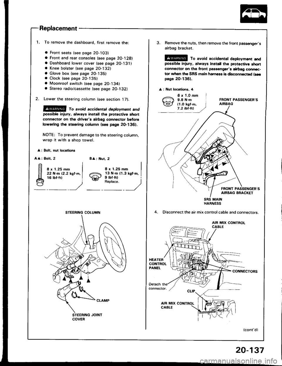
To remove the dashboard, first remove the:
a Front seats (see page 2O-103)
a Front and rear consoles (see page 20-128)a Dashboard lower cover (see page 2O-131)a Knee bolster (see page 2O-132)a Glove box lsee page 2O-135). Clock (see page 20-135)
a Moonroot switch (see page 20-1341a Stereo radio/cassette {see page 20-132)
Lower the steering column (see section 17).
@@ ro avoid accidentat dedoyment andpossiblo in ury, always install the prot€ctive short
connector on tho drivsr's airbag connector bgtor€
lowering tho stooring column (so€ page 20-1361.
NOTE: To prevent damage to the steering column,
wrap it with a shoD towel.
: 8olt, nul locations
A
: Bolt, 28 : ut, 2
8 x 1.25 mm22 N-m 12.2 ksl.m,16 lbt.frl
8 x 1.25 mm
gill$"'l
STEERING COLUMN
3. Remove the nuts, then remove the front passsnger,s
airbag bracket,
@ To avoid accidantar daploym.nr ",'dpossibls iniury, always install th€ protoctiv. 3hqtconnoctor on tho ,ront passongor'a airbag conncc-tor whon tha SRS main ha.na$ is disconncctod llcrpago 20-136).
: Nut locatlons, 4
FRONT PASSENGER'S
FRONT PASSENGER'SAIRBAG BRACKET
4.
SRS MAINHARNESS
Disconnect the air mix controlcable and connectors.
AIR MIX CONTROLCAELE
CONNECTORS
(cont'dl
20-137
Page 1007 of 1413
Dashboard
Replacement (cont'd)
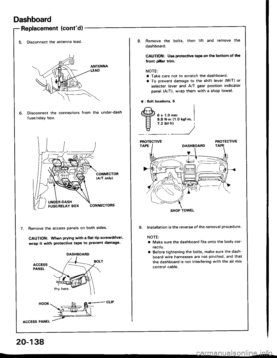
5. Disconnect the antenna lead.
Disconnect the connectors
fuse/relay box.
from the under-dash
CONNECTOR(A/T only)
CONNECTORS
Remove the access panels on both sides.
GAUTION: When prying with 8 tlat tip scrowdrivor'
wrap it with protective tapo to pl€vent damaga'
accEssPANEL
6.
DASHBOARD
HooK ___E-- RE=-cLrP
ffiL
lcCesS Plnel /
20-138
8.Remove the bolts, then lift and remove the
dashboard.
CAUTION: Use protoctive tspe on the bottom ol tha
lront tillar trim;
NOTE:
a Take care not to scratch the dashboard.
a To prevent damage to the shift lever (M/T) or
selecter lever and A/T gear position indicator
panel (A/T), wrap them with a shop towel.
V : Bolt locations, 6
6 x 1.0 mm9.8 N.m (1.0 kgt'm, I7.2 tbt.ftt
____/
PROTECTIVE
9. lnstallation is the reverse of the removal procedure
NOTE:
a Make sure the dashboard fits onto the body cor-
rectly.
a Before tightening the bolts, make sure the dash-
board wire harnesses are not pinched, and thal
the dashboard is not interfering with the air mix
control cable.
SHOP TOWEL
Page 1008 of 1413
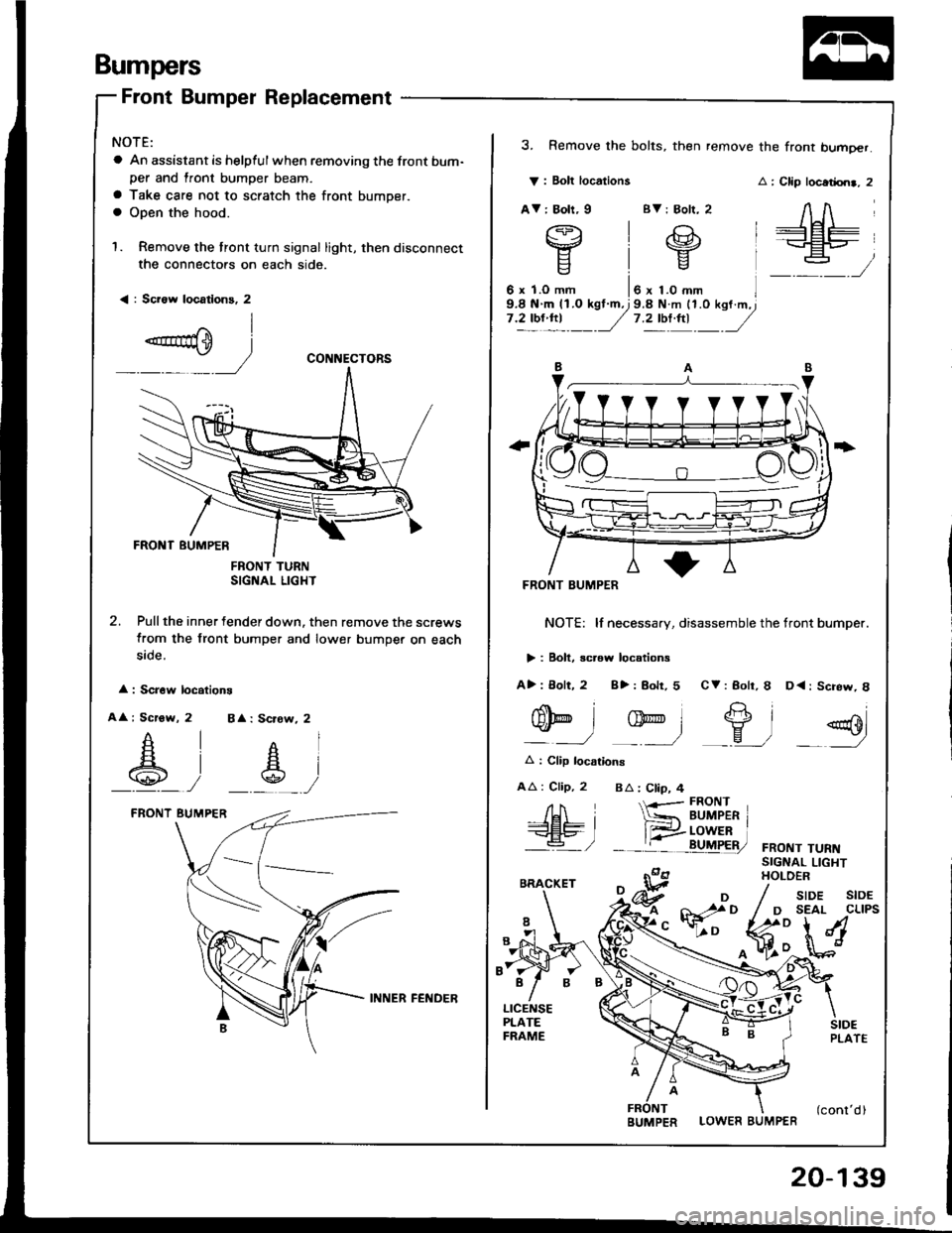
Bumpers
Front Bumper Replacement
NOTE:
a An assistant is helpful when removing the front bum-per and lront bumper beam.
a Take care not to scratch the front bumper.a Open the hood.
1. Remove the tront turn signal light, then disconnect
the connectors on each side.
< : Sci6w locatlons, 2
FNONT TURNSIGNAL LIGHT
2. Pull the inner fender down. then remove the screws
from the front bumper and lower bumper on each
5rcte.
: Scr6w locations
A : Scrow, 2 BA: Scrow, 2
_A_, __s_,
CONNECTORS
V : Bolt locations
AV: Boh, I BV: Bolr, 2
3. Remove the bolts, then remove the front bumoer.
: Clip locadrn., 2
AA
+Et=-+EP_
:
FRONT BUMPER
NOTE: lf necessary, disassemble the tront bumper.
> : Boll, screw locations
A>: 8olt, 2 8>: Bolr, 5 CV: Bolr, I D<: Screw, 8
nolt
gD
Et2"'l-eo
q-l -ry-l _9, =g
A : Clip locarions
AA : Clip, 2 BA : Ctip, 4
FRONT TURNSIGNAL LIGHTHOLOER
/H i-<€L9- I'a- /
{-r-- FRONT
*= BUMPER r
__tr:i!uF&,
LOWER BUMPER
/ sroe stoE
/ D SEAL CLIPS
fr:**M
INNER FEl{DER
BUMPER
20-139