Page 1317 of 1413
Moonroof
Gomponent Location lndex
a All SRS oloctrical wiring harnesses aro covared withyellow insulation,
a Eoforo disconnocting any part of tho SRS wire har-neaa, connoct th6 shon connector(sl.a Roplace th6 entire 8ff6cted SRS harness assombly ifit has an open circuit or damaged widng.
MOO BOOF SWTTCHRemov8l, page 23-214Test, page 23-215
SRS MAIN HARI{ESS{Covered with yellow insulation)
MOO ROOF MOTORTest, pag€ 23-215Replacoment, section 20
23-211
Page 1348 of 1413
Cruise Control
MAIN SWITCHTest, page 23-250Replacement, page 23-250
Component Location Index
a All SRS 6l6ctrical wiring harnessos aro covorod with
yallow insulation,
a Bofo.6 disconnecting any part of th6 SRS wire har-
ness, connoct th€ shon conneclor(s).
a Replaco the ontiro affected SRS halness assombly if
it has an op€n circuit or damagod widng.
SRS MAIN HARNESS(Cov.rod wilh yollow In.ulation)
CRUISE LIGHT(Built into gauge assembly)Bulb Locations, page 23-115
SET/RESUME SWITCHTest. page 23-248Repfacemont, page 23-248
BRAKE SWITCHTest. page 23-251
CLUTCH SWITCH (M/TI
Test, page 23-251
CRUISE CONTROLfnput Test, page 23-246A/T GEAR POSITIOI{swtTcHTest, page 23-136, 252
23-242
Page 1352 of 1413
Cruise Control
Control Unit Input Test
CAUTION:
a All SRS olectrical wi ng harnessos are covored with
yellow insulation.
a Botore disconnecting any part of th6 SRS wire har-
neaa, connect the short connoctor(sl.
a Roplace the €ntir€ affectod SRS hamass assembly il
il has an opan circuit or damaged wifng.
1 , Remove the dashboard lower cover and knee bolster(see page 23-70).
2. Disconnect the 14-P connector trom the control unit.
Insoect the connector and socket terminals to be
sure they are all making good contact.
a lf the terminals are bent, loose or corroded, repair
them as necessary, and recheck the system.
a It the terminals look OK, make the following in-
Dut tests at the connector.- It any test indicates a problem, find and cor-
rect the cause. then recheck the svstem.- lf allthe input tesls prove OK, the control unit
must be faulty; replace it.
CRUISE CONTROL UNIT
14-P COI{NECTOR
SRS MAIN HARNESS
23-246
Viow from wire side
Page 1354 of 1413

Cruise Gontrol
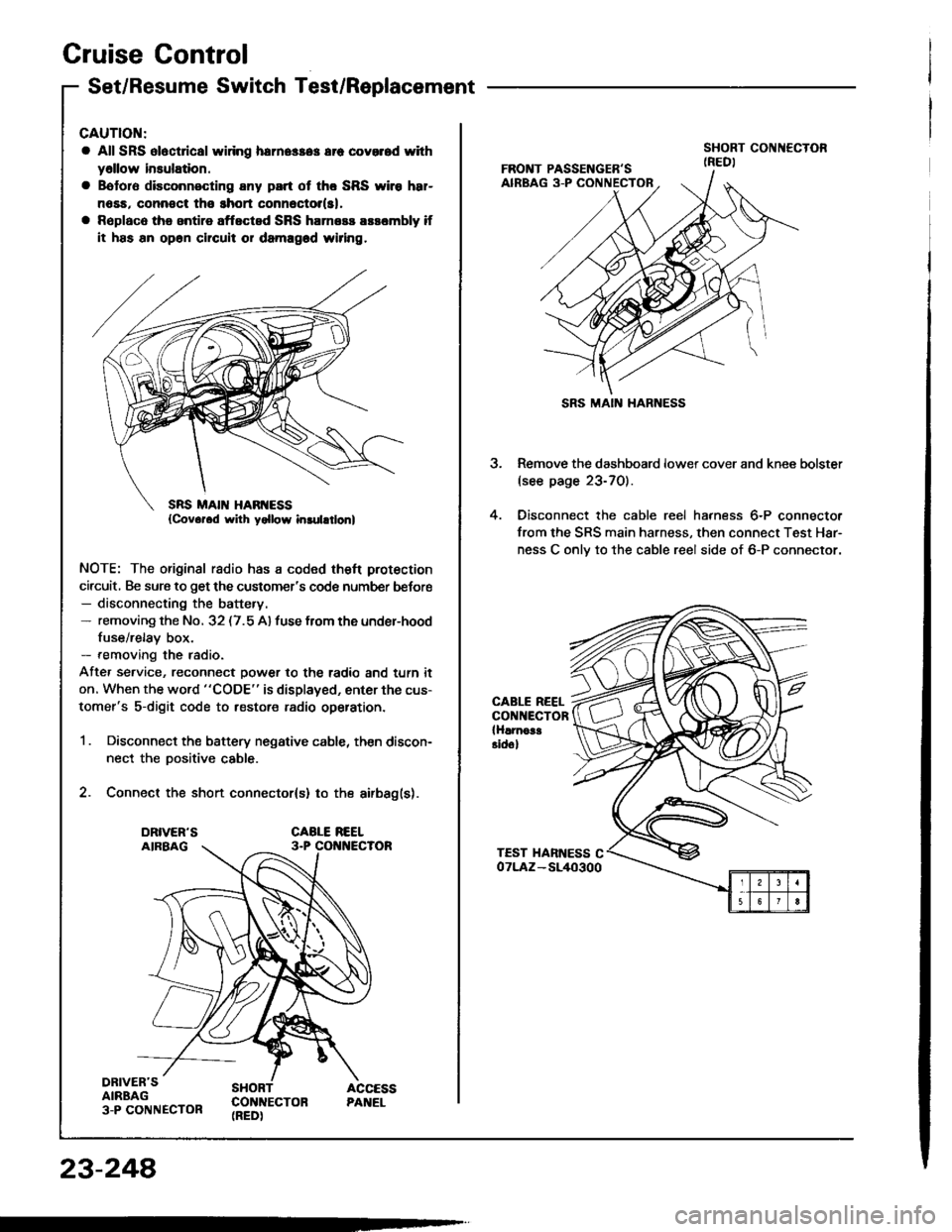
Set/Resume Switch Test/Replacement
CAUTION:
a All SRS ol6ct cal widng herne$a3 err covorod with
y6llow insulation.
a Bototo disconnecting any part ot tho SRS wiro h8r-
n6sa, connoct tho ghort connector(sl,
a Rsplaco the antire aftected SRS harness arsombly if
it has an op6n chcuit or damagod wiring.
NOTE: The original radio has a coded theft protection
circuit, Be sure to get the customer's code number befor€- disconnecting the battery.- removing the No. 32 (7.5 A) fuse from the under-hood
fuse/relay box.- removing the radio.
Afte, service, reconnect power to the radio and turn it
on. When the word "CODE" is displayed, enter the cus-
tomer's s-digit code to restore radio op€ration.
1 . Disconnect the battery negative cable, then discon-
nect the Dositive cable.
2. Connect the short connector(s) to the airbag(s).
DRIVER'SAIRBAG3-P CONNECTOR
SHORT ACCESSCON]TECTON PANEL(REDI
23-248
SRS MAIN HARNESS
3. Remove the dashboard lower cover and knee bolster(see page 23-70).
4. Oisconnect the cable reel harness 6-P connector
from the SRS main harness, then connect Test Har-
ness C onlv to the cable reel side of 6-P connector.
CABLE REELCONNECTORlHlrnoa!Eidol
Page 1355 of 1413
5. Check lor continuity between the terminals of Test
Harness C in each switch position according to the
table.
a lf there is continuity, the switch is OK.
a lf there is no continuity, go to step 6.
6, Remove the cover carefully by prying between the
cover and the switch in the sequence shown.
Terminal
Position
2
SET IONIo----o
RESUME {ONIo----o
CRUISECONTROLSET-RESUMEswtTcH covEF
t
23-249
7. Remove the two screws and remove the switch.
8. Check lor continuitv between the terminals in each
switch position according to the table.
a lf there is no continuity in any position, rsplace
the switch,
a lf thsre is continuity in every position, replace the
cable reel (see psge 23-302).
Tominal
Position
AA'B
OFF\_r-
SFT (ON)o--o
RESUME ION)o----o
Page 1363 of 1413
Wipers/Washers Switch Replacement
a All SRS electrical wiring harnesses ale covered withyellow insulation.
a Beloro disconnecting the SRS wif6 harnoss, install theshort connector(sl.a R€place the entire atlscted SRS hamess assombly ilit ha6 an open citcuii ot damaged wiring.
Remove the steering column covers.
UPPER COVER
A-P CONNECTOR
Disconnect the 8-P and 6-p connectors from theswitch.
Remove the two sctews and the switch.
wIPERS^IITASHEBS SWtTCl.t
A-P CONNECTOR 6-P CONNECTOR
4. Install in the reverse order of removal.
23-257
Page 1364 of 1413
Wipers/Washers
Wipers/Washers Switch Test
5
4
CAUTION:
a All SRS electrical wiring harn6ss6s alo covered with
yellow insulation.
a Belore dkconnecting any part ot th6 SRS wire har-
neaa. connect the short connoctor(sl.
a Replac6 the 6ntire affoctod SRS harness assembly it
it has an open cilcuit 01 damaged wiring.
1. Remove the steering column covers.
2. Disconnect the 8-P and 6-P connectors Jrom the
swatch.
It necessary, remove the two screws and the switch.
Check for continuitv between the terminals in each
switch position according to the table.
scREws
SRS iIAIN HARNESS
{Covor.d rvilh yollow inrulation}
IJK ABCD
23-258
Page 1372 of 1413
Supplemental Restraint System (SRS)
Component Locirtion Index
UNDER.DASHFUSE/RELAY BOX
SRS INDICATOR LIGHT(ln th6 gaug6 assembly)Troubleshooting, page 23-276Gauge assembly, page 23-113
CABLE REELReplacement,page 23-301
AIRBAGBeplacement, page 23.295
SRS UNIT (lncluding cowl sensorl
SRS MAIN HARNESS-FRONT PASSENGER'S AIREAGBRANCH lExc€pt Caned. RS modol)
To CRUISE CONTROLSET/RESUME SWITCH
RIGHT DASH SENSORReplacement, page 23-305
FRONT PASSENGER'SAIRBAGlExcept Canads RS model)Replacement, page 23-295Disposal, page 23'299
LEFT DASH SENSORReplacement, page 23-305
23-266
Replacement, page 23-307