Page 1393 of 1413
Supplemental Restraint System (SRS)
Troubleshooting (cont'd)
Modg C: Shon in one cowl son3ol, or open in both dash
sensors
Mode D: Open in ono da3h sensol
NOTE: The original radio has a coded theft protection
circuit. Be sure to get the customer's code number
before disconnecting the battery cables
1. Disconnect the battery negative cable and then the
positive cable. Then connect the short connector(s)
to the airbag(s) (see page 23'2721.
2. Connect Test Harness B between the SRS unit and
SRS main harness 18-P connector.
23-2AA
3. Measure the resistance between the left dash sen-
sor terminals 812 and 816, and between the right
dash sensor terminals 84 and 86.
lf resistance is more than 5 kO for eiiher set of
terminals, go to step 4.
lf resistance is less than 5 kO tor both sets of ter-
minals, the SRS unit is faulty. Substitute a
known-good SRS unit and recheck the voltages
according to the chart on page 23-283.
Page 1394 of 1413
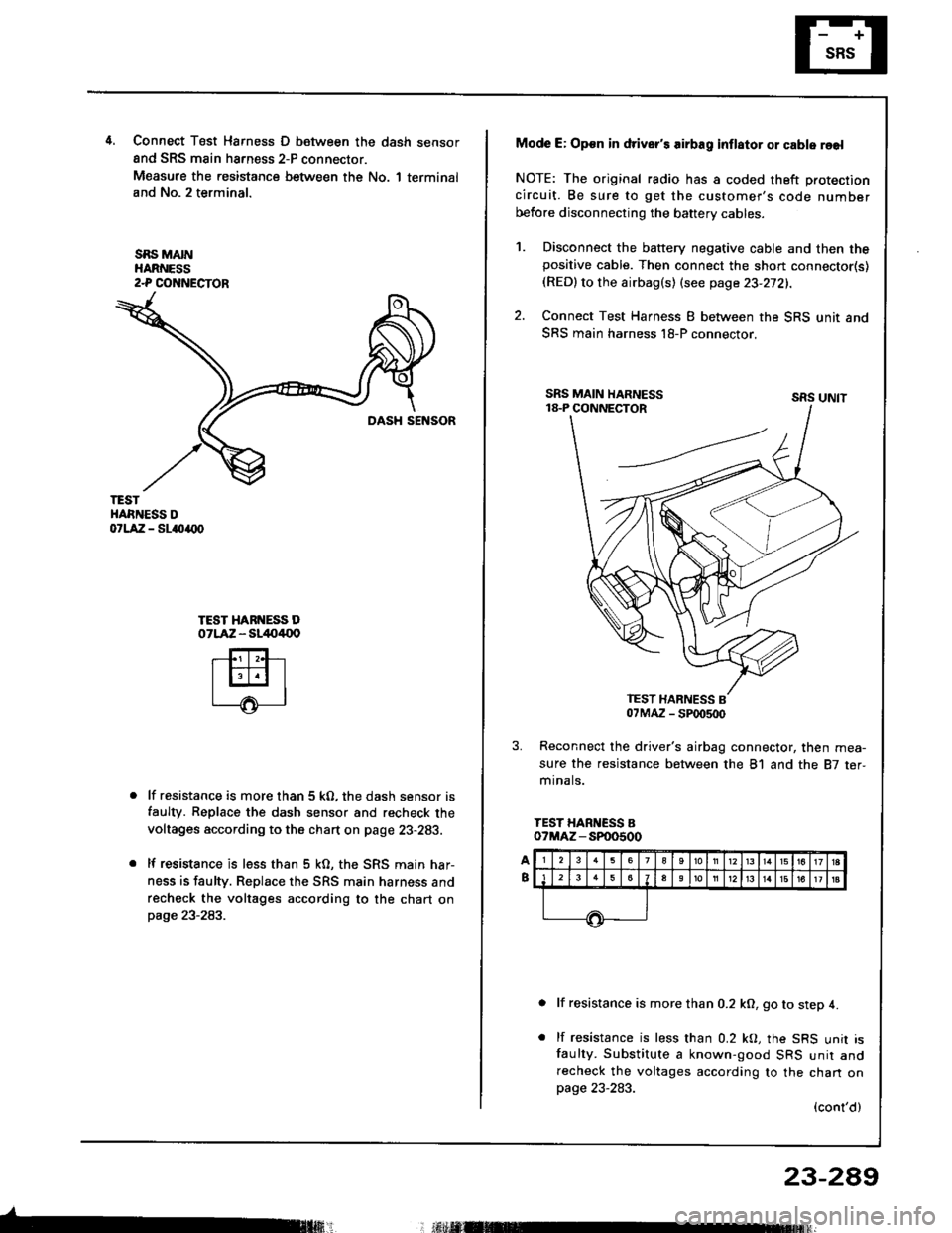
4.Connect T6st Harness D between the dash sensor
and SRS main harness 2-P connector.
Measure the resistance between the No. 1 terminal
and No. 2 terminal.
SBS MAINHARNESS2-P COI{NECTOR
TESTHARNESS DorlA:a - sl{tarx)
TEST HARI{ESS DOTLAZ - sl/to4{lo
lf resistance is more than 5 kO, the dash sensor is
faulty. Replace the dash sensor and recheck the
voltages according to the chart on page 23-283.
lf resistance is less than 5 kO, the SRS main har-
ness is faulty. Replace rhe SRS main harness and
recheck the voltages according to the chart onpage 23-283.
Mode E: Op€n in driver's airbag inflator or cable reel
NOTE: The original radio has a coded theft protection
circuit. Be sure to get the customer's code number
before disconnecting the baftery cables.
Disconnect the battery negative cable and then thepositive cable. Then connect the short connector(s)(RED)to the airbag(s) (see page 23-272).
Connect Test Harness I between the SRS unit and
SRS main harness l8-P connector.
sRs uNtt
Reconnect the driver's airbag connector, then mea-
sure the resistance between the 81 and the 87 ter,mr na ls.
TEST HARNESS Bo?MAZ - SP00500
lf resistance is more than 0.2 kO, go to step 4.
lf resistance is less than 0.2 kO, the SRS unit isfaulty. Substitute a known-good SRS unir andrecheck the voltages according to the chan onpage 23-283.
(cont'd)
23-289
; r.il M
1.
2.
Page 1395 of 1413
Supplemental Restraint System (SRS)
Troubleshooting {cont'd}
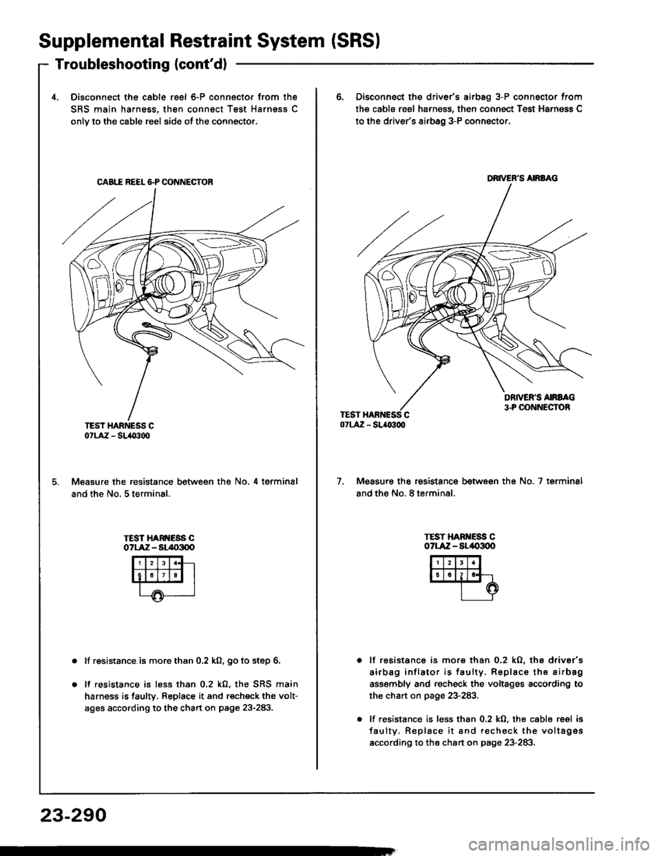
4, Disconnect the cable reel 6-P connector from the
SRS main harness, then connect Test Harness C
onlv to the cable reel side ot the connector.
CAB1I REEL &P CONNECTOB
TEST HARNESS C07LAZ - SLIO300
Measure the resistance between the No. 4 terminal
and the No, 5 terminal.
TEST HARI{ESS COTLAiZ - Sl/t{r3q)
lf resistance.is more than 0.2 ko, go to step 6.
It resistance is less than 0.2 k0, the SRS main
harness is faulry. Replace it and recheck the volt-
ages according to the chart on page 23-283.
23-290
6. Disconnect the driver's airbag 3-P connsctor from
the cabls reol harness, then connoct Test Harn6ss C
to the driver's airbag 3-P conn6ctor.
DRIVER'S AIRBAG
7.Measure the resistance between the No. 7 terminsl
and the No. 8 terminal.
TEST HARI{ESS COTLAZ - AL/|{,3OO
lf resistance is more than 0.2 kO, ths drivsr's
airbag inflator is faulty. Replace the airbsg
ass€mbly and recheck the voltages according to
the chart on page 23-283,
lf resistance is less than 0.2 kO. the cable reel is
faulty. Replace it and recheck the voltag€s
according to the chart on page 23-283.
Page 1396 of 1413
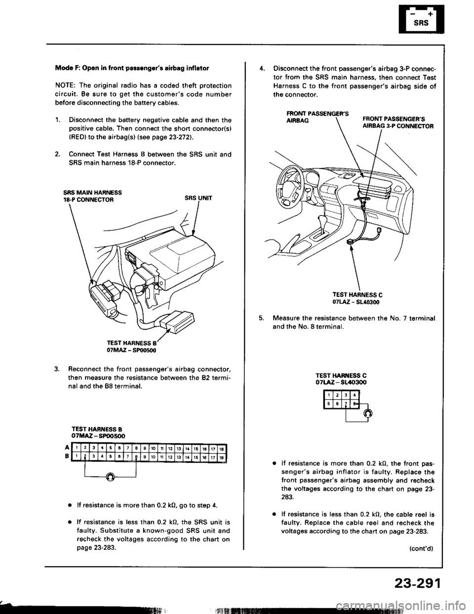
Modc F: Opon in tront pa3s6ngs/s rirbag inflstor
NOTE: The original radio has a coded theft protection
circuit. Be sure to get the customer's code number
before disconnecting the battery cables.
1, Disconnect the battery negative cable and then thepositive cable. Then connect the short connoctor{sl
{RED} to the airbag(s) (see page 23-272).
2. Connect Test Harness B between the SRS unit and
SRS main harness 18-P connector.
SRS UNIT
Reconnect the front passenger's airbag connector,
then measure the resistance between the 82 termi-
nal and the B8 terminal.
TEST HARNESS BoTMAZ - SP005(x)
lf resistance is more than 0.2 k0, go to step 4.
lf resistance is less than 0.2 kO, the SRS unit is
faulty. Substitute a known-good SRS unit and
recheck the voltages according to the chart onpage 23-283.
b
07MAZ - SP|D500
Disconnect the front passenger's airbag 3-P connec-
tor from the SRS main harness, then connect Test
Harness C to the front passenger's airbag sids of
the connector,
FAONT
TEST HARNESS C07LA,Z - SL/O300
Measure the resistance between the No. 7 terminal
and the No. 8 terminal.
TEST HAB ESS C071-Aiz - sll|{,300
lf resistance is more than 0.2 kO, the front pas-
senger's airbag inflator is faulty. Replace the
front passenger's airbag assembly and r€check
the voltages according to the chart on page 23-
243.
lf resistance is less than 0.2 kO, the cable reel is
faultv. Replace the cable reel and r€check the
voltages according to the chart on page 23-283.
(cont'd)
23-291
Page 1397 of 1413
Supplemental Restraint System (SRSI
Troubleshooting {cont'dl
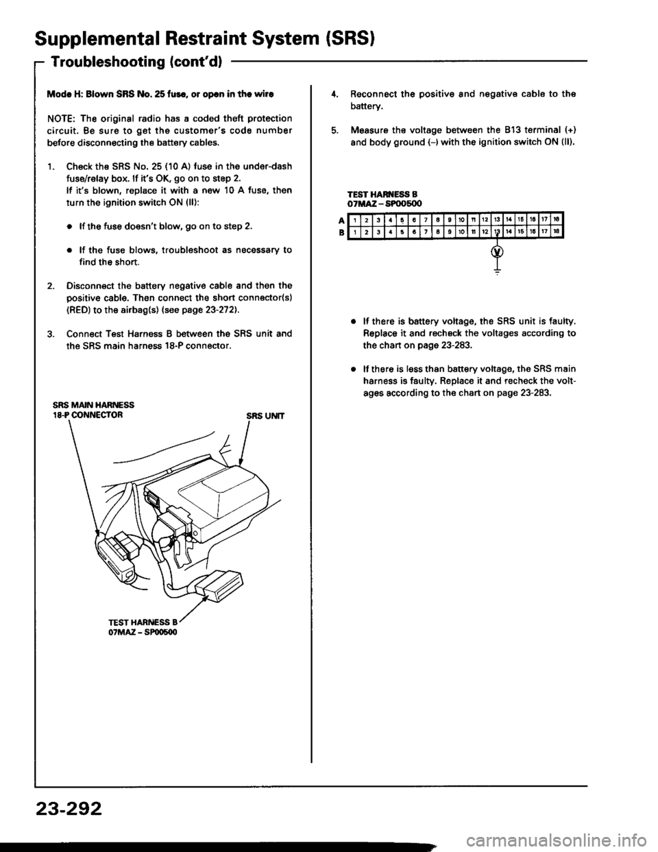
Modc H: Blown SRS No. 25 fur., ol opcn in the wire
NOTE: The original radio has a coded theft protection
circuit. Be sure to get the customer's code number
betore disconnecting the battery cables.
1. Ch€ck the SRS No. 25 (10 A) fuse in the under-dash
fuse/relay box. lf it's OK, go on to step 2.
lf it's blown, replace it with a now 10 A fuse, then
turn the ignition switch ON (ll):
. lf the fuse doesn't blow, 90 on to step 2.
. lf the fuse blows. troublsshoot as necessary to
find th6 short.
2. Disconnect the battery negative cable and then the
positive cable. Then connect the short connector(sl
(RED) to the airbag(s) (see page 23-272).
3. Conn€ct Teat Harnsss B between the SRS unit and
the SRS main harness 18-P connector.
SRS UNIT
23-292
23a7a10nl3161a17ra
26161oll12161a17|a
Reconnect th6 positiv€ 8nd negative cable to the
battery.
Measure ths voltage between the 813 terminal (+)
and body ground {-)with the ignition switch ON (ll).
TEST HAN ESS BoTMA:Z - SPOOs{X'
lf there is battery voltage, the SRS unit is faulty.
Replace it and rscheck the voltages according to
the chan on page 23-283.
lf there is lsss than b8ttery voltage, the SRS main
harness is faulty. Replace it and recheck the volt-
ag6s according to the chart on page 23-283.
Page 1398 of 1413
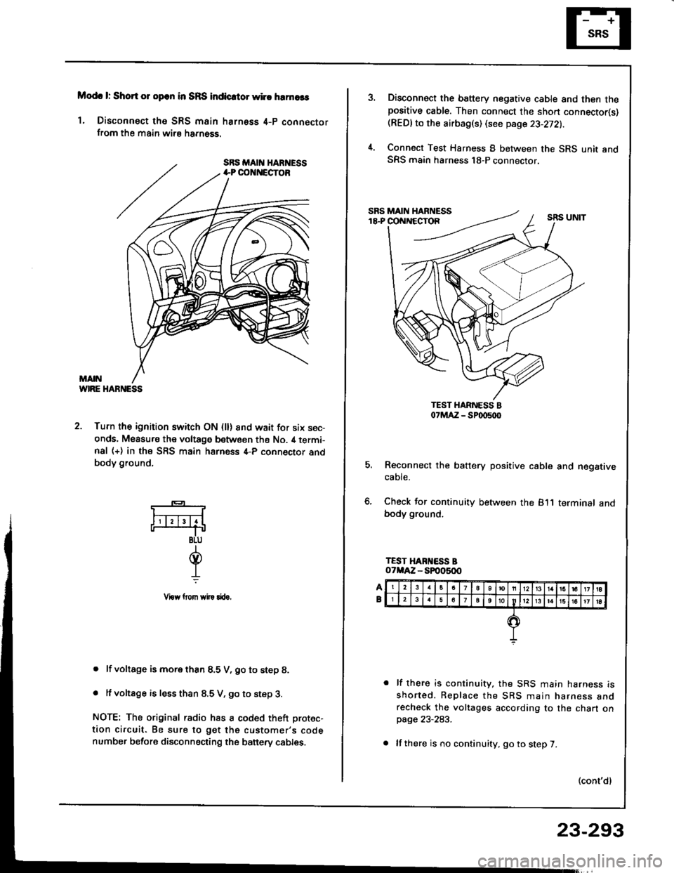
Modc l: Short 01 opcn in SRS indicrtor whc hrrnaas
1. Disconnect tho SRS main harness 4-p connectorfrom the main wirs harn6ss.
WIRE HABNESS
2. Turn the ignition switch ON (ll) 8nd wait for six sec-onds. Measu.s the voltage between ths No. il termi-nal (+) in the SFS main harness 4-P connector andbody ground,
. lf voltage is more thsn 8.5 V, go to step 8.
. It voltage is less than 8.5 V, go to step 3.
NOTE: The original radio has a coded theft protec-
tion circuit. Be sure to get the customer's codenumber before disconnecting the banery cables.
*-
F4
BLU
d.L
Vrow llom wi|! rftro.
Disconnect the battery negative cable and then thepositive cable. Then connect the sho.t connector(s)(REDlto the airbag(s) (see page 23-272).
Connect Test Harness B between the SRS unit andSRS main harness 18-P connector.
5. Reconnect the battery positive cable and negativecaote.
6, Check for continuity between the 811 terminalbody ground.
lf there is continuity, the SRS main harness isshorted. Replace the SBS main narness anorecheck the voltages according to the chart onpage 23-283.
lf there is no continuity, go to step 7.
(cont'dl
23-293
Page 1399 of 1413
Supplemental
Troubleshooting(cont'dl
RestraintSystem (SRSI
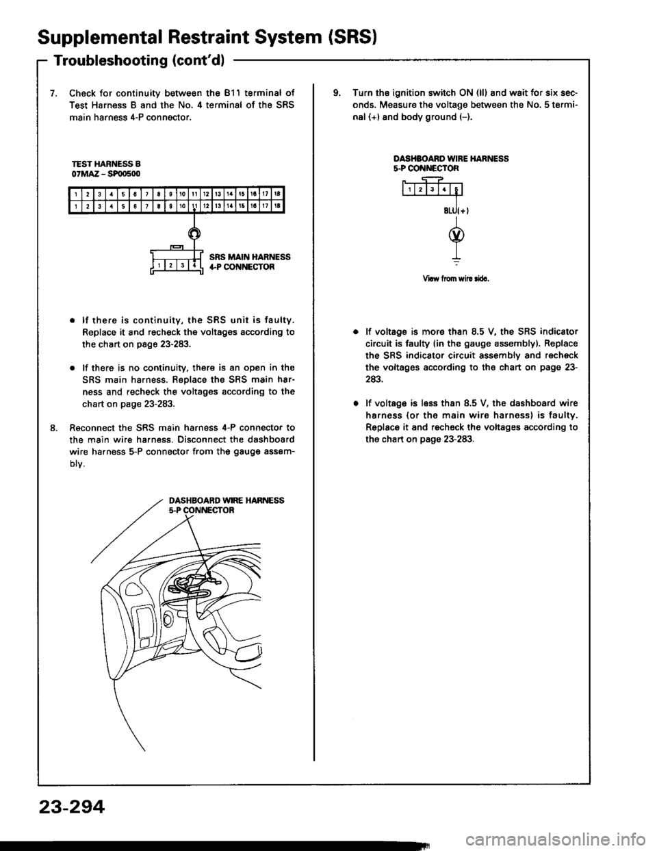
7.Check for continuity between the 811 terminal of
Test Harness B and the No. 4 terminal of the SRS
main harness 4-P conngctor,
oTurn ths ignition switch ON {ll} and wait for six sec-
onds. Measure the voltage between the No. 5 termi-
nal (+) and body ground (-).
TEST HARNESS B07MAZ - SF|D500
OASHSOARO IVIRE HARNESSs.PCO ECTOR
Vraw from sil! rira,
8.
. lf there is continuity, the SRS unit is faulty,
Replace it and recheck the voltages according to
the chart on page 23-283.
. lf there is no cootinuity. there is an open in the
SRS main harness. Replace the SRS main h8r-
ness and recheck the voltages according to the
chart on page 23-283.
Reconnect the SRS main harness 4-P connecto. to
the main wire ha.ness. Disconnect the dashboard
wire ha.ness 5-P connector from the gauge assem-
Dtv.
lf voltage is mora than 8.5 V, the SRS indicator
circuit is faulty (in the gauge assemblyl. Replace
the SRS indicator circuit assembly and recheck
the voltsges according to the chart on page 23-
243.
lf voltage is less than 8.5 V, the dashboard wire
harness (or th€ main wire harness) is faulty.
Replace it and recheck the voltages according to
the chart on page 23-283.
DASHBOARD WIRE HARNESS5.P OONNECTOR
23-294
Page 1400 of 1413
Airbag Assembly Replacement
@E storc a r.movcd lirb.g rslombty with thcp.d surfaco up, if tho lirbrg is improparly 3iorad frcadown, accidontal d.ploymert could plopcl tha unit withcnough torcr lo causc lariour iniury.
CAUTION:
. Do not inst.ll urld SRS plrts trom lnothar c!1,Whon lepairing, uss only now SRS prrt!.o Carefully inlpcct thc airblg rlrcmbly bltorc you
install it. Do not inst.ll an airbag !$.mbly thrt3how! sign3 of bcing droppcd or improparly hrn-dlod, such as dont!. crack3 or dstormation.. Alwry! koop ths rhort connactor(3l (REDI on thaairbrg{s} whon tho hsrnca3 i! dirconnastld.. Do not diras3ombl! or tamp€l with tha lirbrga$ombly.
NOTE: The original radio has a coded th6ft protection
circuit. Be sure to get the customer's code number
before disconnecting the battery cables.
1. Oisconnect the battery nogative cabl6, then discon-nect the positive cable.
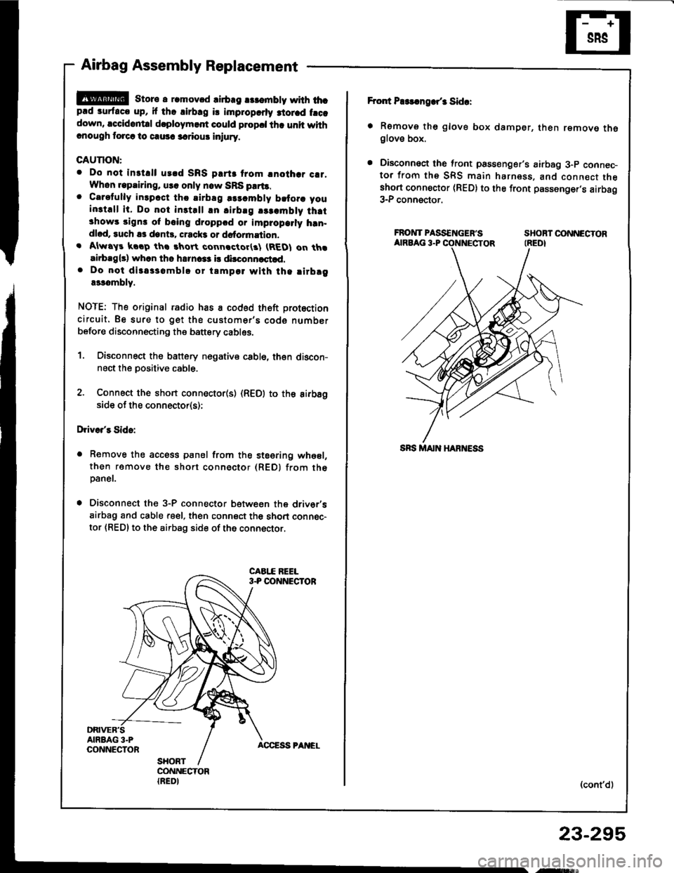
2. Connect the short connecto(s) (R€D) to the aifbagside of the connector(s);
Drivo/s Sido:
a Remove the access panel from the steering whesl,
then ramove the short connector (REDI from th6paner.
. Disconnect the 3-P connector betwesn the driv6r'sairbag and cable reel, then connect th6 short connec-
tor {RED} to the airbag side of the connector.
Fror{ P$!.ngar/3 Sida:
. Remove th6 glove box damper, then remove theglove box.
. Disconnoct the front psssenger's airbag 3-p connec-tor from the SRS main harness, and connect theshort connoctor (RED) to the front passenger,s airbag3-P connector.
FROIVTPASS€NGEF'S SHOBTOONNECTORAIRBAG 3.P CONNECTOR (REDI
(cont'd)
23-295
,ry!$,