Page 133 of 1413

Valve Guides
Replacement (cont'dl
7. Slip a 6 mm {0.2 in) steel washer and the correct
driver attachment over the end of the driver (The
washer will absorb some of the imDact and extendthe life of the driver).
:=:-/--PDRIVER6 mm 10.2 int ATTACHMENTWASHER
Install the new guide(s) from the camshaft side ofthe head; drive each one in until the attachment
bottoms on the head. lf you have all sixteen guides
to do, Vou may have to reheat the head one or twomore times.
Valve Guide Installed Height:
Intake: 12.55 - 13.05 mm {0.49it - 0.51it inl
Exhaust 12.55 - 13.05 mm {0.494 - 0.514 inl
VALVE GUIDE
Reaming
NOTE: For new valve guides only.
1. Coat both reamer and valve guide with cutting oil.
2, Rotate the reamer clockwise the full length of thevalve guide bore.
3. Continue to rotate the reamer clockwise whileremoving it from the bore.
4. Thoroughly wash the guide in detergent and waterto remove any cutting residue.
5. Check clearance with a valve (see page 6-70).
. Verify that the valve slides in the intake and ex-haust valve guides without exerting pressure.
REAMER HANDLE
Turn reamer inclockwise directiononry.
C'
o
a
-'{)
6-72
Page 134 of 1413

Valve Seats
Reconditioning
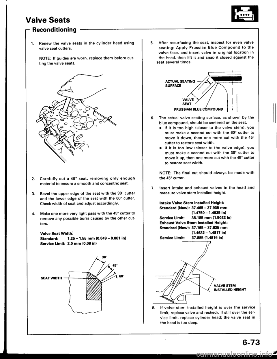
Renew the valve seats in the cylinder head using
valve seat cutters.
NOTE: lf guides are worn, replace them before cut-
ting the valve seats.
Carefully cut a 45o seat, removing only enough
materialto ensure a smooth and concentric seat.
Bevel the upper edge of the seat with the 30' cutter
and the lower edge of the seat with the 60'cutter'
Check width of seat and adjust accordingly.
Make one more very light pass with the 45o cutter to
remove anv possible burrs caused by the other cut-
ters.
Valve Seat Width:
Stlndard: 1.25 - 1.55 mm {0.0,19 - 0.061 in)
Ssrvico Limit 2.0 mm 10.08 in)
SEAI wlDTH
After resurfacing the seat, inspect for even valve
seating: Apply Prussian Blue Compound to the
valve face, and insen valve in original location in
thc hea.l. then lift it and snap it closed against the
seat several times.
ACTUAL SEATINGSURFACE
VALVESEAT
PRUSSIAN BLUE
1.
The actual valve seating surface, as shown by the
blue compound, should be centered on the seat.
. lf it is too high (closer to the valve steml, you
must make a second cut with the 60' cutter to
move it down, then one more cut with the 45'
cutter to restore seat width.
. lf it is too low (closer to the valve edge), you
must make a second cut with the 30'cutter to
move it up, then one more cut with the 45" cutter
to restore seat width.
NOTE; The final cut should alwavs be made with
the 45'cuttef.
lnsert intake and exhaust valves in the head and
measure valve stem installed height.
Intake Vllve St€m ln3tslled Hsighl:
Stsndard (Now): 37.'155 - 37.935 mm
(1.4750 - f .il935 in)
Sorvico Limit: 38.185 mm 11.5033 in)
Exhaust Valvo Stom In3talled Hoight:
Standard (Now): 37.165 - 37.6:15 mm
11.4{X}2 - 1.,1817 inr
Sewico Limit: 37.885 (1.i1915 in)
VALVE STEMINSTALLED HEIGHT
8. lJ valve stem installed height is over the service
limit, replace valve and recheck. lf still over the ser-
vice limit. replace cylinder head; the valve seat in
the head is too deeD.
6-73
Page 135 of 1413
Gylinder Head
Warpage
NOTE: lf camshaft-to-holder oil clearances (see page
6-65) are not within specification. the head cannot be
.esurfaced.
lf camshaft-to-holder oil clearances are within sDecifica-
tions, check the head for warpage.
Measure along edges. and 3 ways across center.
lf warpage is less than 0.05 mm {0.002 in) cylinder
head resurfacing is not required.
lf warpage is between 0.05 mm {0,002 in) and 0.2 mm
{0.008 in), resurface cvlinder head.
Maximum resurface limit is 0.2 mm {0.008 in) based
on a height of 142 mm (5.59 in).
PRECISION STRAIGHT EDGE
Cylindsr Hssd Height:
Standard lNsw): 1i11.95 - 1,f2.05 mm
15.s89 - 5.593 inl
6-74
Page 191 of 1413
NOTE: Use
sembling,
new gaskets and O-rings when reas-
6 x 1.O mm11 N.m 11.1 kgt.m,8.O lbt.ftl
THERMOSTATMOUIITING RUBBERReplace.22-25 N.m 12.2-2.6 ksl.m, 'l6-'19 lbl.ttlECT SWITCH
Thermostat
Replacement
Testing
Replace thermostat if it is open at room temperature.
To test a closed th€rmostat:
SusDend the thermostat in a container of water as
shown.
Heat the water and check the temperature with a
thermometer. Check the temperature at which the
thermostat first opens and at full lift.
CAUTION: Do not let the thelmometer touch the
bottom of the hot container.
Measure the lift height of the thermostat when it's
fullv oDen.
STANDARD THERMOSTAT
Lift height: above 8.O mm (O.31 inl
Starts opening: 169 - 176"F {76-8OoCl
Fully open: 194oF (90oCl
l
THERMOMETER
THERMOSTAT
10-7
Page 334 of 1413

Adjustment
NOTE:
a To check the clutch interlock switch and clutch
switch, see seclion 23.
a The clutch is selt-adjusting to compensate for wear.
CAUTION: It there is no clearanco between the mastel
cylinder piston and push lod. the releaso boaring is held
againsl the diaphragm spring, which can result in clutch
slippage 01 othel clutch problems.
Loosen locknut A, and back otf the clutch switch
{or adjusting bolt) until it no longer touches the clutch
pedal.
Loosen locknut C, and turn the push rod in or out
to get the specified stroke (@) and height (O) at the
clutch pedal.
Tighten locknut C.
Turn the clutch switch (or adjusting bolt) until it con-
tacts the clutch pedal.
Turn the clutch switch (or adjusting bolt) in 3/4 to
1 full turn further.
Tighten locknur A.
7. Loosen locknut B and the clutch interlock switch.
8. Measure the clearance between the tloor board and
clutch pedal with the clutch pedal tully depressed.
9. Release the clutch pedal 15-20 mm {O.59-O.79
in) from the fully depressed position and hold it there.
Adiust the position of the clutch interlock switch so
that the engine will start with the clutch pedal in this
oosition.
1 0. Turn clutch interlock switch 3/4 to 1 tull turn funher.
11. Tighten locknut B.
LOCKNUT B9.8 N.m (1.0 kgf.m, 7 lbf.ftl
CLUTCH INTERLOCKswtrcH
6.
1.
2.
ASSIST SPRING
-6ll
LOCKNUT Cl3 N.m l'l.3 kgf.m, 9
CLUTCH SWITCH{or AOJUSTING BOLTI
LOCKNUT A9.8 {N.ml (1.0 kgl.m, 7 lbt.ftl
(STROKE at PEDALI: 130-140 mm 15.12-5.51 in){TOTAL CLUTCH PEDAL FREE PLAY): 12-21 mm 10.47-0.83 inl including tho p.dal play I -lO mm 10.04-0.39 inl{CLUTCH PEDAL HEIGHTI: 164 mm (6.46 in} to tho lloot{CLUTCH PEDAL DISENGAGEMENT HEIGHTI: 83 mm 13.27 inl minimum to tho lloo.
PUSH ROD
CLUTCH MASTER CYLINDER
Clutch Pedalctutch Pedat I
[-],ll'"-"" f
| :;i:'":fff*tr#:?iff:".,*::,::". | .#::J:::
sb''�'�'""
| |
| "orr,O", It there is no clearanco between the master | ,. aoo""n locknut B and the clutch intertoct switcl. | |cylinder piston and push lod. the releaso boaring is held | | Iagainst the diaphragm spring, which can result in clutch | 8. Measure tne clearance between the floor board and I Islippage 01 othel clutch problems.
I
clutch pedal with the clutch pedal tully deeressed.
I I1. Loosen locknut A, and back otf the clutch switch | 9. Release the clutch pedal 15-2O mm (O.59-O.79 I I
{or adiusting boltl until it no longer touches the clutch I int trom ttre fully depressed position and hold it there. I I
, ::":"" rocknut c, and rurn the push rod in or out | iliiiliffi:l1l:J"'1"-:H"l:tJ:i"i#fT: I I
. il*:*j':"'-(@)andheisht(olatthe
|
,:.;:,nterrockswitch3/4torrurrturnturtner.
I tf
,
::
***r**''
.,".,u"**;
|
'-"'"'';*1,,0*.,.-,.,*,
I I
Page 337 of 1413

Pressure Plate
RING GEAR HOLDER07LAB-PVOOl OO or07924-PD20003
Removal/lnspection
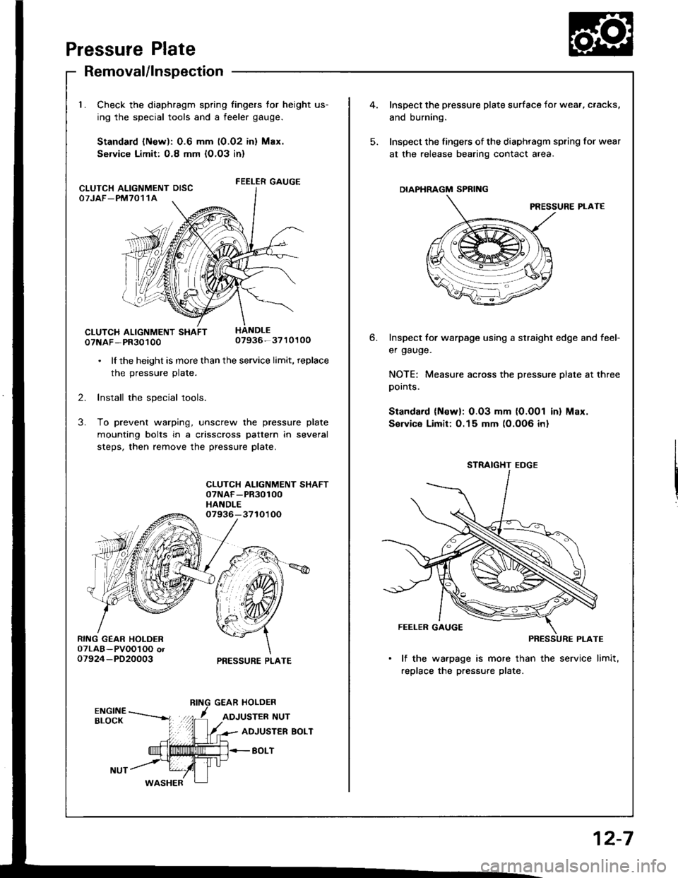
Check the diaphragm spring fingers for height us-
ing the special tools and a feeler gauge.
Standard lNew): 0.6 mm (0.02 inl Max.
Service Limit: O.8 mm {O.O3 in}
FEELER GAUGE
07NAF-PR3010007936-3710100
. lf the height is more than the service limit, replace
the pressure plate.
2. Install the special tools.
3. To prevent warping, unscrew the pressure plate
mounting bolts in a crisscross pattern in several
steps, then remove the pressure plate.
CLUTCH ALIGNMENT SHAFT07NAF-PR30100HANDLE07936-3710'l OO
PRESSURE PLATE
CLUTCH ALIGNMENT OISCOTJAF_PM7011A
4.Inspect the pressure plate surface
and burning.
Inspect the fingers of the diaphrag
at the release bearing contact ar
DIAPHRAGM SPRING
Inspect for warpage using a stru
er gauge.
NOTE: Measure across the prer
pornls.
Standard (Newl: 0.03 mm (0.0
Sorvice Limit:0.15 mm (0.0O6
STRAIGHT EOGE
FEELER GAUGE
PI
lf the warpage is more than
replace the pressure plate.
6.
I surface for wear, cracks,
diaphragm spring for wear
nracr area.
PRESSURE PLAT€
straight edge and feef
pressure plate at three
0.001 in) Max.
)O6 inl
12-7
Page 341 of 1413
spection
release fork boot trom the clutch4. Torque the mounting bolts in a crisscross pattern as
shown. Tighten the bolts in several steps to prevent
warping the diaphragm spring.
8 x 1.25 mm25 N.m 12.6 kgt'm,19 tbt.ftl
2. Remove the release tork trom the clutch housing by
squeezing the release fork set spring with pliers. Re-
move the release bearing.
Check the release bearing for play by spinning it by
hand.
CAUTION: The release boaring i6 packed with
grease. Do not wash it in solvent.
Remove the special tools.
Recheck the diaphragm spring fingers tor height (see
page 12-7]..
Release Bearing
Removal/ln
1. Remove the
housing.
CLUTCH HOUSING
RELEASE FORK
-24/--2,t'.2424?'
IJ
l{ there is excessive plaY, rep)ace the rdease\Ear-
ing with a new one.
,F=:=
Page 601 of 1413
8.Pack the inboard joint with the ioint grease included
in the new driveshaft set.
Grease quantity; 120 - 130 g 11.2 - 4.6 ozl
9. Fit the inboard joint onto the driveshaft.
NOTE;
. Reinstall the inboard joint onto the driveshaft by
aligning the marks on the inboard ioint and the
rollers.
. Hold the driveshaft so the inboard joint points up
to prevent it from falling off.
Left drivoshaft:Align the holder direction of the rollers
toward the slot ot inboard joint as
INBOARDJOINT
/,.-:--\ \
I sotine di,ection
A\
{(@}
HOLDER
10.Adjust the length of the driveshafts to the figure
below. then adjust the boots to halfway between
full compression and full extension.
NOTE: The ends of boots seat in the groove of the
driveshaft and joint.
Left: 475 - 480 mm {18.7 - 18.9 inl
Right: 475 - 480 mm (18.7 - 18.9 inl
lnstall new boot bands on the boots, and bend both
sets of locking tabs.
Lightly rap on the doubled-over portions to reduce
their height.
{cont'd)
11.
16-9