Page 1037 of 1413

Heater and Air Conditioning
Heater ........ 21-1
Air Conditioning .......... ..22-1
SUPPLEMENTAL RESTRAINT SYSTEM {SRS}
The Integra SRS includes a driver's airbag, located in the steering wheel hub. In addition. all models except the
RS model for Canada have a front passenge.'s airbag located in the dashboard above the glovs box. Information
necessary to safely service the SRS is included in this Service Manual. ltems msrk€d with an asterisk (') on the
conlents page include, or are located near, SRS components. Servicing, disassembling or,eplacing thes€ items
will require special precautions and tools, and should therefore be done by an authorized Acura dealer.
a To avoid r6nd6dng tho SRS inoporativo. which could lead to personal injury or dealh in tho svont ot a sevele
frontal collision, all SRS servica work musl b€ portormed by an authorized Acura dealer.
a lmpropor sorvico procaduro3, including incorrect romoval and installatlon of tho SRS, could load to porsonal iniu-
ry causod by uninlonlional activation of tho ailbag8.
a All SRS eloctdcal widng harnossos are covored with yollow in3ulation. Relatsd compononts a.o locatod in tha
stsering column, flont console, daehboard, and dashboafd low6r pan6l, and in lhe dsshboa.d above lh€ glove
box. Do not uao electdcal tost equipmont on theae circuhs.
NOTE: The original radio has a coded theft protection circuit. Be sure to get the customer's code number beto.e
- disconnecting the battery.- removing the No. 32 (7.5 A) luse from the under-hood fuse/relay box.- removing the radio.
After service, reconnect power to the radio and turn it on. When the word "CODE" is displayed, enter the cus-
tomer's 5-digit code to restore radio operation.
Page 1057 of 1413

Blower Unit
Replacement
NOTE: The blower motor, recirculation control motor
and blower resistor can be replaced without lemoving
the blower unit (see page 2l-21).
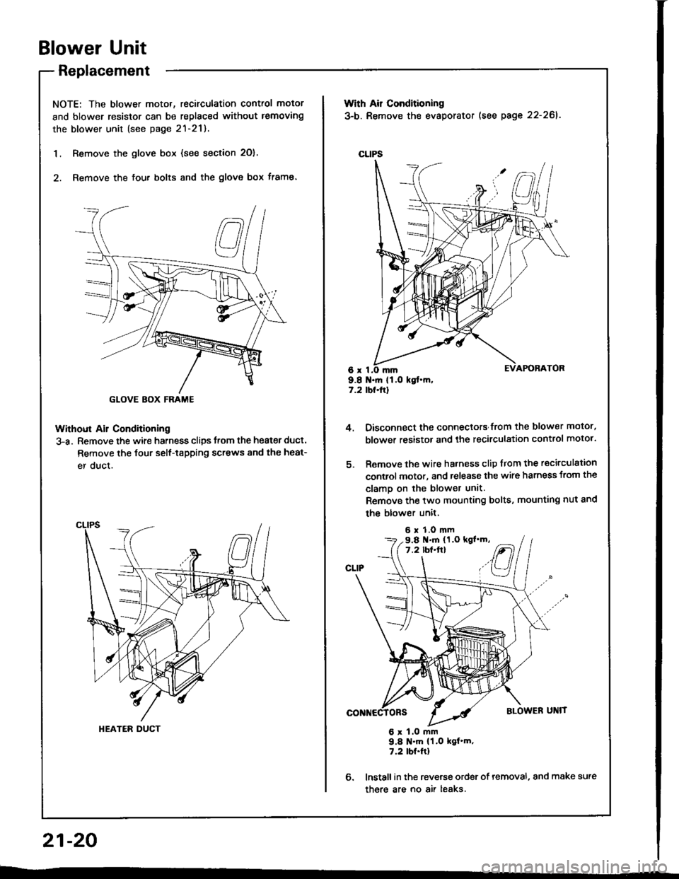
1. Remove the glove box (see section 2O),
2. Remove the fou. bolts and the glove box frame.
Without Ail Conditioning
3-a. Remove the wire harness clips trom the heat€r duct.
Remove the Jour self-tapping screws 8nd the heat-
er duct.
GLOVE BOX FRAME
HEATER DUCT
With Air Conditioning
3-b. Remove the evaporator (see page 22-261.
CLIPS
6x I9.8 .ft 11.O kgt.m,7.2 tbt.ftl
4.
6.
Oisconnect the connectors from the blower motor,
blower resistor and the recirculation control motor.
Remove the wire harness clip from the recirculation
control motor, and release the wire harness from the
clamo on the blower unit.
Remove the two mounting bolts, mounting nut and
the blower unit,
6 x 1.0 mm
6 x 1.O mm9.8 N'm (1.0 kgf'm.7.2 tbt.ftl
lnstall in the reverse order of removal, and make sure
there are no air leaks.
9.8 .m (1.O kgl'm,7.2 lbf'ft}
21-20
--
Page 1094 of 1413

Evaporator
Replacement
CATION:
. All SRS eloctrical wiring harnesses are coverod with
yollow in3ulation.
. B€tore disconnocting 8ny part of tho SRS wire har-
nsss, conngqt th€ 3hort connestor{sl.
. Roplaca ths entire aftected SRS harness a$embly if
it has an op€n circuit or damaged wiring.
lcove.ed with yellow insulation)
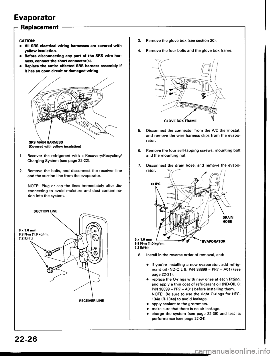
Recover the refrigerant with a Recovery/Recycling/
Charging System lsee page 22-22]-.
Femove the bolts, and disconnect the receiver line
and the suction line from the evaporator.
NOTE: Plug or cap the lines immediately after dis-
connecting to avoid moisture and dust contamina-
tion into the svstem.
2.
L
6x1.0mm9.8 N.m {1.019f.m,1.2 tbl.ttl
SUCTION LINE
RECEIVEB LINE
3.Remove the glove box (see section 20).
Remove the four bolts and the glove box frame.
Disconnect the connector from the Ay'C thermostat,
and remove the wire harness clips from the evapo-
rator.
Remove the four self-tapping screws, mounting bolt
and the mounting nut.
Disconnect the drain hose, and remove the evapo-
rator.
1.
6x1.0mmAPORATOR9.8Nm{1.0kg{.m,7.2 tbtft)
a
a
8. Install in the reverse order of removal. and:
it you're installing a new evaporator, add refrig-
erant oil (ND-OIL 8: P/N 38899 - PR7 - A01) (see
page 22-2'll.
replace the O-rings with new ones at each fitting.
and apply a thin coat of refrigerant oil (ND-OlL 8:
P/N 38899 - PR7 - A01l before installing them.
NOTE: Be sure to use the right o-rings for HFC-
134a {R-134a} to avoid leakage.
apply sealant to the grommets.
make sure that there is no air leakage.
charge the system (see page 22-39) and test its
performance (see page 22-241.
22-26
Page 1107 of 1413

Electrical
Special Tools
Troubleshooting
Tips and Precautions ................................ 23-3Five-stop Tloubleshooting ..............,...-..-... Z3-sSchematic Symbols ................................_. 23-6wire Color Cod€s ..................................... 23-6Relay and Control Unit Locations
Engine Compartment .........,............ ... --. 23-7Dsshboard and Door ..,,......................... 23-gDashboard and Floor ............................. 23-t OOuaner Panel .....-.....23-12Connector ldentification and WireHarness Routing ........ 23-i 3
Index to Circuits and Systems
Airbag ............... ...-..-... 2g-26sAir Conditioning ....,.. Section 2lAltelnator ......_.............. 23-99Anti-lock Brake Systsm (ABS) Section 19Automatic Transmission Section 14Battery .............. .......... 23-66Chafging System ........... 23-98rCigalstte Lighter .....................-...-......-..-.. Z3-2O4Cfock ................. ..........23-197rcruise Controf .......--..-... 23-242Distributor .................... 23-87Fan Controls ................. 23-1ogFuel and Emissions ... Section 1i*Fuses
Under-dash Fuse/Relay Box ................... 23-48Undor-hood ABS Fuse/Retay Box ............ 23-51Under-hood Fuse/Relay Box,.................. 23-52rGauges
Engine Coolant Temperature {ECT)Gauge ................ ..23-126Fuef cauge ............... 2g-123'Gauge Assembly ....--.23-113Speedometer .....-...,,. 23-114Tachometer .....,.....-.. 23-114Ground Distribution ........ 23-60Heater ,,,........,.... ..... Section 2lrHorn ................. ........... 23-199*fgnition Switch ............. 23-70fgnition Syst6m .......-..-.. 23-A7lgnition Timing .............. 23-89Indicator Lights"A/T Gear Position .............. ................... 23-1 32B1ak6 System ...,..,..-.23-127Engine Oil Pressura .............................. _ 23-1 51Low Fuel ............ ......23-125Malfunction Indicator Lamp {MlL} ...,,. Section I l
tfnteglated Control Unit ...29-144*lnterlock System ...................................... 23-1 3gLights, Exteriol
Back-up Lights ........... 23-179Brake Lights .............. 23-t8ltDaytime Running Lights {Csnada} ........... 23-156Front Palking Lights ............................. 23-1 65Flont Side Marker Lights ....................... 23-165Front Turn Signal Lights ........................ 23-1 65*Hazard Warning Lights .........................- 2g-1A4Headlights ................. 23-t6tLicense Plate Lights .............................. 23-1 69Taillights(Harchback) .......... 23-166
{Sedan) .............. .. 23-167Lights. Inteliol
Cargo Area Light {Hatchback) ...... -.. -.. -... 23-177Ceifing Light ........-..-.23-175
Dash Lights Blightness Controt .............. 23-t70Glove Box Lighr ................................... 23-1 69Spotfighr ............ ....-.23-174Trunk Light (Sedanl ............... .............. - 23.-177*Lighting Sysrem .......-.-... 23-152:Moonroof ,,.,.......,..,,,,,.-.23-211PGM-FI Systom ........ S€crion 11Power Distribution .,.-..--..23-54Power Door Locks .............,,..................... 23-233Power Mirors ..,..,....-...- 23-216Power Relays ...........,..... 23-68Power Windows ............ 29-222*Rear Window Defogger ........,... ..........,..... - 23-20,6Reminder Systems
Key-in Remindel System ....,.............,.... 23-1 50Lights-on Reminder System ................... 23-l 5f*Maintenance Reminder system ..,,.... -.. - -. 23-.1 2gSeat Belt Reminder System ..................- 23-125*Side Markel/Turn Signal/Hazard
Ffasher System .,..,..-.23.-1A4Spark Pfugs .........-...-..... 23-97Starting System ....,,.....-. 23-73*Stereo Sound System ...,.......................,,.. 23-l gg
Supplemental Restraint System {SRS} ......... 23-265Vehicfe Speed Sensor {VSS) .............--..-.... 23-122*Wiper/Washer Systom ...............--.........-..- Zg-254
rRead SRS pi€cautions on Page 23-271 betore workingin these areas.
-+
Page 1152 of 1413
Connector ldentification and Wire Harness Routing
Hoator Sub-harneEs A
Hoator Sub-hameEs B
Connoctor or
Terminal
Numb€r of
CavitiesLocationConn6cts toNotog
c671
c672
c673
c674
c675
c676
c677
'lo
2
4
4
14
Under right side ot dash
Under right side of dash
Under right side of dash
Behind glove box
Behind glove box
Behind glove box
Behind middle of dash
Main wire harness (C404)
Main wire harness (C4o3)
Blower motor
Blower resistor
Recirculation control motot
A/C thermostat
Heater sub-harness B (C681)
connoctor 01
T6rminal
Number of
CavitioELocationConnocts toNotos
c681
c682
c683
c684
14
I
6
14
Behind middle of dash
Middle ol floor
Behind middle of dash
Behind middle of dash
Heater sub-harness A (C677)
Mode control motor
Heater Jan switch
Heater conttol Panel
HEATER SUB-HARI{ESS B
23-46
Page 1153 of 1413
Connector ldentification and Wire Harness Routing
UNDER-DASHFUSE/RELAY BOX
SRS Main Harness
Connector or
Terminal
Number ol
CavitiesLocationConnocts tol{otos
c801
c802
c803
c804
c805
c806
c807
2
4
o
18
2
I Behind dashboard lowet cover
J Under left side of dash
Under left side of dash
Middle of floor
Under left side of dash
Under right side of dash
Behind glove box
Under-dash f use/rclay box (C929)
Main wire haness 1C427)
Cable reel
SRS unit
Left dash sensor
Right dash sensor
Passenger's airbag assembly
G801Middle of floorBody ground, via SRS main
harness
23-47
Page 1275 of 1413
License Plate Lights
Replacement
Remov€ the screws and pull out th6 license platelights.
Turn the bulb socket 45o counterclockwise to re-move it from the housing.
ciorG4{t1
Glove Box Light
Test
Remove the glove box and disconnect the 2-p con-neclor.
Check for continuity between the A and B terminals
in each condition according to the table.
BULB(3.4 W)
Condition
T€rminalB
PUSHED {lid closodl
REI"EASED {lid oDen)o-/:\---o\7
ql-----11
dl
23-169
Page 1378 of 1413
Front Pas3enger's Side:
. Remove the glove box damper (see section 20), and
then remove the glove box.
. Disconnect the 3-P connector between the front oas-
senger's airbag and the SRS main harness, then con-
nect the short connector (RED) to the airbag side of
the connector.
SHORT CONNECTOR(REDI
SRS MAIN HARNESS
b,
Disconnecting the SRS Connector at the
Under-dash Fuse/relay Box:
CAUTION: Avoid br.aking the connoctor; it's doubte-
locksd.
1. First lift the connector lid with a thin screwdriver,
then press the connector tab down and pull the con-neclor out.
CONNECTORt_tD
To reinstall the connector. push it into position untilit clicks, then close its lid.
23-273