Page 137 of 1413
Cylinder Head
8 r 1.25 mm2a N..n 12.4lgtm,r 7 tbf.ftl
Installation {cont'd)
4. Install the exhaust manifold and tighten the new
selJ-locking nuts in a crisscross pattern in two or
three steps, beginning with the inner nuts.
. Use new self-locking nuts.
SELF.LOCKING NUT8 x 1.25 mm31 N.m 13.2 kgf'm, 23 lbtltlReplace.
EXHAUST
a.l N.m 14.5 kgt m,33 tbr.trl
GASKETReplsco.
8 x 1.25 mm24 N.m (2.4 kgt m,rt tbfft)
&,x
6-76
5. Install the camshafts, camshaft oil seals and rubber
cap.
NOTE:
. Install the camshafts with keyway facing up.
o Installthe oil sealwith the spring side facing in.
. The oil seal housing surface should be dry,
. Set the O-ring and dowel pin in the oil passage
of th€ No. 3 camshaft holder
Kgyway is lacing up.
Apply liquid gasket around the rubber cap, then
install the rubber cap.
O-RING {ReDlace.)
Page 138 of 1413
7.Apply liquid gasket to the hesd mating surface of
th€ No. 1 and No. 5 camshaft holders on both the
intako and exhaust side. Confirm that the camshaft
koywEys face up, then place those holders, together
with th€ No.2, No. 3 and No.4 camshaft holders,
on th€ cylind6r head.
NOTE: The arrows msrked on the camshaft holders
should point to the timing belt.
INTAKE
t/
bl
ffi
rfl?x
rt
EXHAUST
Apply liquid gaskot
to lh6 3had€d aroas.
Temporarily tighton the bolts of tho camshaft hold-
6rs and thE camshaft holder plates,
lrlo. 6
d
ro
I
CAIISHAFT HOIDERS
Ho. a No.3 1to.2
rllttt
888
CAMSHAFT HOI,I'ER
9. Tighten the bolts in the sequence shown below.
(D - @: 8 x 1.25 mm 27 N.m {2.8 kgf.m,20 lbt ttl
(D - (D: 6 x 1.0 mm 9.8 N.m (1.0 kgrl.m, 7.2 lbf'ft}
10. Install the back cover and camshaft pulleys.
CAMSHAFT
ooooo0o
10 x 1.25 mm56 N.ln l5.t kgf.m,4r lbl.trl
6x1.0mm9.8 N.m 11.0 kgtm, t.2lbf'ft)
(cont'd)
6-77
Page 139 of 1413
11.
12.
13.
Cylinder Head
Installation lcont'd)
lnstallthe timing belt lsee page 6-51).
Adjust the valve clearance (see page 6-44).
Install the rubber seal in the groove of the cylinder
head cover. Seat the seal in the recesses for the
camshaft first, then work it into the groove around
the outside edges.
NOTE:
. Before installing the rubber seal. thoroughly
clean the seal and the groove.
. When installing, make sure the seal is seatedsecurely in the corners of the recesses with nogap.
COVER
6-78
14. Apply liquid gasket to the rubbe. seal at the eightcorne.s of the recesses.
NOTE:
. Use liquid gasket, Part No. 08718 - 0001.. Check that the mating surfaces are clean and dry
before applying liquid gasket.
a Do not install the parts if 20 minutes or more
have elapsed since applying liquid gasket.
Instead,.eapply liquid gasket after removing oldresidue.
r After assembly, wait at least 20 minutes beforefilling the engine with oil.
Apply liquid gasket tothe shaded areas.
Page 140 of 1413
When installing the cylinder head cover. hold the
rubber seal in the groove by placing your fingers on
the camshaft contacting surfaces (top of the semi-
circles).
Once the cylinder head cover is on the cylinder
head, slide the cover slightly back and forth to seat
the rubber seal.
NOTE:
Before installing the cylinder head cover, clean
the cylinder head contacting surfaces using a
shop towel.
Do not touch the pans where liquid gasket was
applied.
6x1.0mm9,8 N.m 11.0 kgt'm,7.2 tffirl
Tighten the nuts in 2 or 3 steps. In the final step'
tighten all nuts, in sequence, to 9.8 N'm (1.0 kgf'm,
7.2 tbf.ft).
After installing, check that all tubes, hoses and con-
nectors are installed correctly.
17.
6-79
Page 141 of 1413

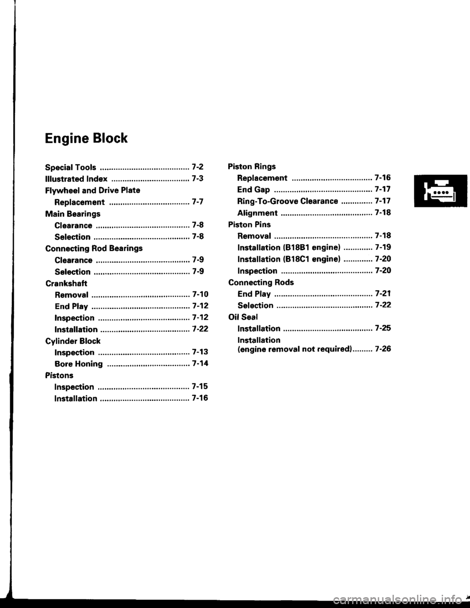
Engine Block
Speciaf Tools .............7'2
lllustrated Index ................................... 7-3
Flywheel and Drive Plate
Repfacement .........7-7
Main Bearings
Clearance ,.............. 7-8
Selection ................ 7-8
Connecting Rod Bearings
Clearance ............... 7-9
Selection ................ 7-9
Crankshaft
Removal .................7-10
End Play .................7-12
lnspection ........,,,.,,7-12
fnstallation .............7'22
Cylinder Block
Inspeetion ..............7-13
Bore Honing .....,.,,.7'14
Pistons
Inspaction ..............7-15
Installation .............7-16
Piston Rings
Replacement .........7-16
End Gap .................7-17
Ring-To-Groove C|earance,,,,.,,,...... 7 -17
Alignment ..............7-18
Piston Pins
Removal ........,........7-18
Installation (818B1 engine) ............. 7-19
fnstaffation (818C1 enginel ............. 7-20
fnspection ..............7-2O
Connecting Rods
End Play .................7-21
Sefeetion ..........,,,,,,7-22
Oil Seal
fnstaffation .............7-25
Installation
(engine removal not requiredl.. .......7-26
Page 142 of 1413
Special Tools
I
Raf. No. I Tool NumbcrDcacriptionOty I Pago Rotcrenc.
o
@
@
@
o
@
o
@
o
@
o
07GAF - PF60300
07HAF - P120102
OTLAD _ PR4O1OA
07LAF - PR30100
07LAB - PV00100 or
07924 - PD20003 or
01924 - PD20002
07948 - S800101
07749 - 0010000
07973 - PE00310
07973 - PE00320
07973 - 5570500
07973 - 6570600
Piston Pin Ease lnsert
Piston Base Head
Seal Oriver
Pilot Collar
Ring Gear Holder
Driver Attachment
Driver
Piston Pin Driver Shaft
Piston Pin Driver Head
Piston Base
Piston Base Spring
1
I
1'I
1
1
1
1
1
1
1
7-14,19,20
1-18, 19,20
7-19,20
7-1
7 -25, 26
7-19,20
1-19.20
1-18, 19, 20
1-18
Eg
o@,a\
o@
@@
0
7-2
Page 143 of 1413

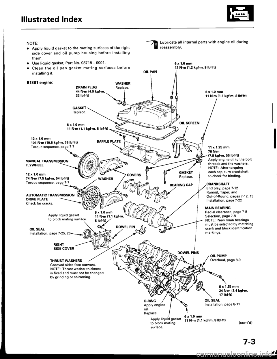
lllustrated Index
NOTE:
. Apply liquid gasket to the mating surfaces of the right
side cover and oil pump housing before installing
them.
. Use liquid gasket, Pan No.08718 - 0001.
. Clean the oil pan gasket mating surfaces before
installing it.
Bl8Bl engine: wAsHEF
Lubricate all internal parts with engine oil during
reassemory.
6x1.0mm12 N.m (1.2 kgf.m,I lbf.ftl
6x1.0mm11 N.m (1.1 kgf.m,8lbtft)
OIL SCREEN
11 x 1.25 mm76 N.m17.8 kgl.m, 56 lbf ftlApply engine oilto the bolt
threads and the washers.NOTE: After torquingeach cap, turn crankshaftto check lor binding.
DRAIN PLUG44 N.m {4.5 kgf.m,33 tbtfr)
GASKETReplace.
6x1.0mm1'l N.m {1.1 kgt.m, I lbtft)
OIL PAN
O.RING
GASKETReplace.
BEARING CAP
12 x 1.0 mm103 N.m (10.5 kgf.m, ?6lbf ft)
MANUALFLYWHEEL
'12 x 1.0 mm74 N.m {7.5 kgt m,54lbf.ftlTorque sequence, page 7 7
DRIVE PLATECheck for cracks,
AUTOMATIC TRANSMISSION
WASHER
6x1.0mm11 N.m {1.1 kgl.m,8 tbf.frt
CRANKSHAFTEnd play, page 7-12Runout, Taper, andOut-of-Round, pages 7 12, 13Instsllation, page 7 22
MAIN BEARINGRadial clearance, page 7-8
Sel€ction, page 7-8NOTE: New main bearingsmust be selected by matching
crank and block identificationmarkrngs.
Apply liquid gasket
to block mating surface.
OIL SEALInstallation, page 7-25,
RIGHTSIDE COVERDOWEL PINSOIL PUMPOverhaul, page 8-9THRUST WASHERSGrooved sides face outward.NOTE: Thrust washer thicknessis tixed and must not be changedby grinding or shamming.
8 x 1 .25 mm2,1 N.m {2.4 kgt m,17 tbt.ft)
OIL SEALInstallation, page 8-11Apply engrneorl.Replace.
Apply liquid gasket
to block mating
6x1.0mm'11 N.m {1.1 kgf'm, 8 lbl ft)(conr'dl
7-3
Page 144 of 1413
lllustrated Index
(cont'd)
NOTE:
. Apply liquid gasket to the mating surfaces of the right
side cover and oil pump housing before installing
thsm.
. Use liquid gask6t, Part No. 08718 - 0001.
. Clean the oil pan gasket mating surtac€s before
innalling it.
Bl8Cl !ngin.:
Lubricate all internal parts with engine oil during
reassemblv.
OIL PAN
DBAIN PLUG4,a N.m la.s tgl.m.33 rbr.ftt
6x1.0mm11 N.m (1.1 kgt m,E |bfitl
6x1.0mmti l*m 11.l kgf m,I tbf.ftl
GASKETReplace.12 x t.0 mlnlo:t N.|n 110.510f'm, tG lbffrlTorque soquonce. page 7-7
BAFFLE PLATE
6xl.0mmll N.m (1.1 kgt m.8 tbt frl
O|L SCAEEN
6 x 1.0 rim11 N.m (1.1 kgf.m,8 tbt ft)
FLWYHEEL
7-4