Page 1353 of 1413

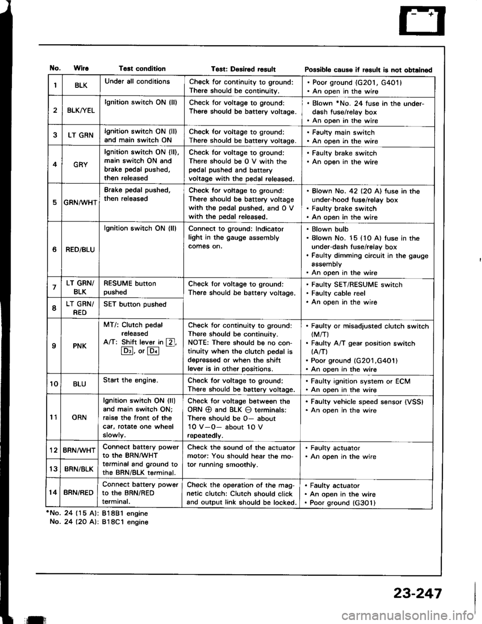
tlo.WlfeTost condition
*No. 24 (15 Al: 81881 engine
No.24 l2O A): 818C1 engine
Tost: Desired rosultPossibl6 caus€ it losult is not obtained
IBLKUnder all conditionsCheck for continuity to ground:
There should be continuitv.
. Poor ground (G201, G4011. An open in the wire
2BLKryEL
lgnition switch ON (ll)Check for voltage to ground:
There should be battery voltage.
. Blown rNo. 24 fuse in the under-
dash fuse/relay box. An open in the wire
5LT GRNlgnition switch ON (ll)
and main switch ON
Check for voltage to ground:
There should be battery volt€ge.
. Faulty main switch. An open in the wire
4GRY
lgnition switch ON lll),main switch ON and
brake pedal pushed,
then released
Check for voltage to g,ound;
There should be O V with thepedal pushed and battery
voltage with the pedal released,
. Faulty brake switch. An open in the wire
GRN/wHT
Brake pedal push€d,
then r€leased
Check tof voltage to ground:
There should be battery voltage
with the pedal pushed, and O V
with the Dedal released.
Blown No. 42 l2O Al tuse in the
under-hood fuse/relay box
Faulty brake switch
An open in the wire
6RED/BLU
lgnition switch ON (ll)Connect to ground; Indicator
light in the gauge assembly
comes on.
Blown bulb
Blown No. 15 (10 A) fuse in the
under-dash fuse/relay box
Faulty dimming circuit in the gauge
assembly
An open in the wire
7LT GRN/
BLK
RESUME button
pushedCheck for voltage to ground:
There should be battery voltage.
Faulty SET/RESUME switch
Faulty cable reel
An open in the wire6LT GRN/
RED
SET button pushed
qPNK
MT/: Clurch pedal
released
A/T: Shift l€ver in [Zl,
lD:I, or lE.l
-
Check for continuity to ground:
There should be continuity.
NOTE: There should be no con-
tinuity when the clutch pedal is
depressed or when the shift
lever is in other positions.
Faulty or misadiusted clutch switch(M/T)
Faulty A/T gear position switch(A/T)
Poor ground (G201 ,G4O1)An open in the wire
10BLUStart the engine.Chsck for voltage to ground:
There should be battery voltage.
. Faulty ignition system or ECM. An open in the wire
11ORN
lgnition switch ON (ll)
and main switch ON;
rsise the front of the
car, rotat€ one wheel
slowly.
Check Jor voltage between the
ORN @ and BLK O terminals:
There should be O- about
10 V-O- about 1O V
repeatedly.
. Faulty vehicle speed sensor (VSSI. An oDen in the wire
'128RN/WHTConnect battery power
to the BRN/WHT
terminal and ground to
the BRN/BLK terminal.
Check the sound of the actuator
motor: You should hear the mo-
tor running smoothly.
. Faulty actuator. An opsn in the wire
13BRN/BLK
14BRN/RED
Connect battery power
to the BRN/RED
terminal.
Check the operation of the mag-
netic clutch: Clutch should click
and output link should be locked.
Faulty actuator
An open in the wire
Poor ground (G3O 1)
il:
23-247
Page 1354 of 1413

Cruise Gontrol
Set/Resume Switch Test/Replacement
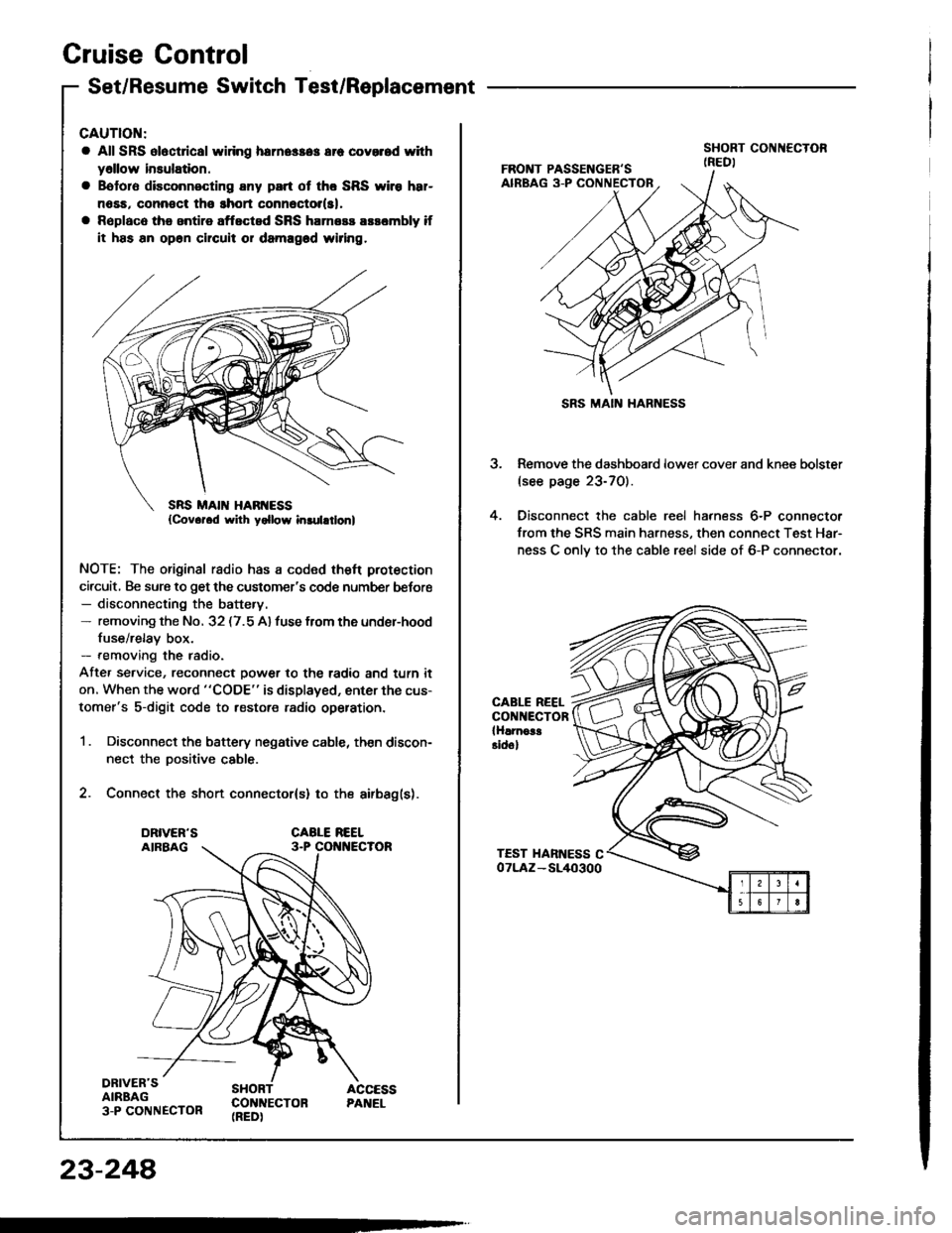
CAUTION:
a All SRS ol6ct cal widng herne$a3 err covorod with
y6llow insulation.
a Bototo disconnecting any part ot tho SRS wiro h8r-
n6sa, connoct tho ghort connector(sl,
a Rsplaco the antire aftected SRS harness arsombly if
it has an op6n chcuit or damagod wiring.
NOTE: The original radio has a coded theft protection
circuit, Be sure to get the customer's code number befor€- disconnecting the battery.- removing the No. 32 (7.5 A) fuse from the under-hood
fuse/relay box.- removing the radio.
Afte, service, reconnect power to the radio and turn it
on. When the word "CODE" is displayed, enter the cus-
tomer's s-digit code to restore radio op€ration.
1 . Disconnect the battery negative cable, then discon-
nect the Dositive cable.
2. Connect the short connector(s) to the airbag(s).
DRIVER'SAIRBAG3-P CONNECTOR
SHORT ACCESSCON]TECTON PANEL(REDI
23-248
SRS MAIN HARNESS
3. Remove the dashboard lower cover and knee bolster(see page 23-70).
4. Oisconnect the cable reel harness 6-P connector
from the SRS main harness, then connect Test Har-
ness C onlv to the cable reel side of 6-P connector.
CABLE REELCONNECTORlHlrnoa!Eidol
Page 1356 of 1413
Cruise Gontrol
Main Switch Test/Replacement
NOTE: Be careful not to damage the switch and the in-
strument oanel.
1. Remove the instrument panel trom the dashboard(see page 23-1 18).
2. Remove the switch from the dashboard, then dis-
connect the 5-P connecto,.
ABCDE
23-250
Tenninrl
P".ii";--\ABD
OFF-oo-/a
ONAA-o\7
3. Ch6ck for continuity betwo€n the terminals in each
switch position according to the table.
a lf thera is no continuity in any position, replace
th€ switch.
A
rxorcaToR y'UCI{T [ (
to.grwl \) ucsr7 lo.grwl
E
Page 1361 of 1413
Circuit Diagram
UNOER- DASHFUSE/RELAY BOX
WHT/ll-X -FWHr
GRX/4X
WII{DSHI€ID WIPERAIVASHER S1VITCH
REAR WINOOWWIPER MOTOR
BLK
{
G30l
REARwtN00wWASHERMOTOR
BLK
G20'IG401
l*_(ittwA!
Y
Mor
|-8LK
I
G30l
UNOER - HOOO FUSENEUY 8OX
si 4.t,,1 /'i;",ry)"'.,
REARWINOOWWIPER/WASHERswtTcH
8LK
G503
8tK
G20rG101
23-255
. : whh comtinad wchar-wllbr olrnlirn
,r-
Page 1371 of 1413
Supplemental Restraint System
(sRst
Gomponent Location Index .................. 23-266
Description ..23-267
Circuit Diagram 23-268
Wiring Locations 23-270
Precautions/Procedures ..23-271
Troubfeshooting ............. ..23-276
Airbag Assembly
Repfacement .................. 23-295
Disposal ....23-299
Cable Reel
Replacement .................. 23-301
Dash Sensor
Replacement .................. 23-305
SRS Unit
Replacement .................. 23-307
Page 1372 of 1413
Supplemental Restraint System (SRS)
Component Locirtion Index
UNDER.DASHFUSE/RELAY BOX
SRS INDICATOR LIGHT(ln th6 gaug6 assembly)Troubleshooting, page 23-276Gauge assembly, page 23-113
CABLE REELReplacement,page 23-301
AIRBAGBeplacement, page 23.295
SRS UNIT (lncluding cowl sensorl
SRS MAIN HARNESS-FRONT PASSENGER'S AIREAGBRANCH lExc€pt Caned. RS modol)
To CRUISE CONTROLSET/RESUME SWITCH
RIGHT DASH SENSORReplacement, page 23-305
FRONT PASSENGER'SAIRBAGlExcept Canads RS model)Replacement, page 23-295Disposal, page 23'299
LEFT DASH SENSORReplacement, page 23-305
23-266
Replacement, page 23-307
Page 1374 of 1413
SRS INOICATOF CIRCUITlln lh6 grugo .$.mblyl
IIIInI llI tltUI
SADH
o
@
o
@
@
a
a
@
a
@
a
@
@
@
a
a
Gircuit Diagram (With Front Passenger's Airbagl
UNOE8- DASHFUSSRELAY BOX
DRIVER'SAIREAGINFI.A]OR
FROI.ITPASSENGER'SAIREAGINFLATOR
UNDERHOODFUSE/REI.AY80x
SRS UNIT l8-P COI'INECTOR
23-269
Page 1375 of 1413
Supplemental Restraint System (SRSI
Wiring Locations
CAUnON: Make sure all SRS ground locrtion3 lrc clrln rnd ground3 tra |.curalv rltachad.
NOTE:
o Alt SRS electricsl wiring harnesses are covered with ysllow insulation.
. RsDlace the entire affected SRS harness assembly if it has an open circuit or damaged wiring.
CABIE REEL to DdrrEFS AnaAC3+ OOI{iECTOR
DASHBOARD WIRE HARNEi9to INDICATOB UGHT in GAUGE ASSEMBLY
5-P CONNECTOBaFs irA[t H^RiEssto FROiIT PASSEMIEFS Ana G3t coftf'Eclon
SRS MAIN HARNESS tO
MAIN WIRE HARNESS+P OONNECTOR
C. b Ra nod.ll
SnS Alt{ ll^ntc8s too sH SErson2+ OOt{tlEcT()R
SRS MAIN HARNESSto UNDER-DASHFUSE/RELAY BOX2"P @NNECTOR
MAIN WIRE HARNESSto DASHBOARD WIREHARNESSlGP CONNECTOR
SBS MAIN HARNESS toLEFT DASH SENSOR2.P CONNECTOA
23-270