Page 1195 of 1413
lgnition Timing Inspection and Setting
1.Start the engine. Hold the engine at 3,00O rpm with
no load (A/T in S or E position, M/T in neutral) until
the radiator fan comes on, then let it idle.
Pull out the service check connector located behind
the right kick panel. Connect the BRN/WHT and BLK
terminals with the SCS short connector.
4. Adiust ignition timing, if necessary, to the follow-
ing specifications:
lgnition Timing:
16 t 2 BTDC (RED) at 75O 1 50 rpm in noutral
NOTE:
a Shift lever must be in neutral.
a All electrical systems should be turned OFF.DATA LINKCONNECTOR {3-P}NOTE: Do not attachthe jumper wire.
POINTER
SCS SHORT CONNECTOR{0?PAZ-O010't 00t
SERVICE CHECK CONNECTOR I2.PINOTE: Located behind the right kickoanel
Connect a timing light to the No.1 ignition wire andpoint it toward the pointer on the timing belt cover.
TIMING LIGHT
lcont'd)
REO MARK
23-89
Page 1196 of 1413
lgnition System
lgnition Timing lnspection and
Setting (cont'd)
5. To adjust ignition timing, loosen the distributor
mounting bolts, and turn the distributor housing
counterclockwise to advance the timing, or clock-
wise to retard the timing.
MOUNN G BOLTS24 N.m (2.4 kgl.m, 17 lbt'ftl
Tighten the adjusting bolts and recheck the timing.
Remove the SCS short connector trom the service
check connector.
2.
ldle Speed Inspection
Shift to neutral or Ll] and start the engine. Hold the
engine at 3,OOO rpm with no load until the radiator
fan comes on, then let it idle.
Connect a tachometer to the test tachometer con-
nector.
ldle sp6od
M/T: 750 t 50 rpm in neuttal
A/T: 75O t 50 rpm in @ or @
NOTE: Allelectrical systems should be turned OFF.
Adjust the idle speed il necessary (see section 1 1).
b.
23-90
Page 1203 of 1413

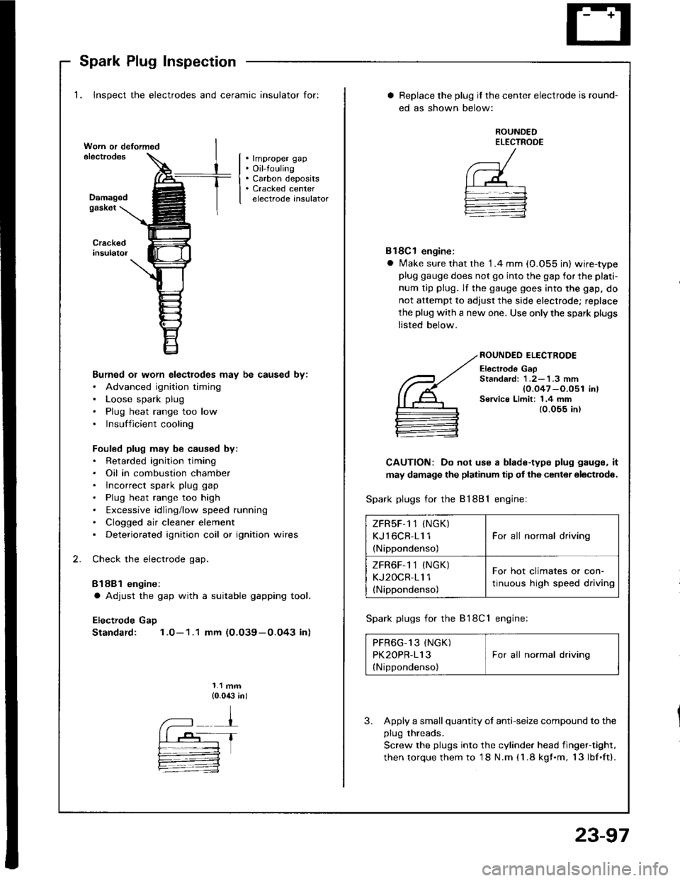
Spark Plug Inspection
1. Inspect the electrodes and ceramic insulator for:
. rmproper gap. Oil-touling. Carbon deposits. Cracked centerelectrode insulatorDamagedgask6t
Burned or worn electlodes may be caused by:. Advanced ignition timing. Loose spark plug. Plug heat range too low. Insufficient cooling
Fouled plug may be caused by:. Retarded ignition timing. Oil in combustion chamber. lncorrect spark plug gap. Plug heat range too high. txcessive idling/low speed running. Clogged air cleaner element. Deteriorated ignition coil or ignition wires
Check the electrode gap.
Bl88l engine:
a Adjust the gap with a suitable gapping tool.
Electrode Gap
Standard: 1.0-1.1 mm (O.O39-0.O43 in)
1.1 mm{0.0,$ in)
Replace the plug if the center electrode is round-
ed as shown below:
ROUNDEDELECTROOE
Bl8Cl engine:
a Make sure that the '1.4 mm (0.055 in) wire-typeplug gauge does not go into the gap for the plati-
num tip plug. lf the gauge goes into the gap, do
not attempt to adjust the side electrode; replace
the plug with a new one. Use only the spark plugs
listed below.
ROUNDEO ELECTRODE
Electrode GapStandard: 1 .2-'l .3 mm{0.047 -O.051 in)Service Limit: 1.4 mm{0.055 in)
CAUTION: Do not use a blade-type plug gaugs, it
may damage the platinum tip of the center olectrodo.
Spark plugs for the 81881 engine:
Spark plugs for the B'l8Cl engine:
PFR6G_13 (NGK) IPK2OPR-113 I For all normal driving
{Nippondenso)
3. Apply a small quantity ol anti-seize compound to the
plug threads.
Screw the plugs into the cylinder head iingef-tight,
then torque them to 18 N.m (1.8 kgf.m, 13lbf.ft).
ZFRsF-1 1 (NGK)
KJl6CR-11 1
(Nippondenso)
For all normal driving
ZFR6F-1 1 (NGK)
KJ2OCR-11 1(Nippondenso)
For hot climates or con-
tinuous high speed driving
23-97
Page 1207 of 1413
lFrom page 23-10O)'No. 24 (15 A): 818B'lNo. 24 (20 A): 818C1ongrneengine
Turn the ignition switch ott.
Check fuse *No. 24 in the under-dash tuse/relay bor.
Disconnect the 4-P connectorIrom the alternator.
Turn the ignition switch on {ll).
Ch6ck forvoltago between tho lGterminal (BLK/YEL wire) of rho il-Pconnector and body ground.
ls there battery voltage?Rgp.i. op.n in th. BLK|'EL wiro.
Ground the WHT/BLU wire at theL terminal ot the 4-P connector.
Chock for ! blown chrrging ry3-rom llghr bulb. It rh. butb i! oK,ropair open in lho IiYHT/BLU wiro.
Does the charging system lightcome on?
wirg sideL IWHT/BLUI
(cont'd)
23-101
Page 1209 of 1413
(From page 23-1021
Apply a load wirh the VA'-4O un-til the battery voltage drops to be-tween 12- 13.5 V.
ls the amperage 60 A or more?
With the engine spe6d still at2OOO rpm, full-tield the altemalor.
Toat rnd rooalr d|e dtomEtor {soopsg.. 23-104 to 23-tO7).
Turn the ignition switch off; thenturn at on again.
Disconnocl lhe 4-P connectorIrom the altornator.
Check lor voltage between the lGterminal (BLK/YEL) and bodyground.
ls there battery vokage?Rop.ii open in tho BLK/YEL wiro.
NOTE; Attach a probe to the VAT-4O full field test lead and insert the orobeinto the full tield sccess hole at the back of the alternator. Switch the field selectorto the "A (Ground)" position momentarily and check amperage reading.
CAUTION: The voltago will ris6 quickly whon the slternator is full-fiolded. Donot allow th€ voltago to oxc66d 18 V 01 it may damage the elect.ical system
REGULATOR
{Locatodthe end cover)
FULL FIELDACCESS HOLE
L IWHT/BLUI
4-P CONNECTOR
IG IBLKATELI
wire side
23-103
Page 1218 of 1413
Fan Controls
Fan Motor Test
1. Disconnect the 2-P connector from the fan motor.
2. Test the motot by connecting battery power to the
B terminal, and ground to the A terminal
3. lf the Jan motor fails to run smoothly, replace it.
NOTE: The illustration shows the radiator fan.
Engine Coolant Temperature (ECT)
Switch Test
NOTE: Bleed air from the cooling system atter install-
ing the engine coolant temperature (ECT) switch (see sec-
tion 1O).
1. Remove the ECT switch from the thermostat
housing.
2. Suspend the ECT switch in a container of coolant
as shown.
Heat the coolant and check engine coolanl tempera-
ture with a thermometer.
Check the continuity between the A and B terminals
according to the table:
Terminal
;;,".,"---\
B
Switch
Above 196 2O3"F
{91-95'C)o_-o
Below 181- 189oF
(83-87'C)
23-112
Page 1226 of 1413

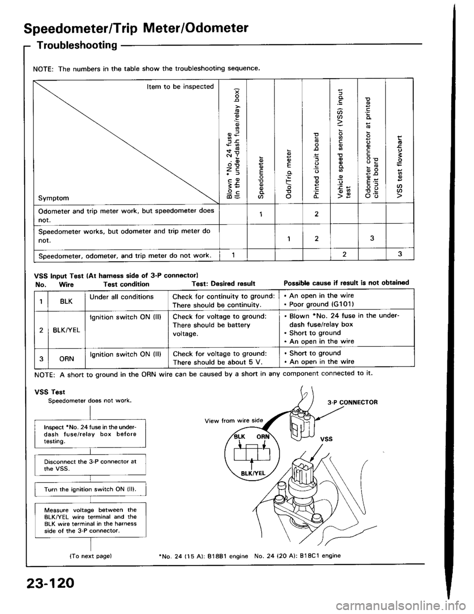
Speedometer/Trip Meter/Odometer
Troubleshooting
NOTE: The numbers in the table show the troubleshooting sequence.
Item to be inspected
Symptom
-9
;6+*c.r i.(D
zc*f
;59cd)=
E
a
6
E
'iF
o
(L
:lt)a
o
-9
>g
q)
qlv
E
'
E
oo
Odometer and trip meter wotk, but speedometer does
not.12
SDeedometer works, but odometer and trip meter do
nor,1
Speedometer. odometer, and trip meter do not work.
VSS Input Test (At ham€ss side of 3-P connector)
No. Wir6Tost conditionT€st: Desirsd resultPossible cause it result is not obtained
1BLKUnder all conditionsCheck for continuity to ground:
There should be continuity.
. An open in the wire. Poor ground (G1O1)
BLK/YEL
lgnition switch ON (ll)Check tor voltage to ground:
There should be battery
voltage.
Blown *No. 24 fuse in the unde.-
dash tus€/relay box
Short to ground
An open in the wire
ORNlgnition switch ON (ll)Check for voltage to ground:
There should be about 5 V.
. Shon to ground
. An open in the wire
NOTE: A short to ground in the
vSS Tost
Speedometer does not work.
ORN wire can be caused by a short in any component connected to lt.
3-P CONNECTOR
Inspect 'No. 24luse in the under-dash tuse/relay box beloretesting.
Turn the ignition switch ON lll).
Measure voltage between theBLK/YEL wire terminal and the8LK wire terminal in the harnessside of the 3-P connector.
{To next page)
23-120
24 (15 A): 81881 engine No. 24 {20 A): 818C1 engine
Page 1228 of 1413

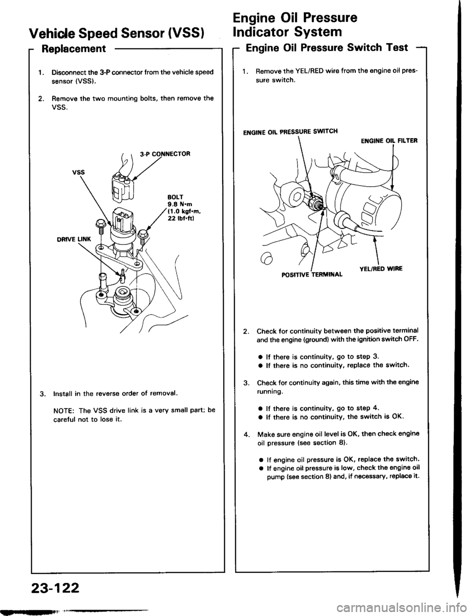
Replacement
Disconnect the 3-P connector trom the vehicle speed
sensor {VSS).
Remove ihe two mounting bolts, then remove the
VSS.
InstSll in the revsrse order of removal.
NOTE: The VSS drive link is a very small paru
caretul not to lose it.
Engine Oil Pressure
Vehide Speed Sensor (VSSIIndicator System
Engine Oil Pressure Switch Test
1. Remove the YEL/RED wile from the engine oil pres-
sure switch.
ENGI'{E OIL PRESSURE SWITCH
Check tor continuitv between the positive torminal
and the engine {gtound) with the ignhion swhch OFF.
a lf there is continuity, go to step 3.
a lf there is no continuity, replace the switch.
Check for continuity again, this time with th€ engine
runnrng.
a lf there is continuity, go to step 4,
a lf there is no continuity, the switch is OK.
Make sure engine oil level is OK, then check engin€
oil pressure (s€e section 8).
a lf engine oil pressure is OK, replace the switch'
a lf engine oil pressure is low, check the sngine oil
pump (see section 8) and, if necessary, replac€ it.
POSITIVE TERMII{AL
23-122
nlmlliitl