1994 HONDA INTEGRA check engine
[x] Cancel search: check enginePage 629 of 1413

lnspection and Adjustment
Pump Pressure Check
Check the fluid pressure as follows to determine
whether the trouble is in the pump or gearbox.
NOTE: First check the power steering fluid level and
pump belt tension,
CAUnON: Dilconn€st the high pros3uro ho3s with cale
!o e3 not to spill tho powor stooring fluid on th6 lramo
lnd olhor parG.
1. Disconnect the outlet hose from the oumo outlet fit-
ting, 8nd install the pump joint adapter on the
pump outlet.
2, Connect the hose joint sdapter to the power steer-
ing pressure gauge, then connect the outlet hose to
the adaotor.
3. Instsll the power steering pressure gauge to the
pump joint adaptor as shown.
OUTLET HOSE FlTnNG
HOSE ATTACHING BOLT1l Nm11.1 kg{ m 8lbf.ftl
6 x 1.0 m.n BOLT{P!rt of tooll11 N.m11.1 kgtm,8lbf.ftl
P/S JOINT ADAPTOR IPUMPIo?NAK - SmolrA
PUMP OUTI.TTFITIING
Open the shut-off valve fully.
Open the pressure control valve fully.
17 -22
1.
Start the engine and let it idle.
Turn the stee.ing wheel from lock-to-lock several
times to warm the fluid to operating temperature.
Measure steady-state fluid pressure while idling
with the shut-off valve fully open. lf the pump is in
good condition, the gauge should read less than
1500 kpa (15 kgf/cm,,213 psi).
lf it reads high, check the feed line or valve body
unit (see General Troubleshooting l7-10).
Close the shut-off valve. then close the pressure
control valve gradually until the pressure gauge
needle is stabl6, Read the pressure.
lmmediately open the shut-off valve fully.
CAUTION: Do not keep the shut-ott valvs closod
moro thgn 5 soconds or th9 pump could b6 dam"
agod by over-h6ating,
lf the pump is in good condition, the gauge should
read at least 6.400 - 7,400 kpa (65 - 75 kgIlcm,,924- 1,067 psi). A low reading means pump output is
too low for full assist. Repair or replace the pump.
10.
P/S PRESSURE GAUGE
Page 651 of 1413

Power Steering Pump
lnstallation
1.Connect the inlet and outlet hoses. Tighten the
pump fiftings securely.
Loosely install the pump in the pump bracket with
mounting bolts.
11N.m11.r kgf.m, 8lbf.ftlOUTIIT HOUSE
INI.TT HOSEO-RINGReplaco.
ADJUSTINGBOLT
PUMP MOUNTING BOLTS2,r N.m {2.4 kgl.m. 17 lbf'ft}
Install the DumD belt.
CAUTION:
. Make surs that thg powor gtooring bslt i!
securgly on the grooyos of ths pulloy!.
. Do not get powor stggring fluid o. groaso in thg
power steering bclt or pulley trc6. Cloan oft 8ny
tluid or groa36 belore installation.
POWER STEERING BELT
PULI..EY
5.
Adjust the pump belt (see page 17-201.
Fill the reservoir to the uoDer level line.
NOTE; Take care not to spill the fluid on the body
and parts. Wipe off the spilled fluid at once.
GAUTION: Uro only Ganuino Honda Powor Stsor.
ing Fluid-V. Using othor tlui& 3uch a3 ATF or oiher
manutacturor's powor steering tluid will drm89e
the rystgm.
SYSTEM CAPACITY:
1.06litor (1.12 US.qt, 0.93 lmp.qt)
RESERVOIR CAPACIW:
0.79 litor (0.1|:| US.qt, 0.?0 lmp.qtl
UP?ER I.fVEL LINE
IEVEI LINE
- Start the engine, let it run at idle, then turn the
steering wheel lock-to-lock severaltimes to bleed
air from the system.
- Recheck the fluid level and add some if neces-
s8ry.
CAUTIONT Do not fill tha .63ervoir boyond th6
upp€r lcvol lino.
17 -44
Page 1045 of 1413
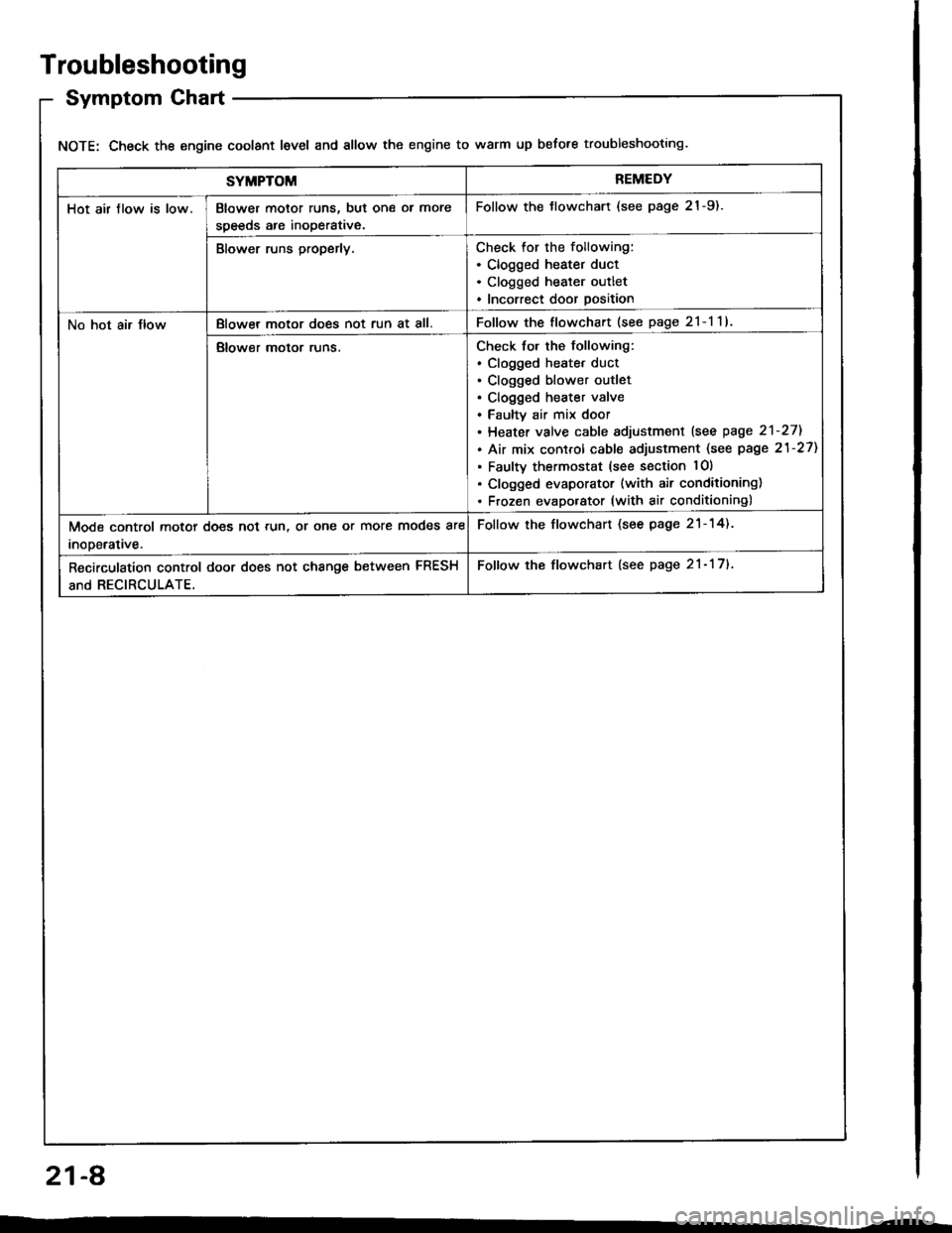
Troubleshooting
Symptom Chart
NOTE: Check the engine coolant level and allow the engine to warm up before troubleshooting.
SYMPTOMREMEDY
Hot air flow is low.Blower motor runs, but one ol more
speeds are inoperative.
Follow the tlowchart (see page 21-9).
Blower runs properly.Check for the following:. Clogged heater duct. Clogged heater outlet. Incorrect door position
No hot air JlowBlowel motor does not run at all.Follow the flowchart (see page 2l-l1l
Blower motor runs.Check for the following:. clogged heatet duct. Clogged blower outlet. Clogged heater valve. Faultv air mix door. Heater valve cable sdjustment lsee page 2'l-271
. Air mix control cable adjustment (see page 21-27)
. Faulty thermostat (see section lO)
. Clogged evaporator (with air conditioning). Frozen evaporator (with air conditioning)
Mode control motor does not run, or one or more modes are
inooerative.
Follow the flowchart (see page 21-14).
Recirculation control door does not change between FRESH
and RECIRCULATE.
Follow the flowchart (see page 21- 17).
21-A
Page 1075 of 1413
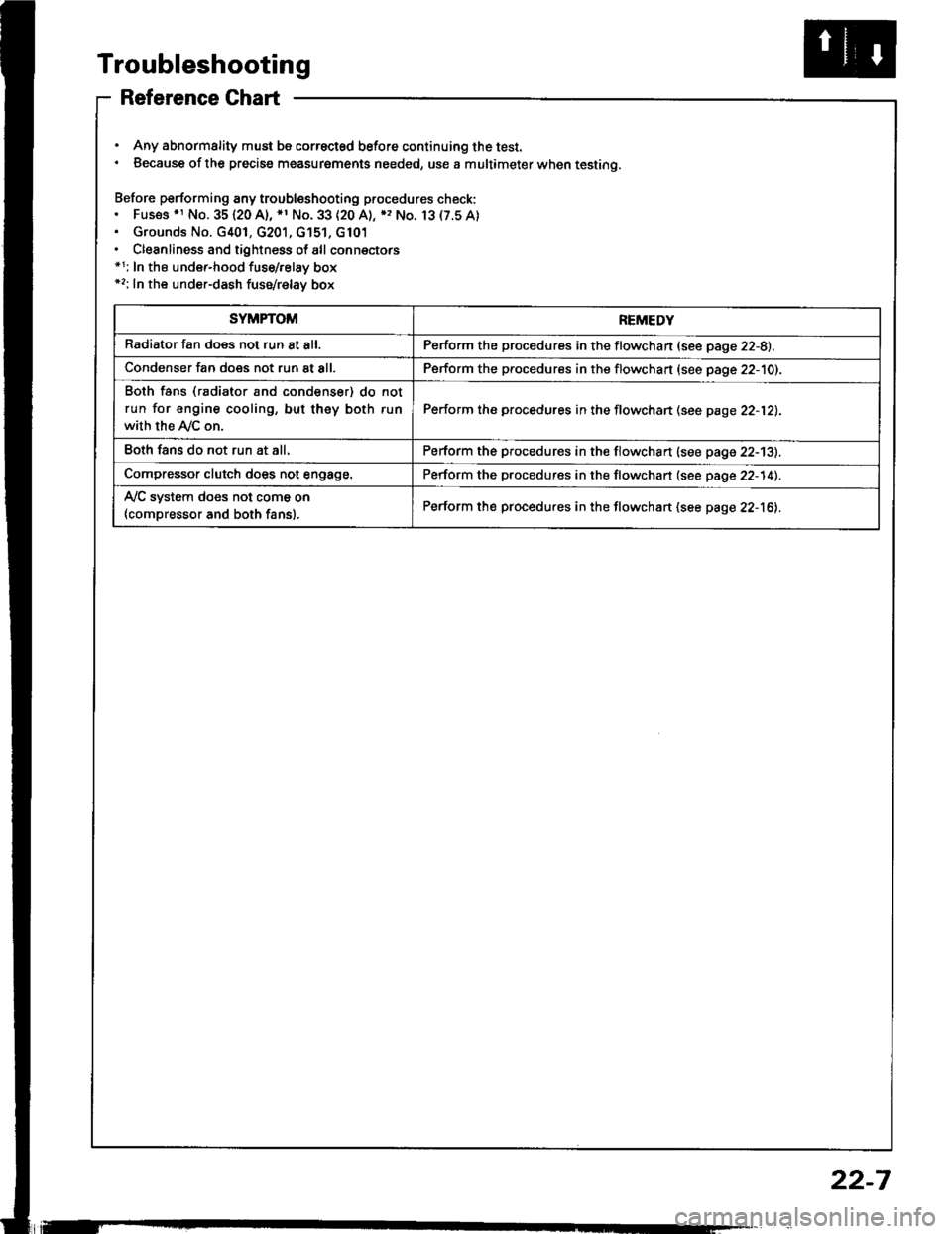
Troubleshooting
Reference Ghart
. Any abnormality must be correctsd before continuing the test.. Because of the precise measurgments needed, use a multimeter when testing.
Before performing any troubleshooting procedures check:. Fus€s .r No. 35120 A), *1 No. 33 (20 A), ), No. 13(7.5A). Grounds No. G401, G201, G'151, G101. Cleanliness and tightness of all connectors*1: In the under-hood fuse/relay box*2: In the under-dash fuse/relay box
SYMPTOMREMEDY
Radiator fan does not run 8t all.Perform the procedures in the flowchan (see page 22-8).
Condenser fan does not run at all.Perform the procedures in the flowchart (see page 22-10).
Both fans (radiator and condenser) do not
run for engine cooling, but they both run
with the Ay'C on.
Perform the procedures in the flowchan (see page 22-12).
Eoth fans do not run at all.Perform the procedures in the flowchart (see page 22-13).
Compressor clutch does not engage.Perform the procedures in the flowchart (see page 22-14).
Ay'C system does not come on
{compressor and both fans}.Perform the procedures in the flowchart (see page 22-16).
22-7
Page 1102 of 1413
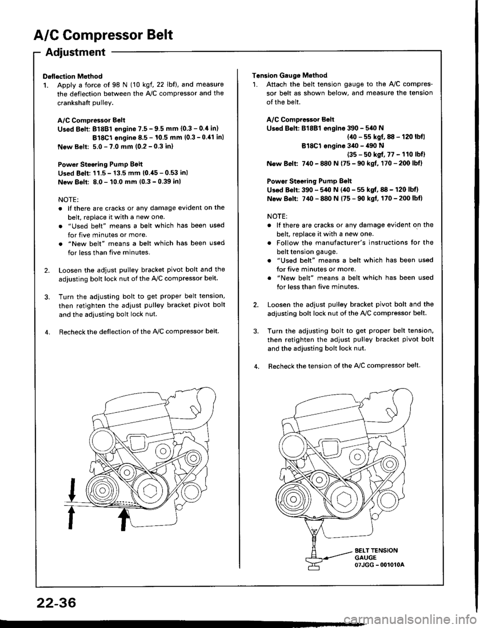
A/C Compressor Belt
Adjustment
Dstlsqtion Method
1. Apply a force of 98 N (10 kgf, 22 lbf), and measure
the deflection between the A,/C compressor and the
crankshaft Dullev.
A/C Compressor Belt
Us€d Eelt: 81881 engine 7.5 - 9.5 mm (0.3 - 0.4 in)
Bl8Cl engine 8.5 - 10.5 mm (0.3 -0.11 inl
New Belt: 5.0 - 7.0 mm (0.2 - 0.3 inl
Power Stesring Pump Belt
Used Beli: 'l1.5 - 13.5 mm (0.,[5 - 0.53 inl
New 8€lt: 8.0 - 10.0 mm (0 3 - 0.39 inl
NOTE:
. lf there are cracks or any damage evident on the
belt, replace it with a new one.
. "Used belt" means a belt which has been used
for five minutes or more.
. "New belt" means a belt which has been used
for less than five minutes.
2. Loosen the adjust pulley bracket pivot bolt and the
adjusting bolt lock nut of the Ay'C compressor belt.
3. Turn the adiusting bolt to get proper belt tension,
then retighten the adjust pulley bracket pivot bolt
and the adjusting bolt lock nut.
4. Recheck the deflection of the lvc compressor belt
22-36
Tonsion Gauge Method
1. Attach the belt tension gauge to the Ay'C compres-
sor belt as shown below, and measure the tension
of the belt.
A/C Compressot Belt
Used 8€lt: Bl8Bl engine 390 - 540 N
(40 - s5 kgf, 88 - 120 lbfl
Bl8Cl ongine 3il0 - il90 N
(35 - s0 kgf, 77 - 110 lbfl
N€w Belt 7,10 - 880 N {75 - 90 kgf, 170-200lbl}
Powor Steoring Pump Belt
Used Belt: 390 - 5,{l N (40 - 55 kgf, 88 - 120 lbll
N6w Bolt: 74O - 880 N 175 - 90 kgf, 170-200lbt)
NOTE:
. lf there are cracks or any damage evident on the
belt, replace it with a new one.
. Follow the manufacturer's instructions for the
belt tension gauge.
. "Used belt" means a belt which has been used
for five minutes or more.
. "New belt" means a belt which has been used
tor less than five minutes,
2. Loosen the adjust pulley bracket pivot bolt and the
adjusting bolt lock nut of the AVC compressor belt.
3, Turn the adjusting bolt to get proper belt tension,
then retighten the adjust pulley bracket pivot bolt
and the adjusting bolt lock nut.
4. Recheck the tension of the A{/C compressor belt.
Page 1109 of 1413
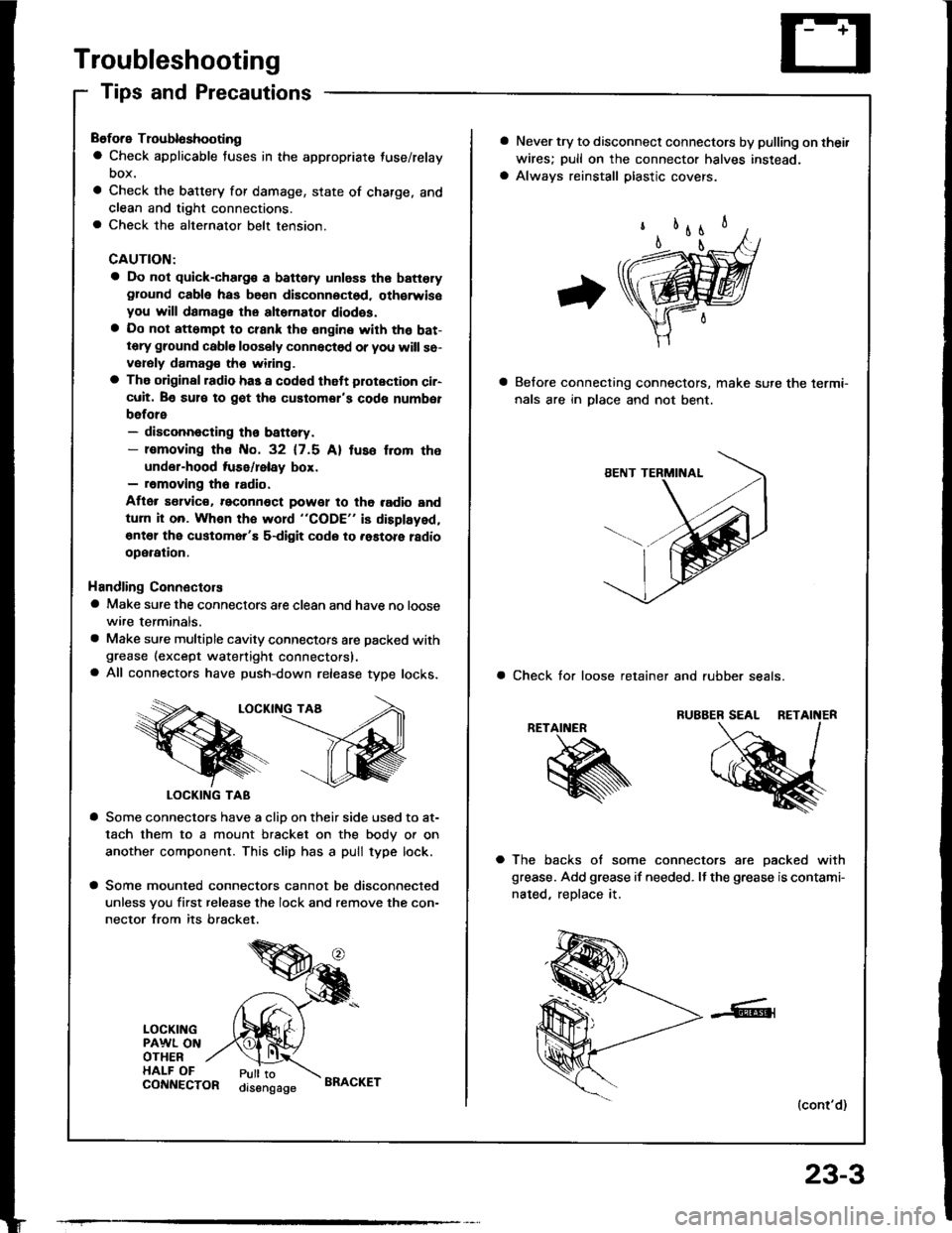
Troubleshooting
Tips and Precautions
Before Troubloshooting
a Check applicable fuses in the appropriate fuse/relay
DOX.
a Check the battery for damage, state of charge, and
clean and tight connections.a Check the alternator belt tension.
CAUTION:
a Do not quick-charg€ a battery unless the batteryground cabla has be€n disconnoctsd. oth€rwisoyou will damage the alternator diodss.a Do not att6mpt to crank the engine with the bat-tery ground cable loosely connectsd or you will se-vorsly damag€ tho widng.
a The original radio has a codod thatt plotection ci.-cuit. Be sul€ to got tho customor's code numbet
before- disconnecting th€ battery.- lomoving tho No. 32 (7.5 Al tuso f.om the
under-hood tuse/lelay box.- removing tho radio.
Aflor s€lvic€. reconn€ct powet to tho radio and
turn it on. Whon the word "CODE" is displayed,
€nt€l the customer'E s-digit codo to .astore ladio
operation.
Handling Connectors
a Make sure the connectors are clean and have no loose
wire terminals.
a Make sure multiple cavity connectots are packed withgrease (except watertight connectors).a All connectors have push-down release type locks.
LOCKII{G TAA
LOCKING TAB
a Some connectors have a clio on their side used to at-
tach them to a mount bracket on the body or on
another component. This clip has a pull type lock.
a Some mounted connectors cannot be disconnected
unless you first release the lock and remove the con-
nector from its bracket.
LOCKINGPAWL ONOTHERHALF OFPull toorsengageCONNECTORBRACKET
23-3
a Never try to disconnect connectors by pulling on thei.
wires; pull on the connector halves instead.
a Always reinstall plastic covers.
Belore connecting connectors, make sure the lermi-
nals are in Dlace and not bent.
a Check tor loose retainer and rubber seals.
RETAINER
a The backs of some connectors are oacked with
grease. Add grease if needed. It the grease is contami-
nated, reDlace it.
(cont'd)
Page 1182 of 1413
Starting System
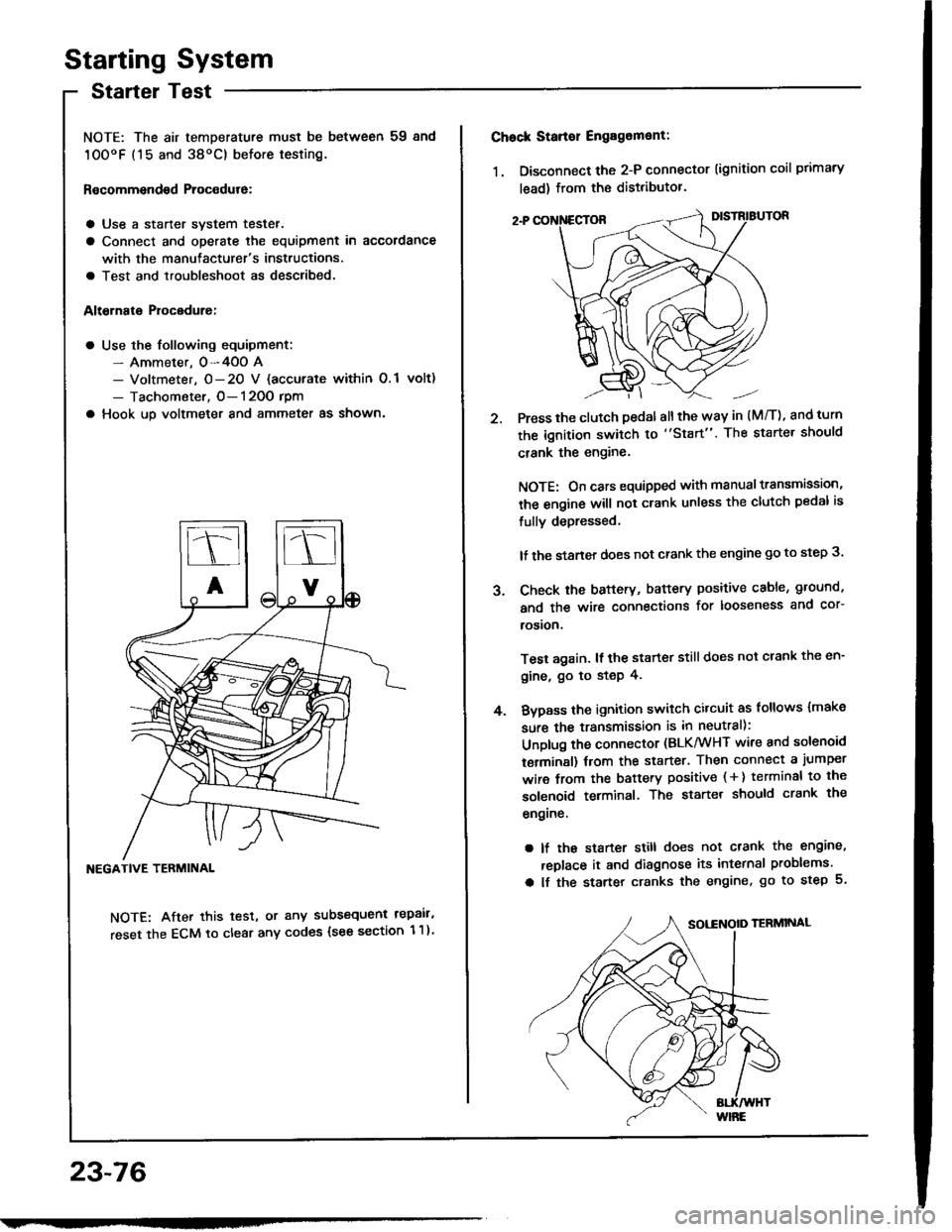
Startel Test
NOTE: The air temDerature must be between 59 8nd
10OoF (15 and 38oC) before testing.
Recommendsd Procodure:
a Use a staner svstem tester.
a Connect and operate the equipment in accordance
with the manutacturer's instructions.
a Test and troubleshoot as described.
Altohato Procedure:
a Use the following equipment:- Ammeter. 0-4OO A- Voltmeter, O- 20 V {accurate within 0.1 volt)
- Tachometer, O- 120O rpm
a Hook up voltmeter and ammeter as shown'
NEGATIVE TERMINAL
NOTE: After this test, or any subsequent repair,
reset the ECM to clear any codes (see section 1 1)
23-76
2.
Chock Stan€r Engag6ment:
1. Disconnect the 2-P connector (ignition coil primary
lead) from the distributor.
Press the clutch pedal allthe way in (M/T), and turn
the ignition switch to "Start". The starter should
crank the engine.
NOTE: On cars equipped with manual transmission,
the engine will not crank unless the clutch pedal is
fully depressed.
lf the staner does not crank the engine go to step 3.
Check the baftery, battery positive cable, ground,
and the wire connections for looseness and cor-
rosion,
Test again. lf the starter still does not crank the en-
gine, go to step 4.
Bvpass the ignition switch citcuit as follows {make
sure the transmission is in neutral):
Unplug the connector (BLK/WHT wire and solenoid
terminsl) trom the starter. Then connect a jumper
wire from the battery positive ( + ) terminal to the
solenoid terminal. The starter should crank the
engrne.
a lf the starter still does not crank the engine,
replace it and diagnose its internal problems.
a lf the starter cranks the engine, go to step 5.
J.
4.
Page 1183 of 1413
5. Check lor 8n op€n in the BLKMHT wire circuit be-
tween the staner and ignition switch, and con-
nectors.
6. Check the ignition switch (see page 23-70).
7, On cars with automatic transmission, check the A/Tgear position switch (neutral position switchl and
connector. On cars with manualtransmission, check
the staner cut relay, clutch interlock switch, and
connectors.
NOTE: Check the No. 39 (5O A) fuse in the under-hood
fuse/relay box for the starter cut relay.
Check tor Woar and Damago:
The starter should crank the engine smoothly and stead-
ily. lf th€ startsr engages, but cranks the engine errati-
cally, remove it. Inspect the starter, drive gear, and
flywheel ring gesr for damage.
a Check the drive gear overunning clutch for binding
or slipping when the armature is rotated with the drivegear held. Replace the gesrs if damaged.
Check Cranking Voltago 8nd Current Draw:
Cranking voltage should be no less than 8.O volts.
Current draw should be no more than 360 amperes.
lf cranking voltag€ is too low, or current draw too high,
check for:
a Fully charged battery
a Open circuit in starter armature commutatot segments
a Starter armature dragging
a Shoned armature winding
a Excessive drag in engine
Chack Cranking rpm:
Engine spsod during cranking should be above 1O0 rpm.
lf spe6d is too low, ch€ck for:
a Loose battsry or starter teminals
a Excessively worn starter brushes
a Open circuit in commutator segments
a Dirty or damaged helical spline or drive gear
a Defective drive gear overrunning clutch
Chock StErtor Disongagomoni:
Press the clutch pedal allth€ way in (M/T), turn the ioni-
tion switch to "lll" and rolease to "11".
The starter drive gear should disengage from the tlywheel
ring gear. When you rolease the key.
lf the drive gear hangs up on th€ flywheel ring gear, check
for:
a Solenoid plunger and switch malfunction
a Dirty drive gear assembly or damaged overrunning
clutch
23-77