Page 455 of 1413
{
oooooooooooo
ooooooooooooooooooooooo
oooooooooooMeasure the resistance betweenthe A5 and 425 or 426 terminals.
ls the resistance 14-16 0?
NO
3P CONNECTORView from terminal side.
SHIFT CONTROLSOLENOID VALVEASSEMBLY
(cont'd)
Chock lor loora TCM connectoE.lf n6c€53ary, sub3titut6 a known-good solonoid valvo assembly orTCM and r6check.
Disconnect the 3P connector tromthe shift control solenoid valve as-sembly.
Check for continuitv between theA5 and A25 or 426 torminals.
Ropair shon to ground in BLUI'ELwir6 botwoon tho A5 tstminal andtho shift conlrol solonoid valvo A.
Measure lhe resistance of thesolenoid at lhe 3P connector.
Check fo. opon in BLU/YEL wirobolween th6 A5 torminal and thoshift control solenoid valve A.
ls the resistance '14-16 0?
14-63
Page 456 of 1413

Electrical Troubleshooting
Troubleshooting Flowchart (cont'dl
Possible Cau6e
. Disconnected shift control sole-noid valve B connector. Short or open in shift controlsolenoid valve B wire. Faulty shilt control solenoidvalve B
Solfdiagnolir [!4 Indicato. lightbllnk! eight tim6r.
Turn the ignition switch ON.
Check whother the MalfunctionIndicator Lamp {MlL) blinks (seesection I 11.
Rcpsir rho FGM-FI Syrtem lso6scciion l1l.ls the MIL blinking?
Turn the ignition swirch OFF.
Oisconn€ct the 26P and 22P con-nectors trom the TCM.Connect the Test Harness "A"
and "D" connectors to the wirohamess only. not to the TCM {sesp6ge 14-49).
Turn the ignition switch ON.
Measure the voltage betwe€n theD18 and A25 or A26 terminals.
Ropeir opon or short in WHT/BLKwiro trotweon th6 D18 termineland tho EcM.
ls the voltage 4.75-5.25 V?
Measure the voltage between th€A3 and A25 or A26 terminals.
Ropair rhort to powor rourco inGR /WHT wir6 b€twgan tho A3tormirEl and shift conLol lolonoidvalve B.
Turn the ignition switch OFF.
A2s( - |
DlA( + I
o oooooooooo
ooooooooooooo oo ooo ooooo
oooo o o oo
To page
Page 457 of 1413
Measure the resistance betweenthe A3 and A25 or A26 terminals.
Chod. lor looro TCM connoctoB.lf nocdaary. 3ubatltute a known-good rolonold valv6 6ra6|nbly otTCM snd recheck.
ls the resistance I +16 07
Disconn€ct th6 3P conngctor fromthe shift control solenoid valveassembly.
Check for continuity between theA3 and A25 or A26 terminals.
Ropair short to ground in GRt{/WHT wiro botwoon th6 A3 tormi-nrl and tho shitt control aolonoidvalve B.
Measure the resistance ot thesolenoid at the 3P connector.
Chock to. open in GRN/WHT wirob6twe.n th€ A3 lerminal and thoshifl control solonoid valvo B.ls the r€sistance 14- 16 O?
oooooooooooo
oooooooooooo
ooooooooooo
ooooooooooo
Roplace lhe rhift control solenoidvalve arr€mblv.
SHIFT CONTROLSOLENOID VALVEASSEMELY
(cont'd)
14-65
Page 458 of 1413
Electrical Troubleshooting
Troubleshooting Flowchart {cont'dl
ls the countershaft speedsensor installed properly
2P CONNECTOR
COUNTERSHAFTSPEED SENSOR
Possible Cause
. Loose or faulty connection be-rween the TCM and car harness.. Disconnected countershaft speedsensor connector. Short or open in the counter-shatt speed sensor wire. Faulty counlershaft speed sensor
Self-diagnosis Lq! indicator lighrblinks nino timos.
Disconnect the 2P conneclor lromthe countershaft speed sensorconnector,
Measure the resistance ot theco!ntershaft speed sensor.
ls the resistance 4OO 600 0?
To page 14-67
14-66
Page 459 of 1413
Disconnoct the 22P connectortrom the TCM. Connecr tho T€stHarness "D" connector to thewhe harness onlv, not to the TCMlsee page '14-49).
Check for continuitv betweenbody ground and 017 terminaland D15 terminsl individually.
Rgpllr short in BLU/GRI{ otBLU|/EL wlro b€twgon Dl7 andDl5 torminsla and ths countar-rhaft apo€d sengor.
Reconnect the countershaftsDe00 sensor connector.
Msasure the rgsistance betweenD 1 7 and 015 terminals.
Rgpair looa6 ta.minsl or opon in8LU/GRN o. 8LU/YEL wiro bo-trvaon D'17 and D15 tormindgand tho count6rlhafl !p6gd!€ntor,
ls the r€sistance 4OO-600 07
Ch6ck for looaa TCM conn6cto..ll nocaslrry, aubrlitut6 a known-good TCM a.d .6ch.ck.
(cont'd)
4-67
Page 461 of 1413
Conneci the Test Hs.ngs6 "A"
and "O" connectors to thg TCM.
Start the engine and warm it upto normal ope.ating t€mpsratuG(the rsdiator fan comes on).
Measurgthe voltage between the05 and A25 or A26 terminals.
Rlplir opsn or rhort in BED/WHTwira botwaan tra D5 torr nC lndtha ECT lanaor.
ls the voltago less th6n lV?
Ch.ct tor loora TCM co.rmcror..It nocgallry, sublthuta a known-good TCM .nd rechrck.
14-69
Page 462 of 1413
Electrical Troubleshooting
Troubleshooting Flowchart (cont'd)
Possible Cause
. Disconnected ignition coil con-neclor. Short or open in ignition coil
. Faulty ignition coil
Solt-diagnosis lq.l indicstor lightblinks elovon tim6s.
Disconnect the 26P connectorIrom the TCM.
Turn the ignition switch ON.
Measure the voltage between theAg (BLU) and A25 (BRNiBLK) orA26 (BRN/BLK) terminals.
ls there baftery voltage?R6pai? opon or short in BLU wirolrotwqan lh. A9 torminll 6nd th.ignilion c!il.
Ch6ck lor loos6 TCM connactora.It nacosaary, substituto a known-good TCM and rochock.
NOTE: View from wire side.
14-70
Page 463 of 1413

Disconnect lhe 26Pand 22P con-nectors trom the TCMConnect the Test Hahess "A"
and "D" connectors to the wireharness only, not to th€ TCM {seepare'14-49).
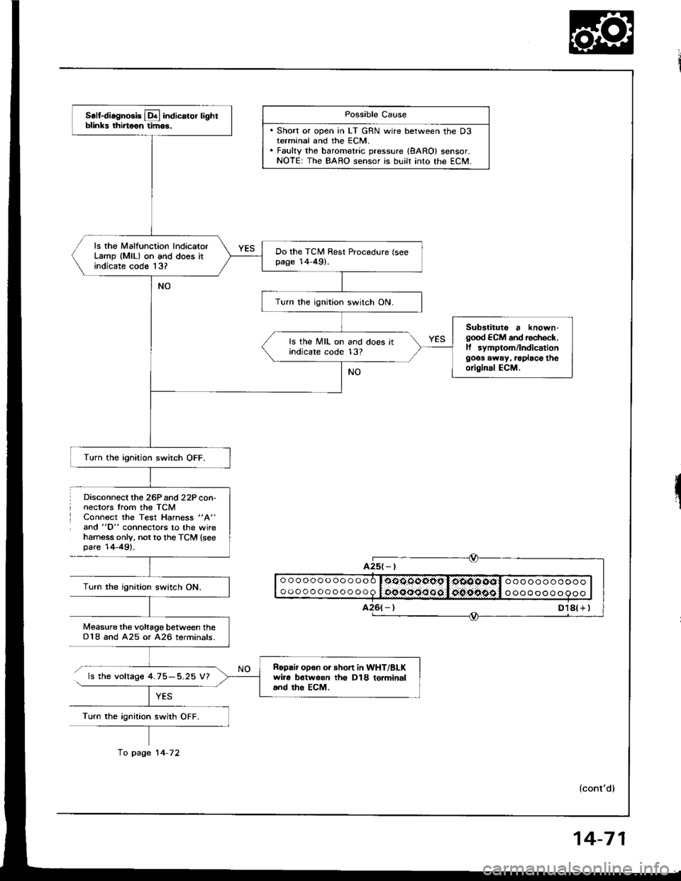
Possible Cause
. Short or open in LT GRN wire between the D3terminal and the ECM.. Fauky the barometric pressure {8ARO} sensor.NOTE: The BARO sensor is built into lhe ECM.
ooooooooooooo
oooooooooooo0oOOqgopg I,oiOOOOol ooo ooooooooooocqooo:Joo.oipggl o oooooo o 9ooTurn the ignition swirch ON.
Measure the voltage between theD18 and A25 or A26 terminals.
ls the voltage 4.75-5.25 V?
Turn the ignition swith OFF.
A25t- |
Soll-diagnosis Lq! indicator lightblinks thirtoon tim6.
ls rhe Malfunction lndicatorLamp (MlL) on and does itindicate code 13?
Do the TCM Rest Procedure (seepage 14-49).
Turn the ignition switch ON.
Substituto a known-good ECM and rechock.ll symptom/lndicationgoos away, .oplace theoriginal ECM.
ls the MIL on and does itindicare code 13?
Turn the ignition switch OFF.
Ropair opon or short in WHT/BLKwir6 botwoon th€ D18 to.minaland tho EcM.
fo page 14-72
14-71