Page 1312 of 1413
Rear Window Defogger
Component Location Index
CAUTION:
a All SRS olectrical wi ng ham€$6s are covoled with
y€llow insulation.
B6foro disconnocting any part of ths SRS wire har-
ness. connoct tho short connector(s).
Roplacs the ontire affectod SRS harness assombly if
it has an open circuit or damagcd wiring.
REAB WINDOWDEFOGGER RELAYTest, page 23-68
REAR WINDOWDEFOGGER SWITCHRemoval, page 23-209Test, page 23-2Og
REAR WINDOW DEFOGGERTest, page 23-210
UI{DER.DASH FUSE/RELAY BOX
REAR WINDOW DEFOGGER TIMER CIRCUIT
{ln the integrated control unil)fnput Test, page 23-147
SRS MAII{ HAR'{ESS
The rear window defogger is controlled by the integrated control unit, Pushing the defogger switch in the instrument
panel it sends a signal to the defogger time. in the integrated control unit, and the detogger stays on tor 25 minutes
or until the ignition switch is turned off. The indicator light in the switch comes on when the deJogger works.
23-206
Page 1314 of 1413
Rear Window Defogger
Troubleshooting
NOTE: The numbers in the table show the troubleshooting sequence.
'1: Hatchback'2: Sedan
Item to be inspected
Symptom
o
'
lD
*o--
o!
zi
ii9c
.E
o.-
:E
go
.E6
5.
o0to9\cg
o5('r6
z)
;5
o
!
ooooo
=3
oEDo
o
o
oo-
@=
g8
oo
o5
Defogger works, but indicator
light does not go on.1BLKTYEL oT BLU/YEL
Defogger does not work and
indicator light does not go on.122G201
G401YEL, BLUfYEL or BLK/YEL
Defogger does not work, but
indicstor light goes on.1423'1i G771',: G5O3
BLU|YEL or BLKIYEL
BLK/GRN oT BLKMHT
Defogger-on time is too long or
too short (normal operation time
is 25 minutes).
1
23-208
IINIilfi
Page 1315 of 1413
Switch Removal
CAUTION: Be caroful not to damags the hoator con-tlol/centel ail vent.
1, Carefully pry the switch out of the heater con-tfol/center air vent.
2. Disconnect the 6-P connecto, from the switch.
Remove the indicator bulb (turn the socket 45o
counterclockwise), and remove the illumination bulb.
REAR WINDOWDEFOGGER SWITCH
Switch Test
NOTE: Be caretul not to damage the heate. con-trol/center air vent.
1. Carefully pry the switch out of the heater con-
trol/center air vent.
2. Check tor continuity between the terminals acco.d-
ing to the table.
Torminal
P*il*__\IDF
PUSHEDo--oo-_o
o-
\../
-\-o
RETEASEDo-/\
o-
\:,,t
/:\\7
REAR WINDOW DEFOGGER SWITCH
[-4
I
) ll:g'", li'T
to.a4 wt
23-209
Page 1350 of 1413
+ No.24 ll5Al: 81881 onoineNo.24 l20Al: 818C1 ensine
UNDER-DASH FUSE/RELAY BOX
HORN
Y
UNOER _HOOD FUSE/RELAY BOX
No.4l (100A) No.39l50A)
INDICATORTIGHT{0,91W}
IP
I D Suur
6yffi Bi,G#,,'.
BTK
t-
G201G401
II
I
f7
VEHICLE SPEEDSENSOR iVSS)
M/r : CLUTCH SWITCH IA/T : A/T GEAR IPOS|T|oN SWTTCH IInIEI,E) I
PNK
BI-K
T
G201G401
Cruise Gontrol
Circuit Diagram
23-244
Page 1351 of 1413

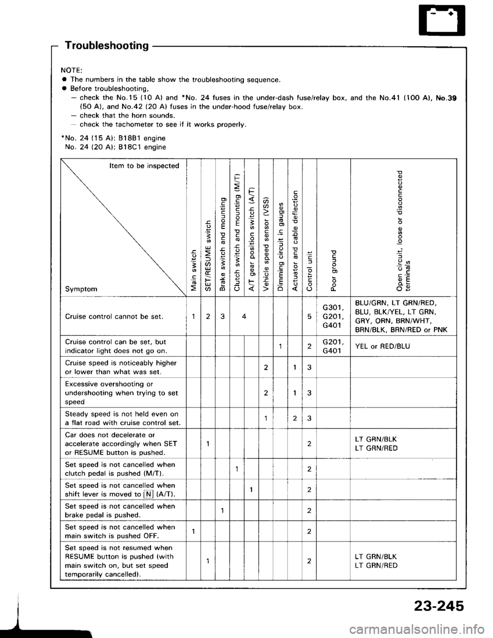
Troubleshooting
NOTE:
a The numbers in the table show the troubleshooting sequence.
a Before troubleshooting,- check the No.15 {10 A) and *No. 24 fuses in the under-dash fuse/relay box, and the No.41 (1OO A), No.39(50 A). and No.42 (20 Al fuses in the under-hood fuse/relav box.- check that the horn sounds.
check the tachometer to see if it wo.ks pfoperly.
*No. 24 {15 A): Bl8B1 engine
No. 24 {2O A}: 818C1 engine
Item to be inspected
Symptom
-c.
!I
.!o
;
U)
F
'Fcf
E
c
3
dl
F
o)
F
f
E
c
B
^
3
'.E
aa
_q
E
oi
.9:
E
.Eo
_9
l
If
L
!
.9
912'oE
og
Cruise control cannot be set.13
G301,
G201 ,
G401
BLU/GBN, LT GRN/RED.
BLU, BLK/YEL, LT GRN,
GRY, ORN. BRN/WHT,
BRN/BLK, BRN/RED or PNK
Cruise control can be set, but
indicator light does not go on.2G201,
G401YEL or RED/BLU
Cruise speed is noticeably higher
or lower than what was set.I3
Excessive overshootjng or
undershooting when trying to set
speed
2I
Steady speed is not held even on
a flat road with cruise control set.23
Car does not decelerate or
accelerate accordingly when SET
or RESUME button is pushed.
2LT GRN/BLK
LT GRN/RED
Set sDeed is not cancelled when
clutch Dedal is oushed (M/Tl.,1
Set sDeed is not cancelled when
shift lever is moved to fM tnnt.I2
Set speed is not cancelled when
brake pedal is pushed.'I2
Set speed is not cancelled when
main switch is pushed OFF.1
Set speed is not resumed when
RESUME button is pushed (with
main switch on, but set speed
temporarily cancelled).
LT GRN/BLK
LT GRN/RED
23-245
Page 1353 of 1413

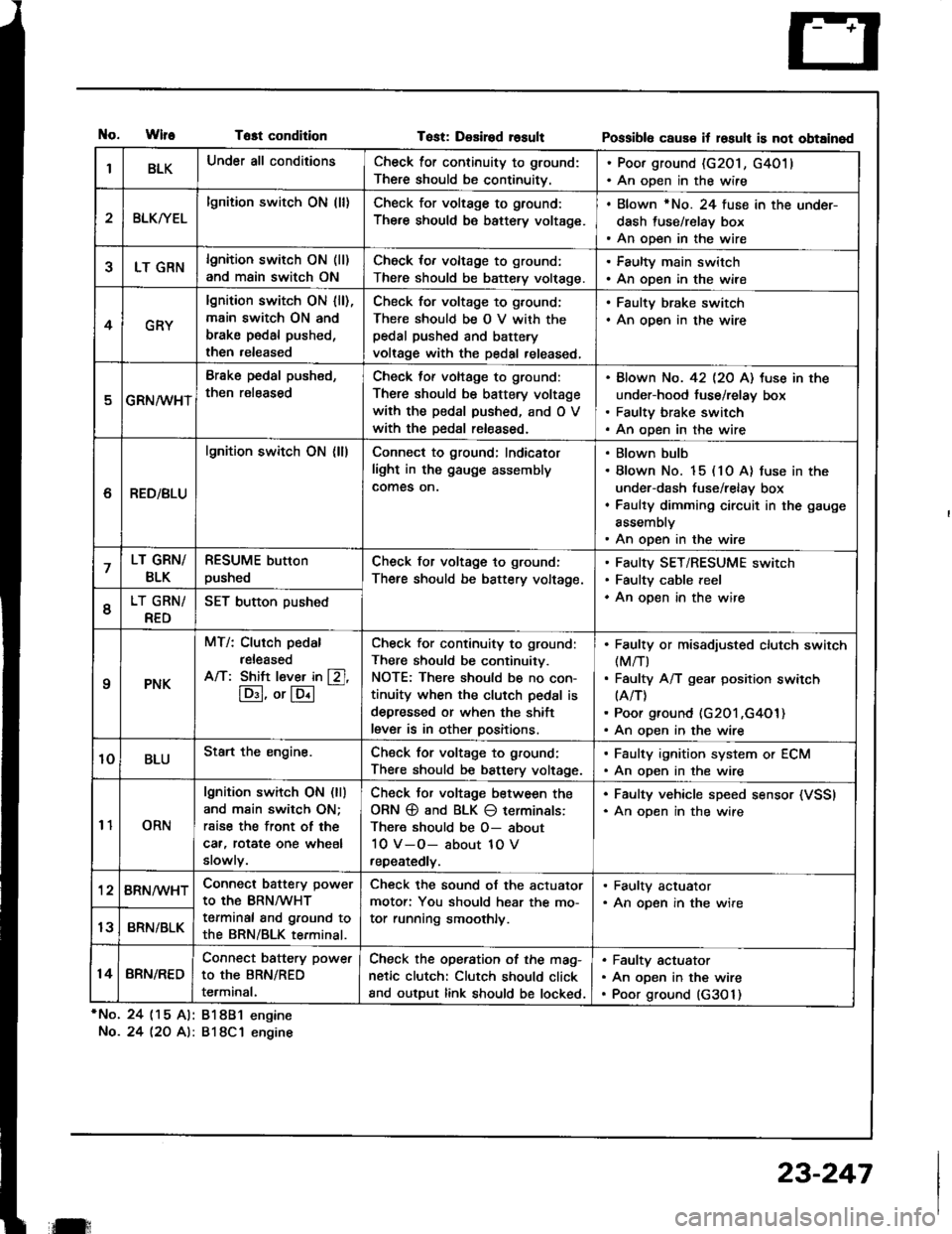
tlo.WlfeTost condition
*No. 24 (15 Al: 81881 engine
No.24 l2O A): 818C1 engine
Tost: Desired rosultPossibl6 caus€ it losult is not obtained
IBLKUnder all conditionsCheck for continuity to ground:
There should be continuitv.
. Poor ground (G201, G4011. An open in the wire
2BLKryEL
lgnition switch ON (ll)Check for voltage to ground:
There should be battery voltage.
. Blown rNo. 24 fuse in the under-
dash fuse/relay box. An open in the wire
5LT GRNlgnition switch ON (ll)
and main switch ON
Check for voltage to ground:
There should be battery volt€ge.
. Faulty main switch. An open in the wire
4GRY
lgnition switch ON lll),main switch ON and
brake pedal pushed,
then released
Check for voltage to g,ound;
There should be O V with thepedal pushed and battery
voltage with the pedal released,
. Faulty brake switch. An open in the wire
GRN/wHT
Brake pedal push€d,
then r€leased
Check tof voltage to ground:
There should be battery voltage
with the pedal pushed, and O V
with the Dedal released.
Blown No. 42 l2O Al tuse in the
under-hood fuse/relay box
Faulty brake switch
An open in the wire
6RED/BLU
lgnition switch ON (ll)Connect to ground; Indicator
light in the gauge assembly
comes on.
Blown bulb
Blown No. 15 (10 A) fuse in the
under-dash fuse/relay box
Faulty dimming circuit in the gauge
assembly
An open in the wire
7LT GRN/
BLK
RESUME button
pushedCheck for voltage to ground:
There should be battery voltage.
Faulty SET/RESUME switch
Faulty cable reel
An open in the wire6LT GRN/
RED
SET button pushed
qPNK
MT/: Clurch pedal
released
A/T: Shift l€ver in [Zl,
lD:I, or lE.l
-
Check for continuity to ground:
There should be continuity.
NOTE: There should be no con-
tinuity when the clutch pedal is
depressed or when the shift
lever is in other positions.
Faulty or misadiusted clutch switch(M/T)
Faulty A/T gear position switch(A/T)
Poor ground (G201 ,G4O1)An open in the wire
10BLUStart the engine.Chsck for voltage to ground:
There should be battery voltage.
. Faulty ignition system or ECM. An open in the wire
11ORN
lgnition switch ON (ll)
and main switch ON;
rsise the front of the
car, rotat€ one wheel
slowly.
Check Jor voltage between the
ORN @ and BLK O terminals:
There should be O- about
10 V-O- about 1O V
repeatedly.
. Faulty vehicle speed sensor (VSSI. An oDen in the wire
'128RN/WHTConnect battery power
to the BRN/WHT
terminal and ground to
the BRN/BLK terminal.
Check the sound of the actuator
motor: You should hear the mo-
tor running smoothly.
. Faulty actuator. An opsn in the wire
13BRN/BLK
14BRN/RED
Connect battery power
to the BRN/RED
terminal.
Check the operation of the mag-
netic clutch: Clutch should click
and output link should be locked.
Faulty actuator
An open in the wire
Poor ground (G3O 1)
il:
23-247
Page 1372 of 1413
Supplemental Restraint System (SRS)
Component Locirtion Index
UNDER.DASHFUSE/RELAY BOX
SRS INDICATOR LIGHT(ln th6 gaug6 assembly)Troubleshooting, page 23-276Gauge assembly, page 23-113
CABLE REELReplacement,page 23-301
AIRBAGBeplacement, page 23.295
SRS UNIT (lncluding cowl sensorl
SRS MAIN HARNESS-FRONT PASSENGER'S AIREAGBRANCH lExc€pt Caned. RS modol)
To CRUISE CONTROLSET/RESUME SWITCH
RIGHT DASH SENSORReplacement, page 23-305
FRONT PASSENGER'SAIRBAGlExcept Canads RS model)Replacement, page 23-295Disposal, page 23'299
LEFT DASH SENSORReplacement, page 23-305
23-266
Replacement, page 23-307
Page 1380 of 1413

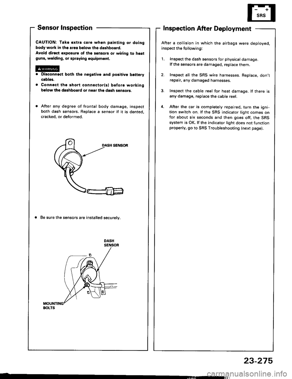
Sensor Inspection
CAUTION: Tak€ €xtra care whon painting or doing
body work in the ar€a bslow th6 dalhboard.
Avoid dirost exposure ot lh6 sonsors or wiring to hestguns, wolding, or spraying equipmont.
Di3connact both the nogativo and po3itivo b!ftery
cable3.
Connsct tho short conneclor(s) before working
bslow the da3hboard or nsar lhe dash sen3o.3.
After any degree of frontal body damage, inspect
both dash sensors. Replace a sensor if it is dented,
cracked, or deformed.
DASH SENSOR
a Be sure the sensors are installed securelv,
Inspection After Deployment
After a collision in which the airbags were deployed.
inspect the following:
1. Inspect the dash sensors for physical damage.
lf the sensors are damaged, replace them.
2. Inspect all the SRS wire harnesses, ReDlace, don'trepair, any damaged harnesses.
3. Inspect the cable reel for heat damage. lf there is
any damage. replace the cable reel.
4. After the car is completely repaired. turn the igni-tion switch on. lf the SRS indicator light comes onfor about six seconds and then goes off, the SRS
system is OK. lf the indicator light does not functionproperly, go to SRS Troubleshooting (next page).
BOLTS
23-275