1994 HONDA INTEGRA indicator
[x] Cancel search: indicatorPage 670 of 1413

lnstallation
CAUTION; BG Glrc{ul not io bcnd or drm8go tho piping
whcn in3tllling tho gea.box.
1. Before installing the gearbox, slide the rack all the
way to right.
2. Pass the right side of the steering gearbox above
and through the right side of the rear beam.
3. Hold the steering gearbox and slide the rack all the
wav to the left.
4. Raise the left side of the steering gearbox above
and through the left side of the rear beam.
5. Install the pinion shaft grommet and insert the pin-
ion shaft up through the bulkhead.
NOTE: Align the tab on the pinion shaft grommet
with the slot in the valve bodv.
6. Install and tighten the gearbox mounting bolts.
NOTE: After installing the gearbox, check the air
hose connactions for interference with adjacent
pans.
58 N.m 15.9 kg[.m, $ lbl.ftl
TAA
38 N m 13.9 kgl.m, 28 lbt.ftl
17-63
YELLOW GEAR TOOTH
7.Center the steering rack within its stroke.
Make sure that the cable reel of the SRS is centered
as follows:
. Turn the steering wheel left approx. 150 degrees,
to check the cable reel position with indicator.
. lfthe cable reel is centered. the yellow gear tooth
lines up with the alignment mark on the cover.
. Return the steering wheel right approx. 150
degrees to position the steering wheel in the
straight ahead position.
ALIGNMEi'IT MARK
Slip the lower end of the steering joint onto the pin-
ion shaft (line up the bolt hole with the groove
around the shaft), and tighten the lower bolt.
NOTE:
. Connect the steering shaft and pinion with the
cable reel and steering rack centered.
. Be sure that the lower steering ioint bolt is se-
curely in the groove in the steering gearbox pin-
ion.
. lf the steering wheel and rack are not centeted,
reposition the serralions at lower end of the
steering joint.
(cont'dl
22 N.m 12.2 kgi.m, 16lbf.ftlLOWER BOLT
Page 998 of 1413

3.Remove the rear console,
NOTE:
a Lift up the parking brake lever.
a Oetach the hooks by lifting the front ot the rear
console and sliding it rearward.
Remove the sshtrsy and front console panel.
> : Scrow locatlon3, 2
Diaconn€ct the connector.
4.
l
5. Remove the trim ring, then remov€ th€ consolepanel.
NOTE:
a Take cafe not to scratch the selecter l6ver 8ndA/T gear position indicator panel.
a Remove the shiJt lever knob (M/T).
A : Cllp, hook loc.tions
AA : Clip, 2 BA : Cllp, 2 CA : Hook, 2
SHIFT I.EVERKNOB
CONSOLE PANEL
IM/TI
TRIM RI'{G
"onroar€
,"Hr"t z{o$
co soLE
POStTtONSELECTERLEVEBINDICATOR PANEL
6. Remove the screws.
> : Screw locationr, 4
6bo'' I:./
20-129
Page 999 of 1413

Front and Rear Consoles
Replacement (cont'd)
7. Remove the Jront console as shown.
NOTE: Wrsp the selecter lever and A/T gear posi-
tion indicator psnel with a shop towel to prevent
damage.
20-130
8. It necessary, disassemble the Jront and rear
consoles.
: Scrow locations, 5
Ai
_Y_)
CONSOLE PANEL (M�TI
SHIFT LEVERBOOT (M/TI
: Scraw locations, I
AI
Y,/
REAR CONSOLE
PARKING BRAKECOVER
COVER SETPLATE
9. Installation is the reverse of the removal procedure.
CONSOLE
ARMREST
cof{solE Box
Page 1007 of 1413

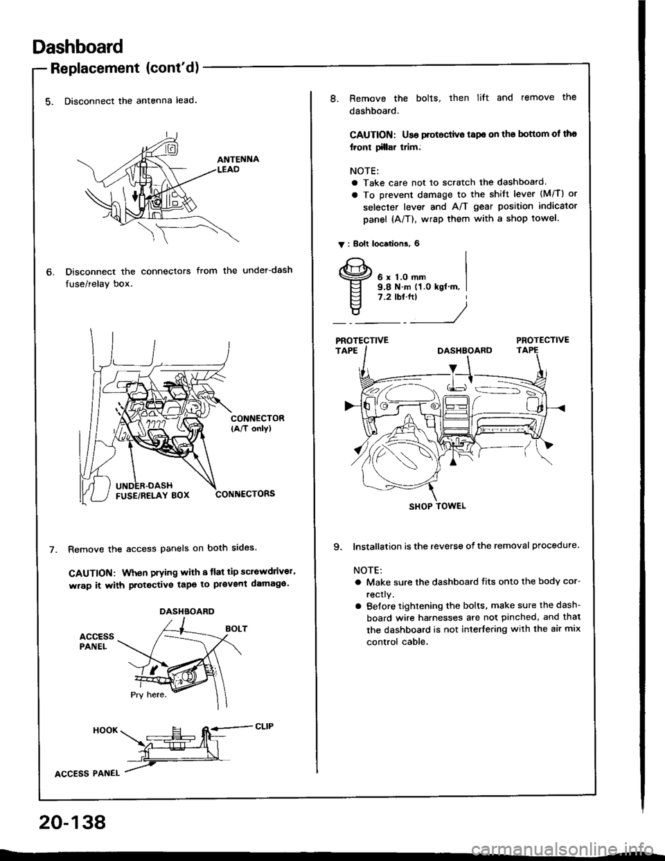
Dashboard
Replacement (cont'd)
5. Disconnect the antenna lead.
Disconnect the connectors
fuse/relay box.
from the under-dash
CONNECTOR(A/T only)
CONNECTORS
Remove the access panels on both sides.
GAUTION: When prying with 8 tlat tip scrowdrivor'
wrap it with protective tapo to pl€vent damaga'
accEssPANEL
6.
DASHBOARD
HooK ___E-- RE=-cLrP
ffiL
lcCesS Plnel /
20-138
8.Remove the bolts, then lift and remove the
dashboard.
CAUTION: Use protoctive tspe on the bottom ol tha
lront tillar trim;
NOTE:
a Take care not to scratch the dashboard.
a To prevent damage to the shift lever (M/T) or
selecter lever and A/T gear position indicator
panel (A/T), wrap them with a shop towel.
V : Bolt locations, 6
6 x 1.0 mm9.8 N.m (1.0 kgt'm, I7.2 tbt.ftt
____/
PROTECTIVE
9. lnstallation is the reverse of the removal procedure
NOTE:
a Make sure the dashboard fits onto the body cor-
rectly.
a Before tightening the bolts, make sure the dash-
board wire harnesses are not pinched, and thal
the dashboard is not interfering with the air mix
control cable.
SHOP TOWEL
Page 1107 of 1413

Electrical
Special Tools
Troubleshooting
Tips and Precautions ................................ 23-3Five-stop Tloubleshooting ..............,...-..-... Z3-sSchematic Symbols ................................_. 23-6wire Color Cod€s ..................................... 23-6Relay and Control Unit Locations
Engine Compartment .........,............ ... --. 23-7Dsshboard and Door ..,,......................... 23-gDashboard and Floor ............................. 23-t OOuaner Panel .....-.....23-12Connector ldentification and WireHarness Routing ........ 23-i 3
Index to Circuits and Systems
Airbag ............... ...-..-... 2g-26sAir Conditioning ....,.. Section 2lAltelnator ......_.............. 23-99Anti-lock Brake Systsm (ABS) Section 19Automatic Transmission Section 14Battery .............. .......... 23-66Chafging System ........... 23-98rCigalstte Lighter .....................-...-......-..-.. Z3-2O4Cfock ................. ..........23-197rcruise Controf .......--..-... 23-242Distributor .................... 23-87Fan Controls ................. 23-1ogFuel and Emissions ... Section 1i*Fuses
Under-dash Fuse/Relay Box ................... 23-48Undor-hood ABS Fuse/Retay Box ............ 23-51Under-hood Fuse/Relay Box,.................. 23-52rGauges
Engine Coolant Temperature {ECT)Gauge ................ ..23-126Fuef cauge ............... 2g-123'Gauge Assembly ....--.23-113Speedometer .....-...,,. 23-114Tachometer .....,.....-.. 23-114Ground Distribution ........ 23-60Heater ,,,........,.... ..... Section 2lrHorn ................. ........... 23-199*fgnition Switch ............. 23-70fgnition Syst6m .......-..-.. 23-A7lgnition Timing .............. 23-89Indicator Lights"A/T Gear Position .............. ................... 23-1 32B1ak6 System ...,..,..-.23-127Engine Oil Pressura .............................. _ 23-1 51Low Fuel ............ ......23-125Malfunction Indicator Lamp {MlL} ...,,. Section I l
tfnteglated Control Unit ...29-144*lnterlock System ...................................... 23-1 3gLights, Exteriol
Back-up Lights ........... 23-179Brake Lights .............. 23-t8ltDaytime Running Lights {Csnada} ........... 23-156Front Palking Lights ............................. 23-1 65Flont Side Marker Lights ....................... 23-165Front Turn Signal Lights ........................ 23-1 65*Hazard Warning Lights .........................- 2g-1A4Headlights ................. 23-t6tLicense Plate Lights .............................. 23-1 69Taillights(Harchback) .......... 23-166
{Sedan) .............. .. 23-167Lights. Inteliol
Cargo Area Light {Hatchback) ...... -.. -.. -... 23-177Ceifing Light ........-..-.23-175
Dash Lights Blightness Controt .............. 23-t70Glove Box Lighr ................................... 23-1 69Spotfighr ............ ....-.23-174Trunk Light (Sedanl ............... .............. - 23.-177*Lighting Sysrem .......-.-... 23-152:Moonroof ,,.,.......,..,,,,,.-.23-211PGM-FI Systom ........ S€crion 11Power Distribution .,.-..--..23-54Power Door Locks .............,,..................... 23-233Power Mirors ..,..,....-...- 23-216Power Relays ...........,..... 23-68Power Windows ............ 29-222*Rear Window Defogger ........,... ..........,..... - 23-20,6Reminder Systems
Key-in Remindel System ....,.............,.... 23-1 50Lights-on Reminder System ................... 23-l 5f*Maintenance Reminder system ..,,.... -.. - -. 23-.1 2gSeat Belt Reminder System ..................- 23-125*Side Markel/Turn Signal/Hazard
Ffasher System .,..,..-.23.-1A4Spark Pfugs .........-...-..... 23-97Starting System ....,,.....-. 23-73*Stereo Sound System ...,.......................,,.. 23-l gg
Supplemental Restraint System {SRS} ......... 23-265Vehicfe Speed Sensor {VSS) .............--..-.... 23-122*Wiper/Washer Systom ...............--.........-..- Zg-254
rRead SRS pi€cautions on Page 23-271 betore workingin these areas.
-+
Page 1172 of 1413

Battery
a Battory tluid (6lectrolyt€l contains sulturic acid. lt may cauaa aevere burns iI it gots on your skin or in youl oyos.
Woar protoctivo clothing and I fac€ shield,- ll aloctrolyt6 gots on youl skin or clothos, rimo it off with wator immediately,- lf eloclrolyto g6ts in your oyos, tlush it out by splashing wat6r in youl eyes for at least 15 minutes; call a physiclan
immediately,
a A battery gives off hydrogon gas, lf ignit6d. tha hydrogsn will orploda and could crack tho baflory cas6 and splattor
acid on you. Koep spa*s. flames, and cigarottos away from the baftery.
a Overcharging will raiso ths tempelature ot th€ electrolyte. This may force electrolyte to splay out of the battery venta.
Follow lhe chargor manutacturer's instluctions and chargo tho battory at a prop61 rate.
NOTE: The original radio has a coded theft protection circuit. lt service to the car requires any of the lollowing, be sure
to get the customer's code number before- disconnecting the battery.- removing No. 32 (7.5 Al fuse from the under-hood fuse/relay box- removing the radio,
After service, reconnect power to the radio and turn it on. When the word "CODE" is displayed, enter the customer's
s-digir code to restore radio operation,
Use either a JCI or Bear ARBST tester, and follow the manufacturer's procedures. It you don'r have one of these com-puterized testers, follow this conventional test procedure:
To get accurate results, the temperature ot the electrolyte must be between TOoF l21ool and IOOoF {38oCl.
lf the case is cracked or the posts are loose,
replace the battery.
lf the indicator shows low electrolvte, add
distilled water it oossible.
Test Load Cspacity (# 1)
. Apply 3OO amp losd fo. 15 seconds to remove
surJace charge.. Allow 15 seconds recovery period.. Apply test load (see Test Load Chartl.. Record voltage at the end of 15 seconds.
Voltage stays above 9.6
volts: The batterv is OK.
23-66
Page 1202 of 1413

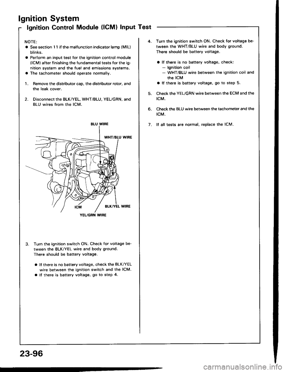
lgnition
lgnition
System
Control Module (lCMl Input Test
NOTE:
a See section I 1 if the malfunction indicator lamD (MlL)
blinks.
a Pertorm an input test for the ignition control module
(lCM) after finishing the fundamental tests for the ig-
nition system and the fuel and emissions systems.
a The tachometer should operate normally.
1. Remove the distributor cap, the distributor rotor, and
the leak cover.
2. Disconnect the BLK/YEL, WHT/BLU, YEL/GRN, and
BLU wires from the lCM.
3. Turn the ignition switch ON. Check for voltage be-
tween the BLK/YEL wire and body ground.
There should be battery voltage.
a lf there is no battery voltage, check the BLK^/EL
wire between the ignition switch and the lCM.
a lf there is battery voltage, go to step 4.
YEL/GRN wlRE
4.Turn the ignition switch ON. Check for voltage be-
tween the WHT/BLU wire and body ground.
There should be battery voltage.
a lf there is no battery voltage, check:- lgnition coil- WHT/BLU wire between the ignition coil and
the ICM
a lf there is battery voltage. go to step 5.
Check the YEL/GRN wire between the ECM and the
tcM.
Check the BLU wi.e between the tachometer and the
rcM.
It all tests are normal, replace the lCM.
6.
7.
23-96
Page 1206 of 1413

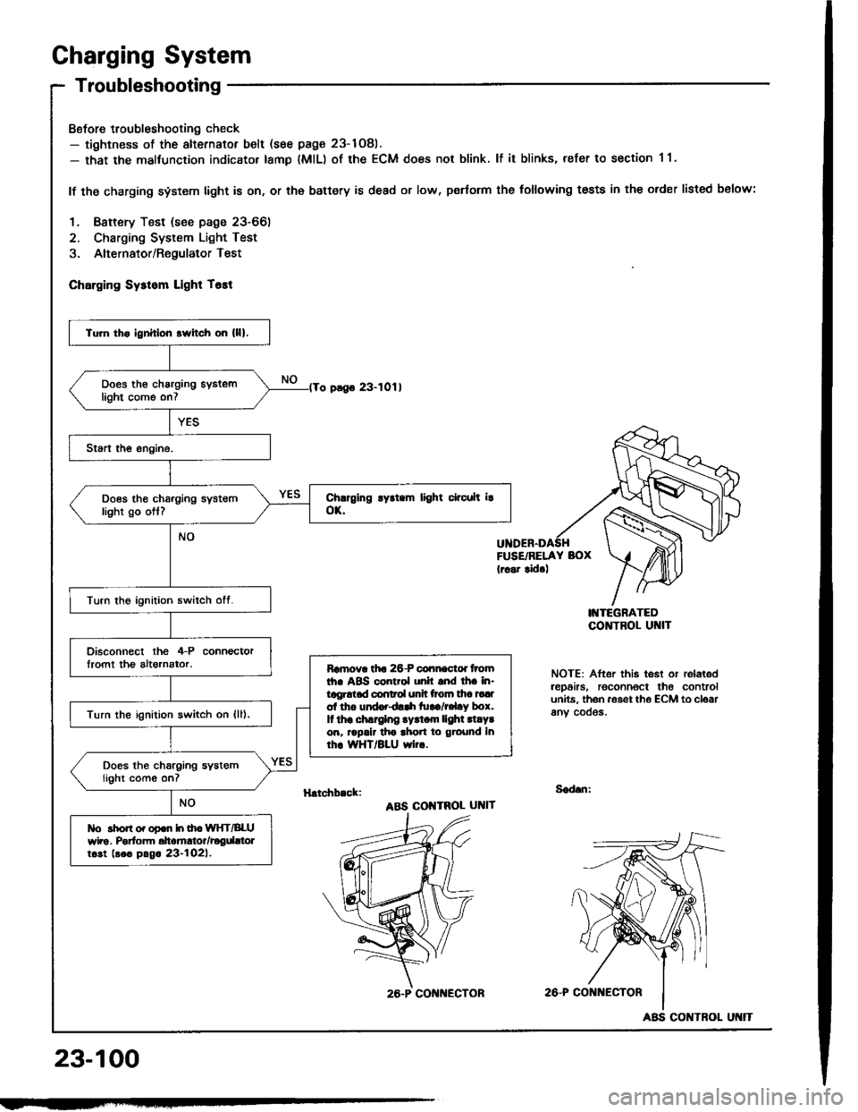
Charging System
Troubleshooting
Bofore troubleshooting check- tightness of the alternator belt (see page 23-1Og).- that the malfunction indicator tamp lMlL) of the ECM does not blink. lf it blinks, refer to section 1 1.
lf the charging system light is on, or th€ battery is dead or low, p€rtorm the following tests in the order listed below:
1. Baftery Test (see page 23-66)
2. Charging System Light Test
3. Alternator/RegulatorTest
ChErging Sysrom Light T6tt
o pago 23-1011
FUSE/RELAY BOX(r..r tid.)
I'{TEGRATEDCO]TTROL UI{IT
NOTE: After this test or relaledrep6irs, roconnoct the controlunits. th6n aoset th€ ECM to cloarany cooos.
H.tchb.ck:Sad.n:
ABS COI{TROL UNIT
2A-P CONi{ECTOR
23-100
Tu]n tho ignhlon srvitch on (lll.
Does th€ charging syslemlight come on7
Does tho charging systemlight go ott?
Turn the ignition switch otf.
Disconnect the 4-P connoctorlromt th€ altornator.Ramova tfto 26-P connactd tromth. ABS control unh snd lh. in-tggrotad conrol unh ttoln tha tadol tho und..dlrh tu!a/r.l.y box.It thr .hlrglng .yrtom lighl .l.Y.on, rrpalr tho ahon to ground Inrhr WHT/BLU wi...
Turn the ignition switch on {ll),
Does the charging systemlight come on?
tlo rhon o. opon h ih. WIfT/BLUwho. Porfom dtomrtor/rogdttolrost beo pag. 23-l02l.
26.P CON ECTOR
ABS CONTROL