1994 HONDA INTEGRA hose
[x] Cancel search: hosePage 1091 of 1413
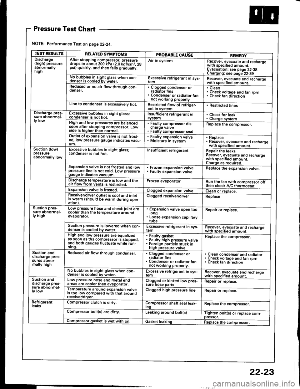
Pressure Test Chart
NOTE: Performance Test on page 22-24.
TEST RESULTSRELATED SYMPTOMSPROAABLE CAUSEREMEDYDischsrge(high) pressureabnormallynrgn
AftEr stopping compressor, pressuredrops to about 200 kPa (2.0 kof/cmr. 28psi) quickly, and then falls gr;dua y.
Air in systemRecover, evacuate and recharqowith sDecified amount. -
Evacuation: see Daqe 22-38Charoino: se6 D;op--2?-?qNo bubbles in sight g16ss when con-denser is cooled bv water.E-\cessive refrigerant in sys-Recover, evacuate and recharqewith specitied amount. -
Reduced or no air flow through con-oenser.Clogged condenser orradiato. finsCondenser o. radiator fannot working properly
CleanCheck voltage and fan rpmunecK lan ofeclton
Line to condenser is excessivelv hot.Restricted flow of refriger-ant In syslem. Restricted lines
Discharge pres-su re abnormal-Excossive bubbles in sight glass;condenser is not hot.Insuff icient refrigerant insyslemCheck for leakCharge systemHigh and low pressures are balancedsoon after stopping compressor. Lowside is higher than normal,
Faulty compressor dis-cnarge vaNsFaulty compressor seal
Replace the compressor.
Outlet of expansion vslve is not frost-ed, low pressure gauge indicates vacu-um,
. Faulty expansion valve. Moisture in sysiem. Replace. Recover, evacuate and recharoewith specified amount. -
Suction (lowlpressureabnormally low
Excessive bubbles in sight glass;conqenser rs not hot_Insuff icient ref rigerantReoair the leaks.Reaover, evacuate and recharoewith sDecifisd amount. -
Charqe as required.Expansion valve is not trosted and lowpressur€ line is not cold. Low pressuregauge Inorcates vacuum.
Frozen expansion valveFaulty expansion valveReplace the expansion valve.
Discharge temperaturg is low and theair flow from vents is restricted.Froren evaporatorRun the tan with comoressor oftthen check Ay'C thermostat.Expansion valve is frost€d.Clogged expansion valveCl€an or replace.Receiver/dryer outlet is cool and inletisrryarm (should be warm during oper-Clogged r€ceiver/dry€rReplace
Suction pres-su re abnormal-ly high
Low pressure hose and check joint arecooler than the temDeraturo aroundevaDorator.
'
ffin"nsion u"lu" oD"n too
. Loose expansion capillary
Repair or replace.
Suction pressure is lowered when con-denser is cooled by water,Excessive refrigerant in sys-remRecover, evacuate and recharqewith sDecifi€d amount. -
High and low pressure are equalizedas soon as the compressor is stopped,and both gauges fluctuate while run-nrng.
Faultv oasketFaulty Figh pressure valveForeign particle stuck inhigh pressure valve
Replace the compressor.
Suction anddischarg€ pres-sufes aonor-mally high
Reduced air flow through condenser.. Clogged condenser orradiator fins. Condenser or radiator fannot working properly.
Clean condenser and radiatorCheck voltage and fan rpmCheck fan direcrion
No bubbles in sight glass when con-cl€nser is cooled bv water.Excessive refrigerant in sys-remRgcover, €vacuate and recharoewith sp€cified amount.Suction snddischarge pres-su r€ abnormal-
Low pressure hose and metal endafeas are cooler than evaDorator.Clogged or kinked tow pre€-sure nos€ pansFepair or replace.
Temperature around expansion valveis too low compared with that aroundrecerver/orver.
Clogged high pressure lineRepair or replace.
Refrig€rantleaksCompressor clutch is dirty.Compressor shaft seal leak-IngReplace the comDressor.
Compressor bolt(s) are dirty.Leaking around bolt(s)Tighten bolt(sl or replace com-pressor.Compressor gasket is wet with oil. IGasket leakingReplace the compressor.
22-23
Page 1094 of 1413
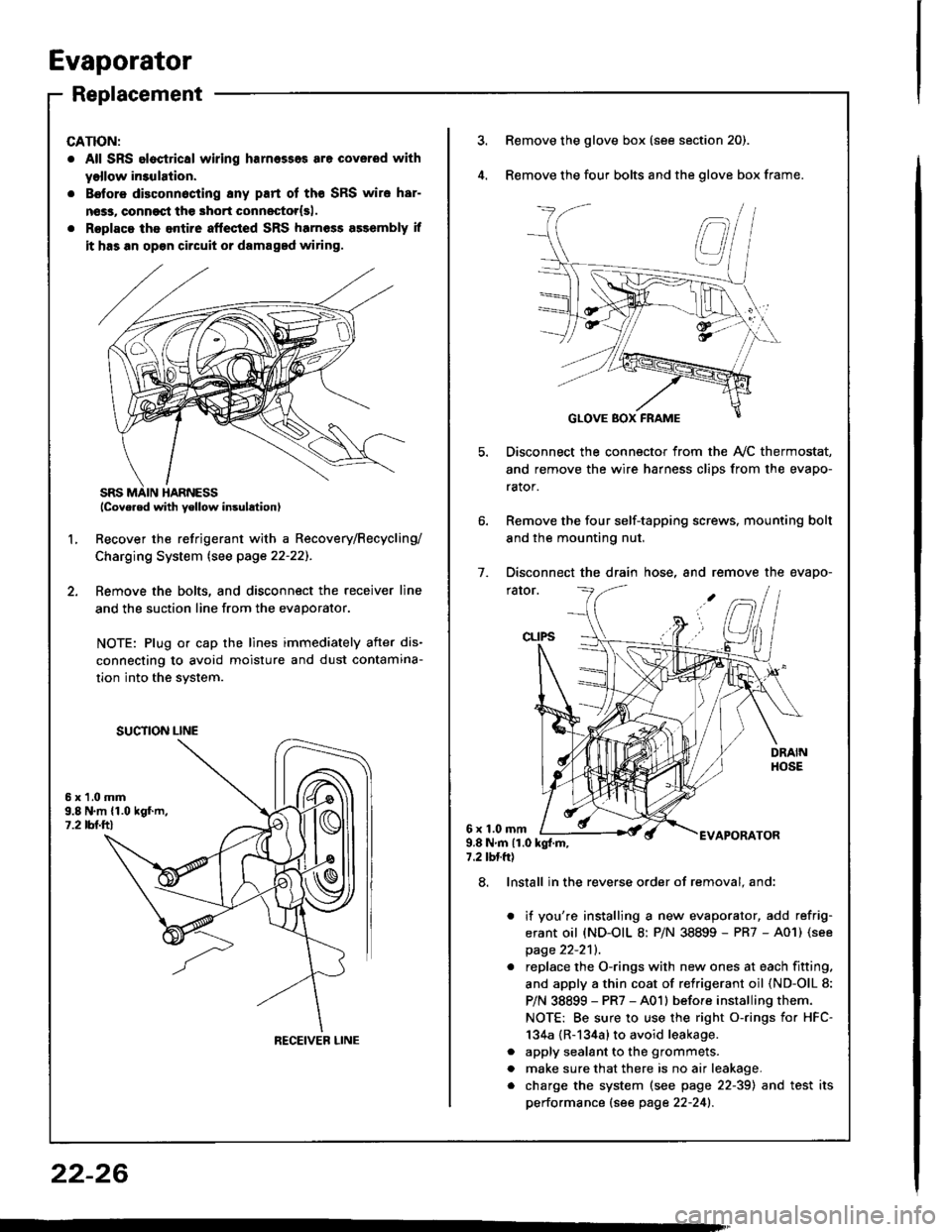
Evaporator
Replacement
CATION:
. All SRS eloctrical wiring harnesses are coverod with
yollow in3ulation.
. B€tore disconnocting 8ny part of tho SRS wire har-
nsss, conngqt th€ 3hort connestor{sl.
. Roplaca ths entire aftected SRS harness a$embly if
it has an op€n circuit or damaged wiring.
lcove.ed with yellow insulation)
Recover the refrigerant with a Recovery/Recycling/
Charging System lsee page 22-22]-.
Femove the bolts, and disconnect the receiver line
and the suction line from the evaporator.
NOTE: Plug or cap the lines immediately after dis-
connecting to avoid moisture and dust contamina-
tion into the svstem.
2.
L
6x1.0mm9.8 N.m {1.019f.m,1.2 tbl.ttl
SUCTION LINE
RECEIVEB LINE
3.Remove the glove box (see section 20).
Remove the four bolts and the glove box frame.
Disconnect the connector from the Ay'C thermostat,
and remove the wire harness clips from the evapo-
rator.
Remove the four self-tapping screws, mounting bolt
and the mounting nut.
Disconnect the drain hose, and remove the evapo-
rator.
1.
6x1.0mmAPORATOR9.8Nm{1.0kg{.m,7.2 tbtft)
a
a
8. Install in the reverse order of removal. and:
it you're installing a new evaporator, add refrig-
erant oil (ND-OIL 8: P/N 38899 - PR7 - A01) (see
page 22-2'll.
replace the O-rings with new ones at each fitting.
and apply a thin coat of refrigerant oil (ND-OlL 8:
P/N 38899 - PR7 - A01l before installing them.
NOTE: Be sure to use the right o-rings for HFC-
134a {R-134a} to avoid leakage.
apply sealant to the grommets.
make sure that there is no air leakage.
charge the system (see page 22-39) and test its
performance (see page 22-241.
22-26
Page 1103 of 1413
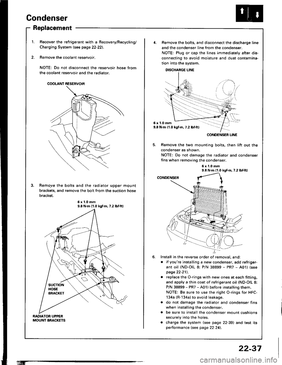
Condenser
Replacement
RAOIATOR UPPENMOUNT BRACKETS
Recover the relrigerant with a Becovery/Recycling/
Charging System (see page 22-221.
Remove the coolant reservoir,
NOTE: Do not disconnect the reservoir hose from
the coolant reservoir and the radiator.
COOLANT RESERVOIR
Remo.ve the bolts and the radiator upper mount
brackets, and remove the bolt from thg suction hose
bracket.
9.8 N.m {1.0 kgf.m.7.2 lbtftl
'1Iffi
22-37
6x1.0mm9.8 N.m (1.0 kgl.m,7.2 lbt.ft)
......-.....
CONOENSER LINE
Remove the bolts. and disconnect the discharge line
and the condenser line from the condenser.
NOTE: Plug or cap the lines immediately after dis-
connecting to avoid moisture and dust contamina-
tion into the system.
DISCHARGE LINE
Remove the two mounting bolts, then lift out the
condenser as shown.
NOTE: Do not damage the radiator and condenser
fins when removing the condenser.
6x1.0mm9.8 N.m (1.0 kgf.m, 7.2 lbl.tt)
Install in the reverse order of removal. and:
. if you're installing a new condenser, add refriger-
ant oil (ND-OIL 8: P/N 38899 - PR7 - A01) (see
page 22-21t,.
. replace the O-rings with new ones at each fitting,
and apply a thin coat of refrigerant oil {ND-OIL 8:
P/N 38899 - PR7 - A01) before installing them.
NOTE: Be sure to use the right O-rings for HFC-
134a (R-134a) to avoid leakage.
a do not damage the radiator and condenser fins
when installing the condenser,
. be sure to install the condenser mount cushions
securely into the holes.
. charge the system (see page 22-39) and test its
performance (see page 22 24!�.
Page 1110 of 1413
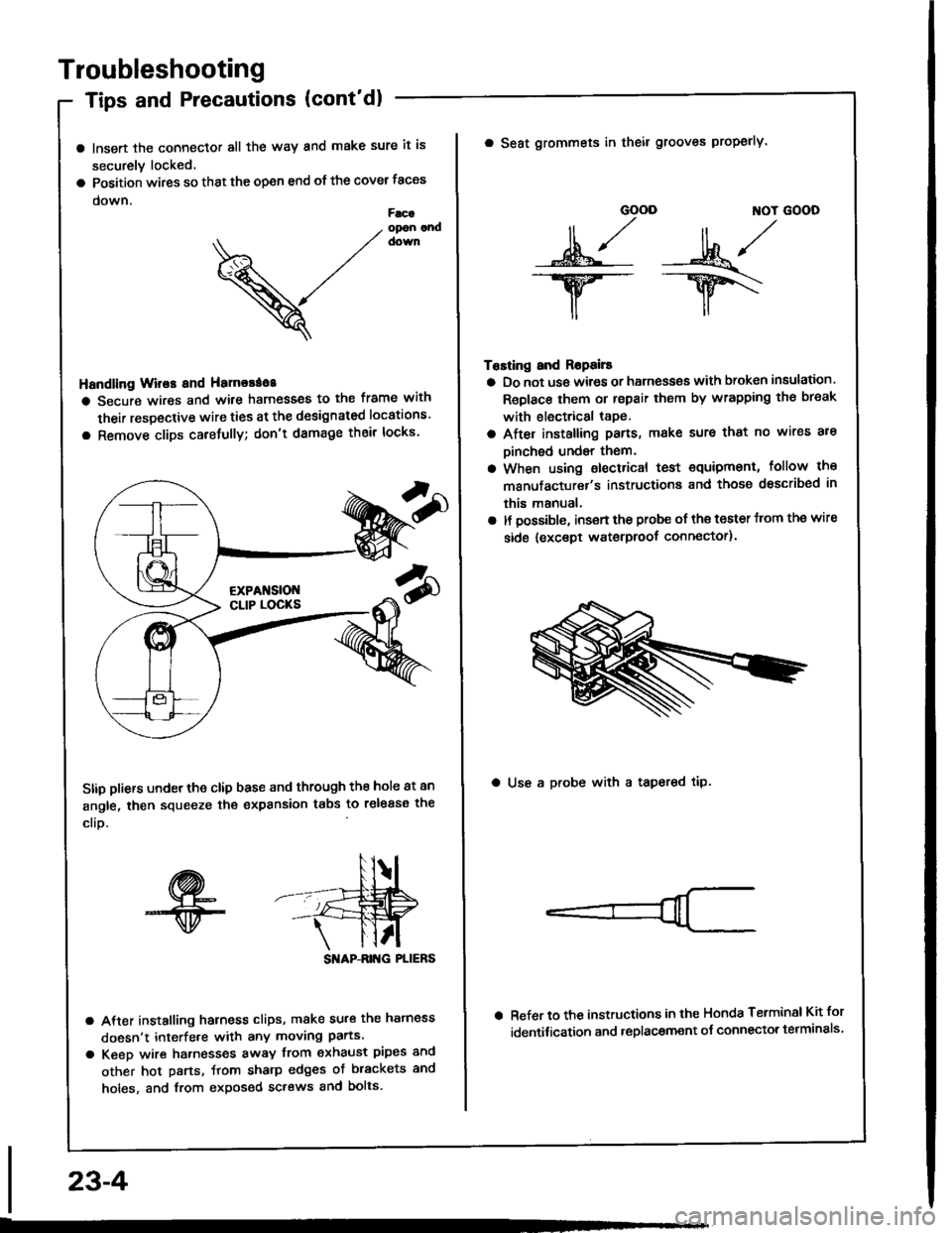
Troubleshooting
Tips and Precautions (cont'dl
a lnsert the connector all the way and make sure it is
securely locked.
a Position wires so that the open end of the cover taces
down.Facaopon andcown
V
Handling Wir€s and Hamorao8
a Secure wires and wile harnesses to the frame with
their respective wire ties at the designated locations'
a Remove clips carefully; don't damage their locks'
Stip pliers under the clip base and through the hole at an
angle, then squeeze the expansion tabs to release the
clio.
SI'IAP-ANG PLIERS
a After installing harness clips, make su.€ the hatness
doesn't interfe.e with any moving parts.
a Keeo wire hatnesses away from exhaust pipes and
other hot parts, ftom sharp edges of brackets and
holes, and from exposed screws and bolts.
23-4
GOOD ]TOT GOOD
n,/r/ll ,,' ll ,,
s*j -:ut*/-.w-- --ry\
il,,
Tosting and Ropails
a Do not us€ wires or harness€s with broken insulation.
Replace them or repair them by wrapping th€ break
with electrical tape.
a After installing pans, make sure that no wir€s are
Dinched undsr them.
a When using electrical test €quipment, follow the
manufacturer's instructiona and those dsscribed in
this manual,
a It possible, insert the probe of the toster from the wire
side {except waterproof connector).
a Seat grommets in theil grooves properly.
a Use a probe with a tapered tip.
Refer to the instructions in the Honda Terminsl Kit for
identification and .eplacement o{ connector telminals'
Page 1302 of 1413
Stereo Sound
Power Antenna
System
Motor Replacement
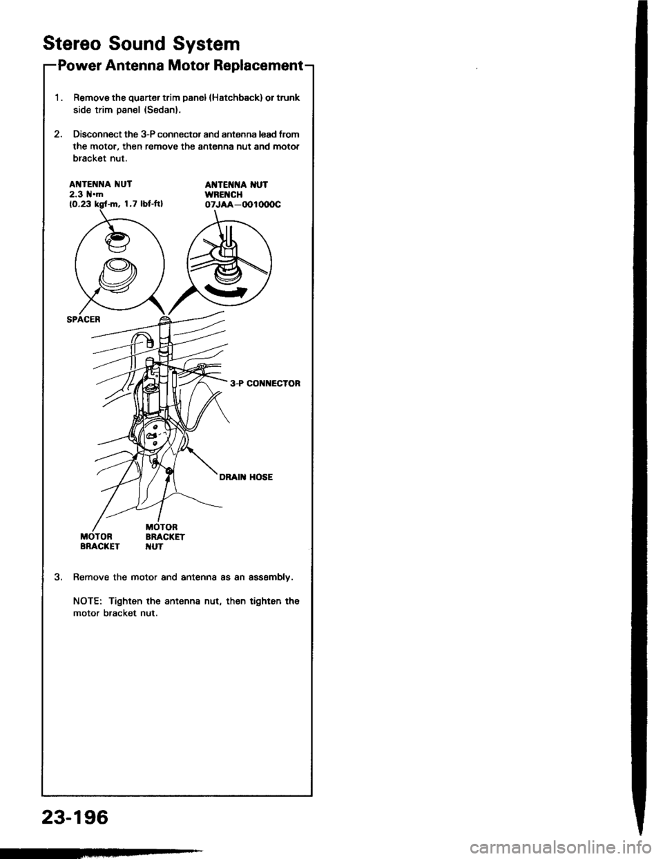
1.Remove tho quart€r trim panel (Hatchback) or trunk
side trim panel (Sedan).
Disconnect the 3-P connector and antenna lead trom
the motor, then remove the antenna nut and motor
bracket nut.
AI{TENNA 1{UT2.3 l{.mAT{TEI{]{A I{UTWBEI{CHoTJAA-OOlo(xrc
3+CO ECTOR
DRAI HOSE
MOTORBRACKETTUT
3.Remove the motor and antenna as an assemblv.
NOTE: Tighten the antenna nut, then tighten tha
motor bracket nut.
23-196
Page 1369 of 1413
l.
2.
1.
Rear Window Wiper Motor
Replacement
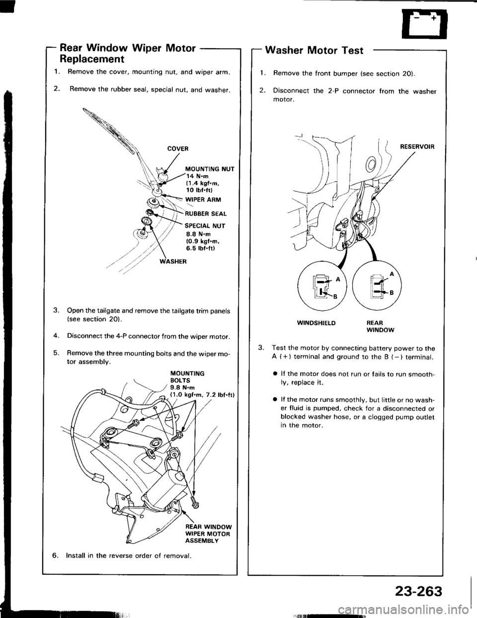
Remove the cover, mounting nut, and wiper arm.
Remove the rubber seal, special nut, and washer.
MOUNTING NUT
Washer Motor Test
Remove the front bumper (see section 20).
Disconnect the 2-P connector lrom the washer
motor.
RESERVOIR
WINDSHIELD
14 N.m11.4 kgf.m,10 tbt.trl
WIPER ARM
RUBBER SEAL
SPECIAL NUT
8.8 N.m{0.9 kgt'n,6.5 rbt.fr)
MOUNTINGBOLTS9.8 N.m(1.O kgf.m, 7.2 lbf.ttl
-4
)
Open the tailgate and remove the tailgate trim panels(see section 20).
Disconnect the 4-P connector from the wiper motor.
Remove the three mounting bolts and the wiper mo-
tor assembly.
REARwrNDow
Test the motor by connecting battery power to the
A ( + ) terminal and ground to the B (- ) terminal.
a ll the motor does not run or fails to run smooth-
ly, replace it.
a lf the motor runs smoothly, but little or no wash-
er fluid is pumped. check for a disconnected orblocked washer hose, or a clogged pump outlet
in the motor.
6, Install in the reverse order o{ removal.
23-263
Page 1370 of 1413
Wipers/Washers
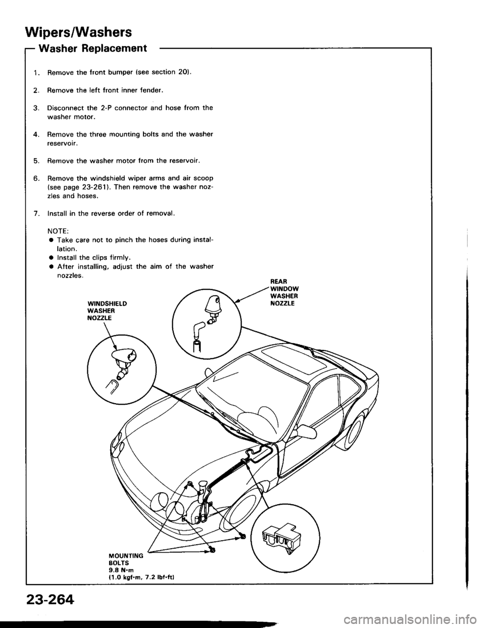
Washer Replacement
1.
5.
6.
Bemove the Jront bumper (see section 2Ol.
Remove the left lront inner fender.
Disconnect the 2-P connector and hose from the
washer motor.
Remove the three mounting bohs and the washer
reservorr.
Remove the washer motor from the reservoir.
Remove the windshield wiper arms and air scoop
(see page 23-261). Then remove the washer noz-
zles and hoses.
lnstall in the reverse order of removal.
NOTE:
a Take care not to pinch the hoses during instal-
lation.
a Install the clips tirmly.
a After installing, adjust the aim of the washer
nozztes.
7.
REARwtt{DowWASHERt{ozzLEWINDSHIELDWASHERNOZZLE
n
V..,.,,@
l(H
n
MOUNTINGBOLTS9.8 N.m{1.O kgf.m, 7.2 lbf.ftl
23-264