1994 HONDA INTEGRA hose
[x] Cancel search: hosePage 655 of 1413

Steering Gearbox
Disassembly
Stssring Rack Disassembly
NOTE:
. Before disassembling the gearbox, wash it off with
solvent and a brush.
. Do not dip seals and O-rings in solvent.
1. Remove the steering gearbox (see page 17-45).
2. Remove the air hose and clips.
3. Remove the tie-rod end and locknut.
4. Remove the boot bands and tube clamps. Pull the
boots away from the ends of the gearbox.
CLIP
BOOT
5. Hold the steering rack with a wrench and unscrew
the rack end with a wrench.
Loosen th6 locknut and remove tha rack guide
screw.
Ramove the spring and rack guide from the gear
housing.
7.
LOCKNUTRACK GUIDE
17-48,
TUBE CLAMP
Page 669 of 1413

Steering Gearbox
Reassembly (cont'dl
65. Adjust the air hose fitting position of the boots by
turning it as shown below.
Front
AIR HOSE FITTING
Connect the air hose between the right and left
boot. then install the clips on the cylinder pipe B assnown.
Install the right clipin this position.
CLIP
17-62
67.Install new boot bands on the boot and bend both
sets of locking tabs.
Lightly tap on the doubled-over portions to reduce
their height.
GAUTION: Stake tho band locking tabs firmly.
Slide the rack right and left to be certain that the
boots are not detormed or twisted.
Install the right and left tie-rod ends on the rack
ends.
70.
Page 670 of 1413

lnstallation
CAUTION; BG Glrc{ul not io bcnd or drm8go tho piping
whcn in3tllling tho gea.box.
1. Before installing the gearbox, slide the rack all the
way to right.
2. Pass the right side of the steering gearbox above
and through the right side of the rear beam.
3. Hold the steering gearbox and slide the rack all the
wav to the left.
4. Raise the left side of the steering gearbox above
and through the left side of the rear beam.
5. Install the pinion shaft grommet and insert the pin-
ion shaft up through the bulkhead.
NOTE: Align the tab on the pinion shaft grommet
with the slot in the valve bodv.
6. Install and tighten the gearbox mounting bolts.
NOTE: After installing the gearbox, check the air
hose connactions for interference with adjacent
pans.
58 N.m 15.9 kg[.m, $ lbl.ftl
TAA
38 N m 13.9 kgl.m, 28 lbt.ftl
17-63
YELLOW GEAR TOOTH
7.Center the steering rack within its stroke.
Make sure that the cable reel of the SRS is centered
as follows:
. Turn the steering wheel left approx. 150 degrees,
to check the cable reel position with indicator.
. lfthe cable reel is centered. the yellow gear tooth
lines up with the alignment mark on the cover.
. Return the steering wheel right approx. 150
degrees to position the steering wheel in the
straight ahead position.
ALIGNMEi'IT MARK
Slip the lower end of the steering joint onto the pin-
ion shaft (line up the bolt hole with the groove
around the shaft), and tighten the lower bolt.
NOTE:
. Connect the steering shaft and pinion with the
cable reel and steering rack centered.
. Be sure that the lower steering ioint bolt is se-
curely in the groove in the steering gearbox pin-
ion.
. lf the steering wheel and rack are not centeted,
reposition the serralions at lower end of the
steering joint.
(cont'dl
22 N.m 12.2 kgi.m, 16lbf.ftlLOWER BOLT
Page 671 of 1413

Steering Gearbox
Installation (cont'd)
10. Install the steering joint cover with the clamps andcliDs.
STEERING JOINT COVER
11. Connect the fluid lines to the valve bodv unit.
CLIP
RETURN HOSE
17-64
38 N.m 13.9 kg{.m, 28 lbf.ft)
12. Install the rear beam brace rod and return pipe
clamp on the rear beam.
NOTE: Install the rear beam brace toward thereturn pipe clamp.
13. Install the three way catalytic converter with thenew gaskets and new self-locking nuts, and connectthe heated oxygen sensor (H02S) connector,
HEATED OXYGEN SENSOR CONNECTOF
SELF.LOCKING NUT33 N.m 13.4
SELF.LOCKING NUT22 N.m (2.2 kgt m, 16 lbt.ftl
14. Connect the shift linkage (M/T model: see section
13, A/T model: see section 14).
Page 966 of 1413

Trunk Trim
Replacement
NOTE: Take care not to bend or scratch the panels.
'1. Fold the rear seat-back forwaro.
2. Lift the trunk mat, then remove the spare tire lid.
FASTENERS
3. Remove the clips, then remove the rear trim Danel.
V : Clip loc.tlorE
AV : Clip, 4- I l Push the inner clip.
NOTE: Do not push itin too Iar.
gV I Cllp, 2
- I I Loosen the inner clip.
TRUNK MAT
-2) Detach the clip by
pulling it.
Y_)
(8r-ct-tp
hfr
)J"'J..&G 4
eEdf,
II{NER
{* ,/
w
II{NEB CLIP
ffi
-21 Detach the clip by
pulling it.
@lqFl
-- t"
4. Remove the clips, then remove the trunk side panel
on each side.
NOTE: A clips on the trunk side panel can be re-moved in the same way as those on the rea. trimpaner.
< : Cllp locationt
A{ : Cllp, 68v : Cllp, 4
Installation is the reverse ot the removal procedure.
NOTE:
a lf necessary, replace any damaged clips.a When installing the rear trim panel, install the Aclip as follows.
- 1) Pull the inner clip up as shown.
tF tNt{ER
rd[h cLrP
H
v
-2) Install the clip in rhe rear trim panel, rhenpush the inner clip until it,s flush.
INI{ER CLIP
5.
20-97
Page 1059 of 1413

Heater Unit
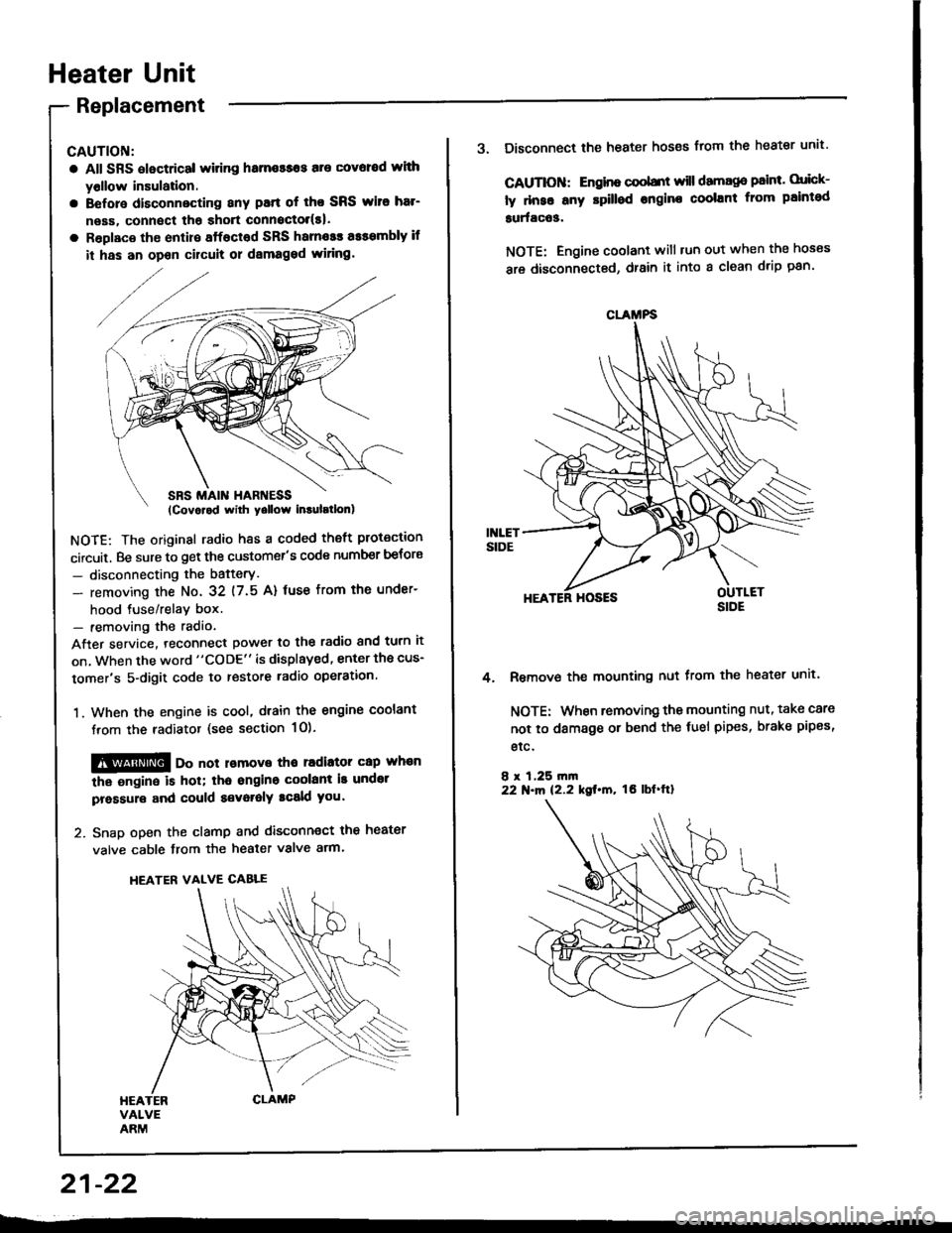
Replacement
CAUTION:
a All SRS electrical witing hame$os are covoed wlth
yollow insulation.
a Before disconnecting any patt of tho SRS wito har-
neas, connect tha shott connoctol(s|.
a Roplaco th€ enlire sffacted SRS harnosr a$smbly if
it has an opon cilcult or dsmaged wiring.
NOTE: The original radio h8s a coded theft protection
circuit. Be sure to get the customer's code number betors
- disconnecting the bafterY.
- removing the No. 32 (7.5 A) fuse from th€ under-
hood tuse/relav box.- removing the radio
After service. teconnect power to the radio and turn it
on, when the word "CODE" is displayed, enter the cus-
tomer's 5-digit code to restore radio operation.
1. When the engine is cool, dtain the engine coolant
from the radiator (see section 1O).
@@ oo not lomove tho radiator cap whan
the ongine is hol; tha ongino coolant is undot
pressure and could a€voralY tcald you.
2. Snap open the clamp and disconnect the heater
valve cable from the heater valve arm.
HEATER VALVE CABLE
21-22
CLAMFS
3. Disconnect the heater hoses from the heater unit'
CAUTIOII: Engino coobnt will damago paint. orick-
ly dnse any rpilled engine coolant from paintod
surfac63.
NOTE: Engine coolant will tun out when the hoses
are disconnected, drain it into a clean drip pan'
HEATER HOSES
Remove the mounting nut from the heater unit.
NOTE: When removing the mounting nut, take care
not to damage or bend the fuel pipes, brake pipes,
etc.
8 r 1,25 rn|n22 N.m 12.2 kgt.m, tO lbf'ftl
4.
Page 1060 of 1413

5.
6.
7.
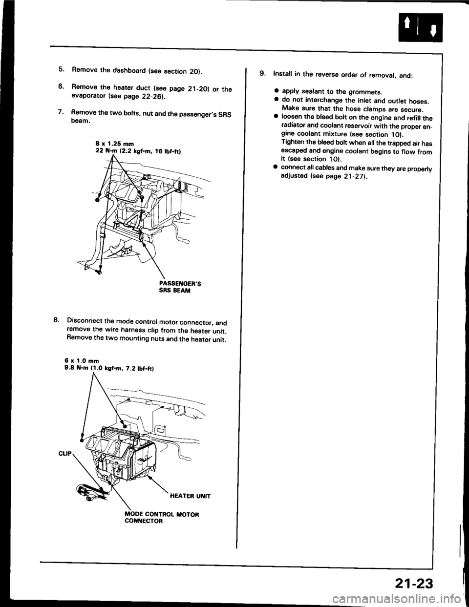
Rsmove the dashboard (see section 2O).
Remove the heater duct (see page 21-20) or theevaporator lse€ page 22-26).
Rsmove the two bolts, nut and the passenger,s SRS(}eam.
PASSEIVGER'SSRS EEAM
Disconnect the mode control motor conngctor, andremove the wire harness clip from the h€8ter unit.Remove the two mounting nuts and the haater unit.
6 r 1.0 mm9.8 .m (l.O kgt.m, 7.2 tbt.frl
MODE COI{TROL I,IOTORcol{t{€cToF
8.
8 x 1,26 mln22 N.m 12.2 kgf.m, 18 tbt.ttl
9. Install in the reverse order of removal, and:
a apply sealant to the grommets.a do not int6rchange the inlet and outl€t hoses.Make sure that the hose clamps are secure.a loosen th€ ble6d bolt on th6 engine and r€fillthetadiator and coolant r€servoir with the propsr en_gine coolant mixture (sse section 1O).Tighten the blsed boh when all the trapped air has6sc8p6d and engine coolant begins to flow fromit (see section 1O).a connect all csbles and make sure they 8re properlyadiusted (see pdge 21-271.
21-23
Page 1089 of 1413

A/C Service Tips and Precautions
The air conditioner system uses HFC-134a (R-134a) .efrigerant and polyalkyleneglycol (PAG) retrigerant oil (ND-OIL g: p/N
38899 - PR7 - A0l ), which are not compatible with CFC-12 \R-'12) refrigerant and mineral oil. Do not use R-12 refrigerant ormineral oil in this system, and do not attempt to use R-'12 servicing equipment; damage to the air conditioner system oryour servicing equipment will result.
only use service equipment that is u.L,-listed and is certified to meet the requirements of sAE J2210 to remove R-134afrom the air conditioner svstem.
CAUTION: Exposure lo air conditioner refrigorant and lubricanl vapor or mi3t cln irritato gyos, nose and throat. Avoidbreathing lhe air conditioner refrigerant and lubricant vapor or mist.
lf accidental system discharge occurs, ventilate work area befor€ resuming service.R-134a service equipment or vehicle air conditioner systems should not be pressure tested or leak tested with compressedair.
@ some mirtures of air and R-l3ifa have been 3hown to be combu3tible at slsvated prossuros and can relultin fire or explosion causing inlury or property damage. Never use complessod ai. to prgssure t€|st R-134a service equip-ment or vehicle air conditiongr systems.
Additional health and safety information may be obtained from the refrigerant and lubricant manufacturers.'1. Always disconnect the negative cable from the battery whenever replacing air conditioning pans.
2. Keep moisture and dust out of the system. When disconnecting any lines, plug or cap the fittings immediately; don'tremove the caps or plugs until just before you reconnect each line.
3. Before con necting a ny hose or line, apply a few drops of refrigerant oil (ND-OIL 8: P/N 38899 - PR7 - AO1) to the O-ring.4. When tightening or loosening a fitting, use a second wrench to support the matching fitting.5. When recovering the system, use a R-134a refrigerant Recovery/Recycling/Charging System; don't release refrigerantinto the atmosDhere.
6. Add refrigerant oil (ND-OlL 8: P/N 38899 - PR7 - A01) after replacing the following parts:
NOTE:
. To avoid contamination, do not return the oil to the container once dispensed, and never mix it with other refriqer-ant orls.
. lmmediately after using the oil, replace the cap on the container and seal ittoavoid moisture absorption,. Do not spill the refrigerant oil on the car; it may damage the paint; if the re{rigerant oil contacts the paint, wash itoff immediately.
Condenser ..................... 25 m/ (5/6 fl.oz, 0.9 lmp.oz)
Evaporator ................. ilo mf 17 113fl.oz,1.4 lmp.oz)
Line or hose 10 ml (1/3 fl.oz. o.il lmp'ozl
Receiver/Dryer .....,.,,...., 10 m{ l1l3 tl.oz, 0.4 lmp.ozl
Leakage repair .............. 25 mf (5/6 fl.oz, 0.9 lmp.ozl
Compressor For compressor .eplaco-
m€nt, subtract the volumo of oil drained from tho
removed compressor trom 140 ml 11 213 ll.oz, 1,9
imp.ozl, and drain the calculalgd volume of oil from
tho new compressor: 140 mf 11 213 ll. oz, 1.9
imp.ozl- Volume ot removod compressor = Volume
to drain from n€w compressor.
NOTE: Even if no oil is drained from the removed
compiessor, don't drain more than 50 ml 11 213
fl.oz, 1.8 lmp .oz) from the new comDressor.
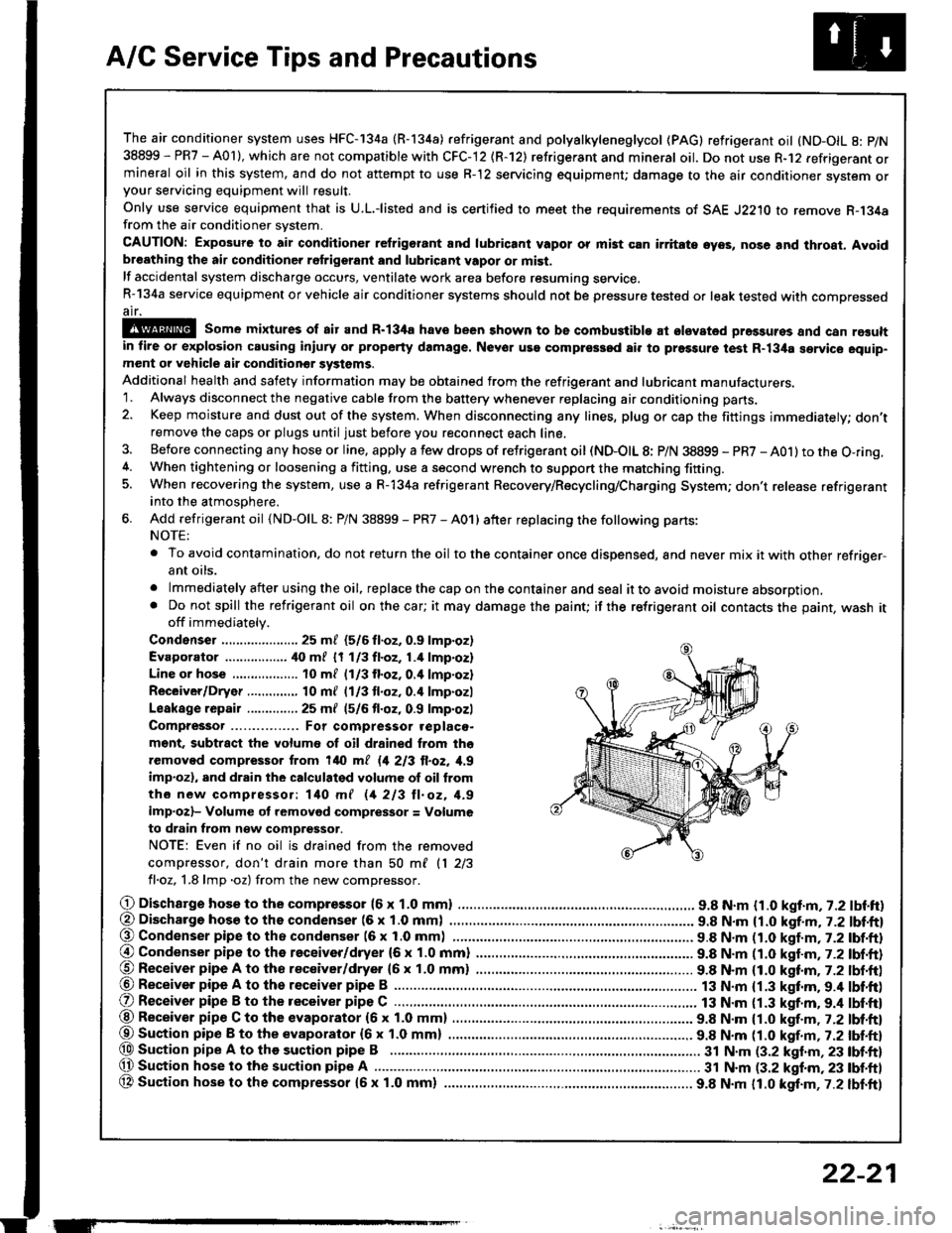
O Dischargo hose to the compresso. (6 x 1.0 mml .............................. 9.8 N.m {1.0 kgt.m, 7.2 lbf.ft)(, Discharge hosa to ths condenser (6 x 1.0 mm) . 9.8 N.m {1.0 kgf.m, j.Z lbl.ftl@ Condenser pipe to tho condenser (6 x 1.0 mml 9.8 N.m n.O kaf.m,t-2tbl.ftl
@ Condenser pipe to the receiver/dryer (6 x 1.0 mm) ......................... 9.8 N.m (1.0 katm,7.2 lbf.ft)@ Receiver pipe A to tho receiver/dryer 16 x 1.0 mm) ......................... 9.8 N.m (1.0 kttm. 7.2 lbt.ft)@ Receiver pipe A to th6 receiver pipe B ......................................
O Receiver pipe B to the receiver pipe C .............................................. 13 N.m {1.3 kgt.m. 9.4 lbt'ft)
13 N.m {1.3 kgf.m.9.4 lbf'ft)@ Receiver pipe C to the evaporator (6 x 1.0 mm) 9.8 N.m {1.0 kgf.m , j.Zlbl.ftl
@Suaion pip€ B to the evaporator {6x 1.0 mm) ................ ................ 9.8 N.m tt.O t!f.-, r.Z tUt tt}@ Sustion pipe A to the suction pipe B .................. 3t N.m (3.2 klnm,23 lbf.ft)(, Suction hose lo the suction pipe A ................ ...... 31 N.m (3.2 kgf.m, 23 tbf.ftl
OA Suction hose to the compressor {5x 1.0 mm} ................ ................. 9.8 N.m 11.0 kgt.m,7.2 lbf.ft)
ET
22-21