1994 HONDA INTEGRA Dash
[x] Cancel search: DashPage 1240 of 1413
A/T Gear Position Indicator
Indicator Input Test
CAUTION:
a All SRS electrical widng harn6ssos ara cov6r6d whh
yellow insulation.
a Before disconnecting any part ot the SRS wiro hEr-
ness. connect the shon connoctolls).
a Replace the entire affectod SRS harnosr assombly il
it has an op€n circuit or damaged wiring.
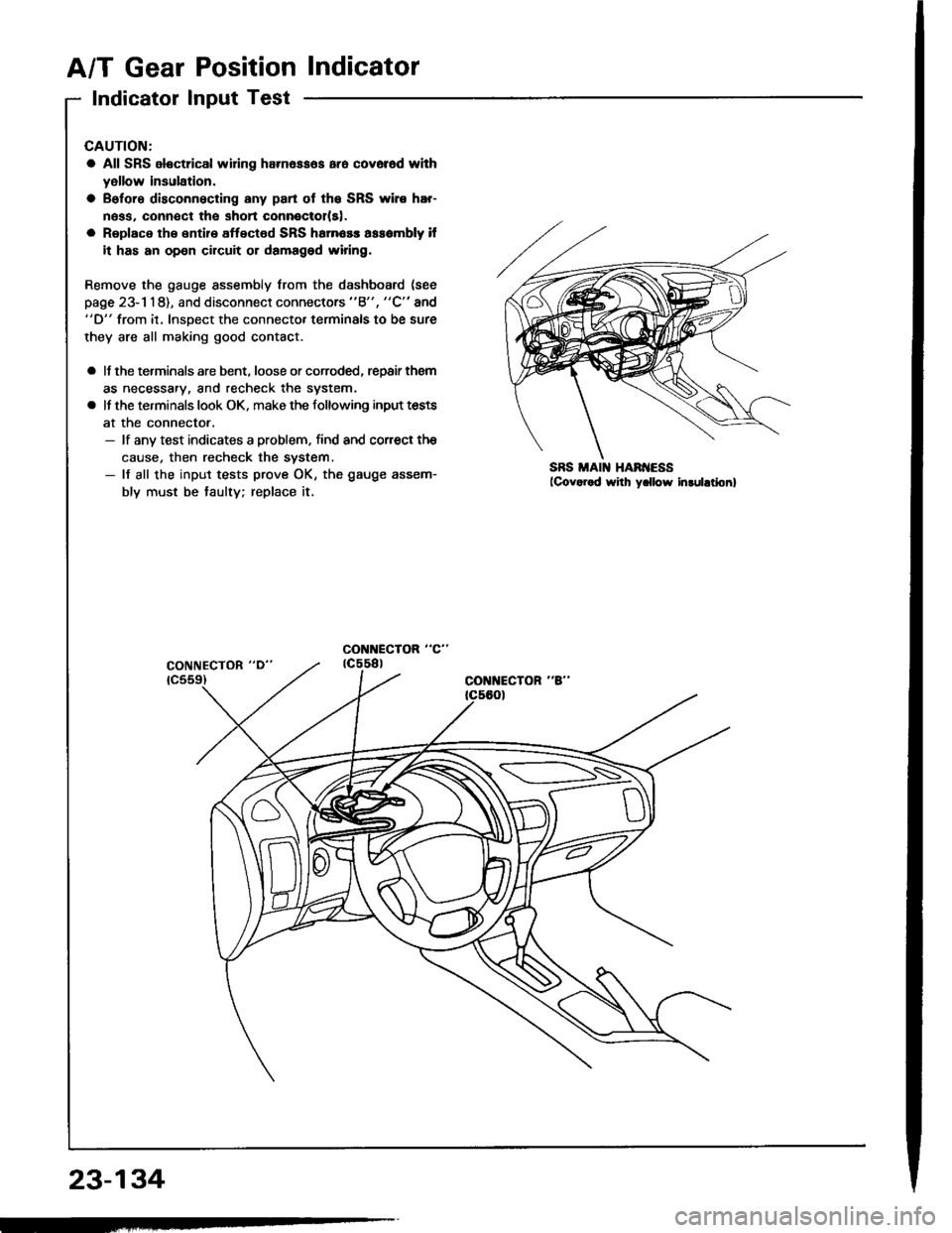
Remove the gauge assembly from the dashboard (see
page 23- l 1 8), and disconnect connectors "8", "C" and"D" from it. lnsoect the connecto. terminals to be sure
they are all making good contact.
a lf the terminals are bent. loose or corroded, repair them
as necessary, and recheck the system.
a lf the terminals look OK, make the following input tests
at the connector.- lf any test indicates a problem, find and corect the
cause, then recheck the system.- lf all the input tests prove OK, the gauge assem-
bly must be taulty; replace it.
CONI{ECTOR "8"
SS
23-134
Page 1241 of 1413
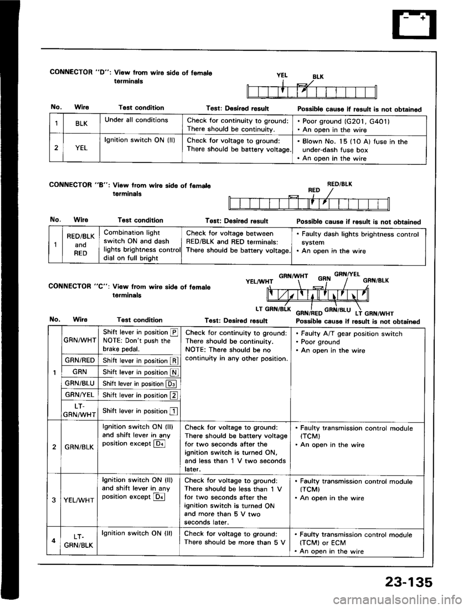
CONNECTOR "D": Visw from wire side ot femals
tetminals
No.WilaTest condition
CONNECTOR "8": View from wire sid6 of fem.l6
i6lminals
No.WileTost condition
CONNECTOR "C": Vi3w lrom wire sido of temale
t6rminals
Test condition
Test: D€sirod rasultPossible cause if result is not obtainod
Tost: D€sir6d resultPossiblo cause if result is not obtained
GRNA HTGRNITELYELAA'HTGRN/BLK
Tost: Desirod r6sult Possible cause it result is not obtainedNo.
BLKUnder all conditionsCheck for continuity to ground:
There should be continuitv.
. Poor ground (G2O1, G4O1). An open in the wire
2YEL
lgnition switch ON { ll}Check for voltage to ground:
There should be battery voltage.
. Blown No. 15 (1O A) tuse in the
under-dash fuse box. An open in the wire
RED/BLK
1
RED/BLK
ano
RED
Combination light
switch ON and dash
lights brighlness control
dial on full bright
Check for voltage between
RED/BLK and RED terminals:
There should be baftery voltage.
. Faulty dash lights b.ightness control
system. An open in the wire
GRN^^/HT
Shift lever in position @NOTE: Don't push the
brake pedal.
Check for continuity to ground:
There should be continuitv.
NOTE: There should be no
continuity in any other position.
Faulty A/T gear position switch
Poor ground
An open in the wire
GRN/REDShift lever in position @
GRNShift lever in position S
GRN/BLUShitr lever in position @
GRN/YELShitt lever in position f2 ]
LT-
GRNMHTShift lever in position E
2GRN/BLK
lgnition switch ON (ll)
and shift lever in anyposition except @
Check for voltage to ground:
There should be battery voltage
for two seconds after the
ignition switch is turned ON,
and less than 1 V two seconds
later.
. Faulty t,ansmission control module(TCM)
. An open in the wire
3YEL/vVHT
lgnition switch ON (ll)
and shitt lever in anyposition except @
Check for voltage to ground:
There should be less than 'l V
tor two seconds after the
ignition switch is turned ON
and more than 5 V two
seconds later.
. Faulty transmission control modute(TCMI
. An open in the wire
4LT.
GRN/BLK
lgnition swirch ON {ll}Check for voltage to ground:
There should be mofe than 5 V
. Faulty transmission control module
ITCM) or ECM. An open in the wire
23-135
Page 1247 of 1413
Control Unit Input Test
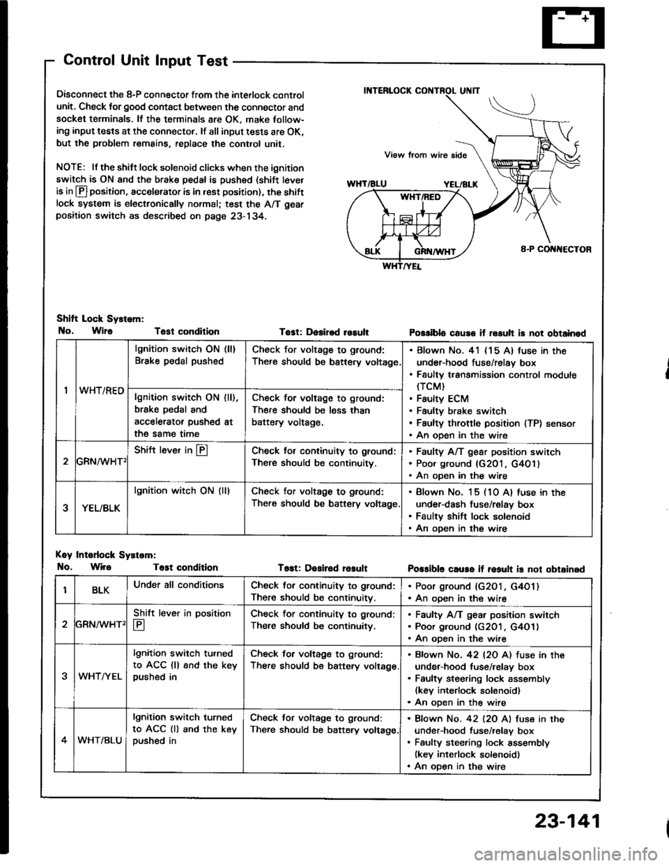
Oisconnect the 8-P connector from the interlock control
unit. Check for good contact between the connector and
socket terminals. lf the terminals 8re OK, make Iollow-
ing input tests at the connector. lf all input tests are OK,
but the problem remains, replace the cont.ol unit,
NOTE: lf the shilt lock solenoid clicks when the ignition
switch is ON and the brake pedal is pushed (shift tever
is in lfl position, accelerator is in rest position), the shiftlock system is electronically normal; test the A/T gear
positaon switch as described on page 23- 134.
Shift Lock Sy.tem:
No, Wlr6 Tost condition
Koy Intodock Systam:
No. WireT6st condition
Tost: Dosired resultPossiblo cause if rssuh is not obtainod
T6st: Desiled reaultPossible caure if rosult is not obtainsd
'I
lgnition switch ON (ll)
Brake pedal pushedCheck for voltage to ground:
There should be bsttery voltage
Blown No. 41 (15 A) fuse in the
under-hood fuse/relay box
Faulty transmission control module(TCM}
Faulty ECM
Faultv brake switch
Faulty throftle position lTP) sensor
An oDen in the wire
wn t/hEulgnition switch ON
brske pedal and
accelerator pushed
the same time
I [),
at
Check for voltage to ground:
There should be less than
battery voltage.
GRN^/vHT'
Shift lever in @Check lol continuity to ground:
There should be continuity.
Faulty A/T gear position switch
Poor ground {G201, G401}
An oDen in the wire
YEL/BLK
lgnition witch ON (lllCheck for voltage to ground:
There should be battery voltage
Blown No. 15 (10 A) luse in the
under-dash fuse/relay box
Faulty shift lock solenoid
An oDen in the wire
BLKUnder all conditionsCheck for continuity to ground:
There should be continuitv.
. Poor ground (G2O1, G4O1). An ooen in the wire
2
Shift lever in position
E
Check for continuity to ground;
Ther€ should be continuity.
Faulty A/T gear position swirch
Poor ground (c2O1 , G4O1)
An oDen in the wire
3WHTAYEL
lgnition switch tu.ned
to ACC (ll 8nd the keypushed in
Check for voltage to ground:
There should be battery voltage
Bfown No. 42 l2O Al fuse in the
under-hood tuse/relay box
Faulty steering lock assembly(kev interlock solonoid)
An oDen in the wire
4WHT/BLU
lgnition switch turned
to ACC (ll and the keypushed in
Check tor voltage to ground:
There should be batery voltage,
Bfown No. 42 l2O Al fuse in the
under-hood fuse/relav box
Faulty steering lock assembly(key interlock solenoid)
An oDen in the wire
23-141
Page 1248 of 1413
Interlock System
Kev Interlock SolenoidTestKey IntenocK Dorenoro I esr -
CAUTION:
a All SRS electrical wiring harnesses ar€ covered rYith
yollow insulation.
a 8eforc disconnecting any pan of the SRS wire har-
ness. connecl tha short connoclol{s|.
a Raplace the ontire affected SRS harness assembly if
it has an opon circuit or damaged wiring,
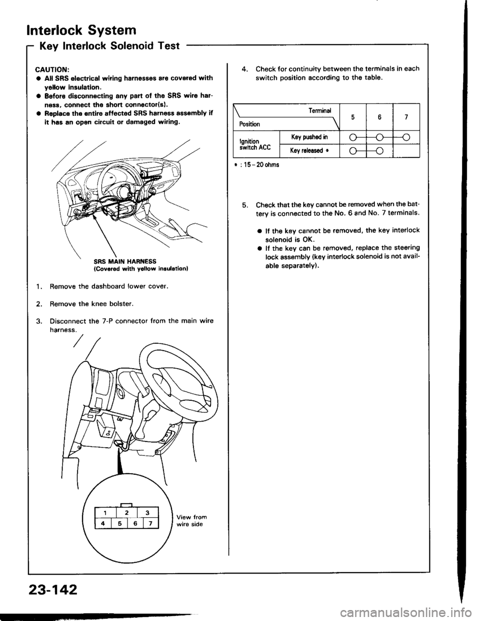
4. Check for continuitv between the terminals in each
switch position according to the table.
5, Check that the key cannot be removed when the bat-
tery is connected to the No. 6 8nd No. 7 terminals.
a It the kev cannot be removed, the key interlock
solenoid is OK.
a lf the key can be removed, replace the steering
lock assembly (key interlock solenoid is not avail-
able separately).
1.Remove the dashboard lower cover
Remove the knee bolster.
Disconnect
narness.
the 7-P connector from the main wire
\______________rry
Position7
lonitionS hch Acc
Koy push€d ino---o
Koy roleEsod r--o
* : l5-20ohms
{Covorod with yollow inlulrtionl
23-142
Page 1250 of 1413
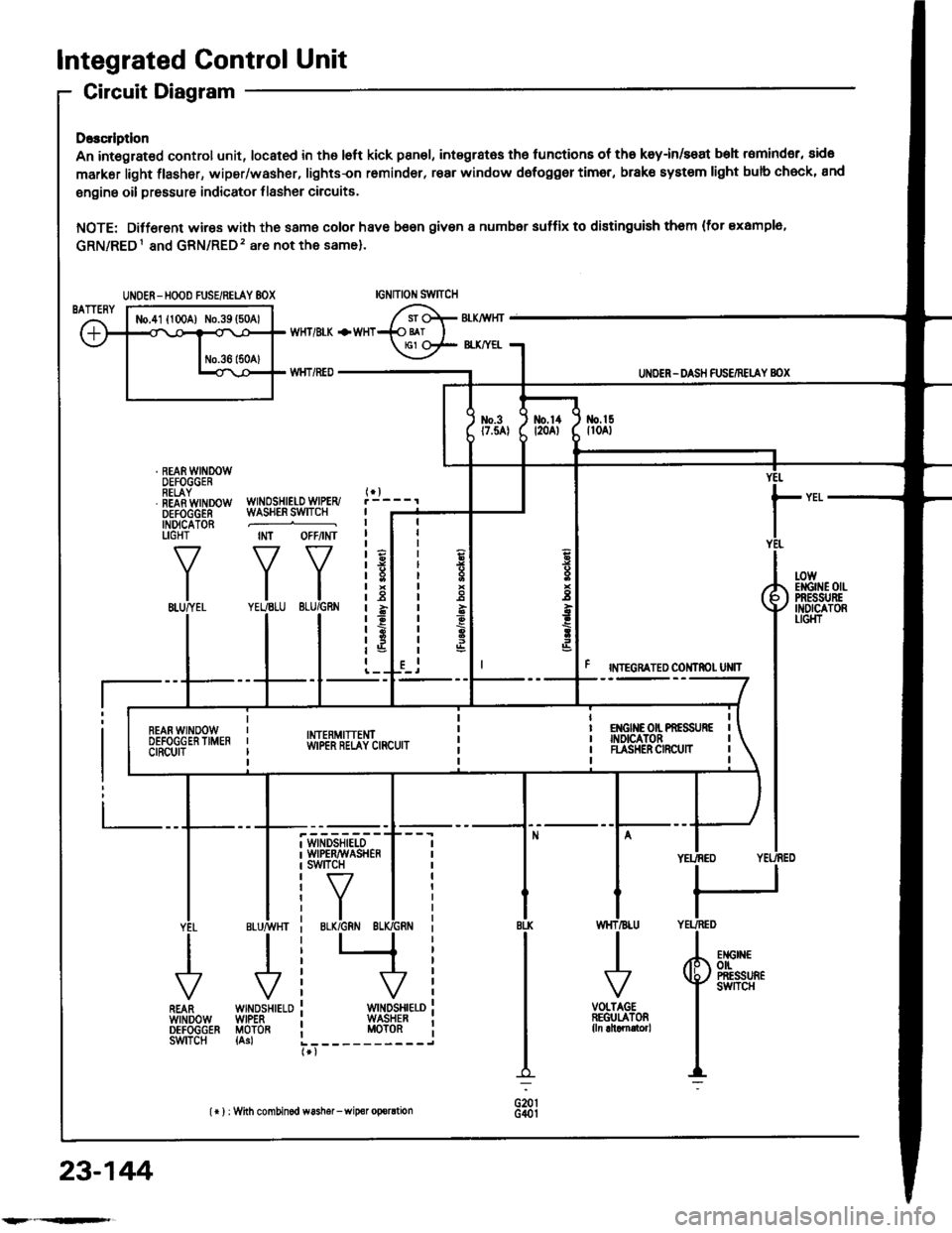
Integrated Control Unit
Circuit Diagram
D.3c ptlon
An integrat€d control unit, located in the left kick panel, integratss the functions of tho keyin/seat beh r6mind€r, sido
markar light {lasher, wiper/washer, lights-on r6minder, rear window dsfogger timer, brak€ system light bulb check, and
enging oil pressure indicator flasher circuitE,
NOTE: Difforent wires with the same color have be6n given a numbor suffix to distinguish them (for Example,
GRN/RED1 and GRN/RED'� are not the same).
WNOSHIELD WIPER/WASHER SWITCH
IMT OFFiINT
I
II
IIIIIIIIIIII
YEUEE
rl
t
P
UNOER - DASH FUS€/RETAY BOX
r NTEGRATED COI{TROI UNIT
t-0wErGrilE 0|lPRESSI'REINDICATORLIGI{T
WINDSHIELOWIPERAVASHERswtTcH
tr-/
IBLK/GRN BI
WINDSHIELOWIPERMOTOR{Asl
VOLTAGEREGULATOR{ln ahamator,
UNOER- HOOD FUSE/RELAY 8OX
I
r3
r8relit;rBt5I
23-144
lr ) : With combinod washef-wip€r oporation
Page 1252 of 1413

Integrated Control Unit
Input Test
CAUTION:
a All SRS elocttical widng hatness€s ato covored with
yollow insulation.
a Botolo disconnocring any pan ot the SRS wile hal'
ness, conn€ct tho shon connoctor(3l.
a Replaca tho ontlrg affsctod SRS hE noaa assombly if
it has an opon circuit or damag6d wifng.
Remove the dashboSrd lower cover and knee bolstar.
then disconnect the 1 5-P connector Jrom the integratsd
control unit.
Remove the integrated control unit from the under-dash
Juse/relav box.
Inspect the connector and socket tetminals to be sure
they are all making good cont8ct.
a lf the terminals are bent, loose ot corrod€d, repair them
as necessary, and recheck the system
a lf the terminals look OK, make the tollowing input tssts
at the connector and under-dash tuse/relsy box.
- lf any test indicates a problem, find and correct the
cause, then recheck the system.- It all the input tests prove OK, the control unit must
be faulty; replace it.
15.P CONNECTOR
NOTE:
a Diftorent wires with the sam€ color have been given
a number suffix to distinguish th€n {for 6xample,
GRN/BLUI and GRN/BLU'�are not the same).
a Do not disconnect any connectors on tho under-dash
fu8e/relay box except the integratsd contlol unit.
BLU/WHT I BLU/GR]{ I BLU/YEL I LT GB /BED
23-146
SRS MAII{ HARI{ESS
H_____-t{
.BLK/GBI{ LT
YEL/BLU GRN/BLUI GRI{/RED
Page 1253 of 1413
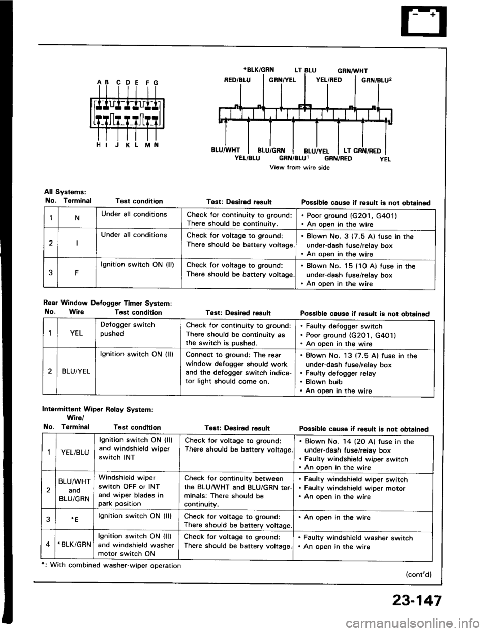
1NUnder all conditionsCheck for continuity to ground:
There should be continuitv.
. Poor ground (G201, G4O1). An open in the wire
Under all conditionsCheck for voltage to ground:
There should be battery voltage.
. Blown No. 3 (7.5 A) fuse in the
under-dash fuse/relay box. An oDen in the wire
F
lgnition switch ON {ll)Check for voltage to ground:
There should be bsttery voltage
. Blown No. 15 (10 A) tuse in the
under-dash fuse/relay box. An open in the wire
All Systems:
No. TsrminalT€st condition
R€ar Window Detogger Timer System:
No. WireTost condition
Intermittent Wip6r Relay System:
Wir€/
No. TerminalTest condition
T6st: Desired rosult
Test: Dosiled result
T€Et: Desir6d result
Possibla cause it result is not obtained
Possible cause il rosult i8 not obtained
Possiblo cause if rosult is not obtained
(cont'd)
IYEL
Defogger switchpushedCheck lor continuity to ground:
There should be continuity asthe switch is Dushed.
Faulty defogger switch
Poor ground {G201, G4O1}
An open in the wire
BLUiYEL
lgnition switch ON (ll)Connect to ground: The rear
window defogger should work
and the detogger switch indica-
tor light should come on.
Blown No. 13 {7.5 Al fuse in the
under-dash fuse/relay box
Faulty defogger relay
Blown bulb
An open in the wire
,|YEL/BLU
lgnition switch ON (ll)
and windshield wipet
switch INT
Check tor voltage to ground:
There should be battery voltage
Bfown No. '14 l2O Al fuse in the
under-dash fuse/relay box
Faulty windshield wiper switch
An oDen in the wire
BLU/WHT
ano
BLUiGRN
Windshield wiper
switch OFF or INT
and wiper blades inpark position
Check for continuity between
the BLUMHT and BLU/GRN ter-minals: There should be
continuity.
Faulty windshield wiper switch
Faultv windshield wiDer motor
An open in the wire
.Elgnition switch ON (lllCheck for voltage to ground:
There should be battery voltage.
. An open in the wire
*BLK/GRNlgnition switch ON (ll)
and windshield washer
motor switch ON
Check for voltage to ground:
There should be battery voltage.
. Faulty windshield washer switch. An open in the wire
*: With combined washer-wiper operation
23-147
Page 1254 of 1413
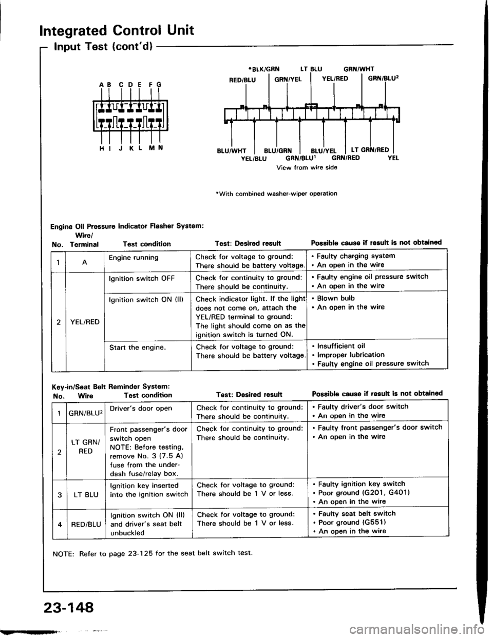
Integrated Control Unit
Input Test (cont'd)
Engine Oil Pressure Indicator Flashal System:
Wire/
rWith combined washeFwipot operation
Test: Desired resultPossiblo c€use if r6rult is not obtainodNo. TelminalTsst condition
M
1Engine runningCheck for voltage to ground:
There should be battery voltage
. Faulty charging system. An oDen in the wire
YEL/RED
lgnition switch oFFCheck for continuity to gtound:
There should be continuitv.
. Faulty engine oil ptessure switch
. An oDen in the wire
lgnition switch ON (ll)Check indicator light. lf the light
does not come on, Sttach the
YEL/RED terminal to ground:
The light should come on as the
ignition switch is turned ON.
. Blown bulb. An open in the ware
Start the engine.Check for voltage to ground:
There should be battery voltage
Insufficient oil
lmproper lubrication
Faulty engine oil pressure switch
Key-in/Seat Bolt Reminder Systam:
No. WilaTest condition
NOTE: Refer to page 23-125 for the seat belt switch test.
Test: Dosired lesuhPossible causo if resuh is not obtainod
23-148'
GRN/BLU'Driver's door openCheck for continuity to ground;
There should be continuitv.
. Faulty driver's door switch
. An ooen in the wire
LT GRN/
RED
Front passenger's door
switch open
NOTE: Betore testing,
remove No. 3 (7.5 A)
tuse from the under-
dash fuse/relay box.
Check tor continuity to ground:
There should be continuitv.
. Faulty lront passenger's door switch
. An ooen in the wire
LT BLU
lgnition key inserted
into the ignition switch
Check for voltage to ground:
There should be 1 V or less.
Faulty ignition key switch
Poor ground (G201 , G401)
An ooen in the wite
RED/BLU
lgnition switch ON (ll)
and driver's seat belt
unbuckled
Check lor voltage to ground:
There should be 1 V or less.
Faulty seat belt switch
Poor ground {G551)
An open in the wire
;.rqFft,