Page 33 of 225

ia.14 Every 20 000 miles - petrol models
16 Test the operation of the brake servo unit as follows. With the engine off, depress the footbrake four or five times to exhaust the vacuum. Hold the brake pedal depressed, then start the engine. As the engine starts.
there should be a noticeable give In the brake pedal as vacuum builds up. Allow the engine to run for at least tsvo minutes, and then switch it off. If the brake pedal is depressed now. it should be possible to detect a hiss
from the servo as the pedal is depressed. After about four or five applications, no further hissing should be heard, and the pedal shouto feel considerably harder.
Every 30 000 miles (45 000 km) or 3 years
. transmission (see illustration). Using an Allen 25 Lambda/oxygen sensor ^ key, unscrew the plug and clean it. check \ 3 The oil level should reach the lower edge of ^ the filler/level hole. A certain amount of oil will have gathered behind the filler/level plug, and If the CO level at the exhaust tailpipe is too w,u tr,cWe out when is 'e™oved; this does high or low, Ihe vehicle should be taken to a «©l necessarily Indicate that the level is Fiat dealer so lhat the complete fuel-injection correct. To ensure that a true level is and ignition systems, including the Lamoda/ established, wait until the Initial trickle has oxygen sensor, can be thoroughly checked stopped, then ado oil as necessary until a using the special diagnostic equipment. Once ,r,ckle o1 new oil can be seen emerging. The these have been checked and are known to 'W wl" be correct when ,he flow ceases-us® be free from faults, the fault must be in the good-quality oil of the specified type, catalytic converter, which must be renewed Make sur®that vehicle Is completely level as described In Chapter 4D, Section 6. checking the level and do not overfill, 4 When the level Is correct refit and tighten the plug and wipe away any spilt oil.
26 Manual transmission oil level check ^ 27 Evaporative loss system ^ check
1 Park Ihe vehicle on a level surface, If possible over an inspection pit or on a ramp as the filler/level plug is best reached from under Ihe engine compartment. The oil level must be checked before the car is driven, or at least 5 minutes after the engine has been switched off. If the oil ts checked Immediately alter driving the car, some of the oil will remain distributed around the transmission components, resulting in an inaccurate level reading. 2 Wipe clean the area around the filler/level plug, which is situated on the front of the
Refer to Chapter 40 Section 2 and check that all wiring and hoses are correctly connected to the evaporative toss system components.
28 Automatic transmission fitter and fluid change
1 Take the vehicle on a short run. to warm the transmission up to operating temperature.
Park the car on level ground, then switch off the Ignition. 2 Firmly apply the handbrake, then jack up the front of the car and support It securely on axle stands (see Jacking and vehicle support]. Note thai, when refilling and checking Uie fluid level, the car must be lowered to the ground, and level, to ensure accuracy. 3 Remove the dipstick, then position a suitable container under the transmission, Unscrew the sump drain plug and allow the fluid to drain for at ieast 10 minutes. Refit and tighten the drain plug when the fluid has completely drained.
A
Warning: The transmission fluid may be very hot and precautions must be taken to avoid scalding.
4 Clean around the transmission sump mating flange. Unboll and remove the sump and remove the gasket. 5 Remove the two bolts and withdraw the transmission fluid filter {see illustration). 6 Fit the new filter, and secure It with the two bolts. 7 Refit the sump using a new gasket, then
_
lower the vehicle to the ground, 8 Fill the transmission with the specified quantity of fluid via Ihe dipstick tube, using a funnel with a fine mesh filter. 9 Run the engine to normal operating temperature, then check the fluid level as described In Weekly checks. 10 Dispose of the old fluid safely.
26.2 Transmission filler/level plug location 28.5 Automatic transmission fluid filter retaining bolts
Page 34 of 225
 or 4 years
29 Rear brake shoe check
1 Chock the front wheels then Jack up the rear of Ihe car and support it on axle sta")
Maintenance procedures - petrol models 1A.15
Every 40 000 miles (60 000 km) or 4 years
29 Rear brake shoe check
1 Chock the front wheels then Jack up the rear of Ihe car and support it on axle stands (see Jacking and Vehicle Support). Remove the rear roadwheels. 2 Using the inspection hole at the edge of the brake drum, check that the linings are not worn below Ihe minimum thickness given in the Specifications (see illustration). If necessary use a torch. 3 If the friction material on any shoe is worn down to the specified minimum thickness or
less,
all four shoes must be renewed as a set. 4 At the same time check for signs of brake
Kutti
leakage. 5 For a comprehensive check, the brake drum should be removed and cleaned. This
will allow the wheel cylinders to be checked, and the condition of the brake drum itself to be fully examined (see Chapter 9). 6 Refit the lubber plugs then lower the car to the ground.
30 Timing belt renewal
Refer to Chapter 2A or 2B. Note: Although the norma/ interval for timing belt renewal is 70 000 miles (105 000 km), it is strongly recommended that the interval Is reduced on vehicles which are subjected to intensive use. ie, mainly short journeys or a lot of stop-start driving. The actual belt renewal interval is therefore very much up to the individuaf owner. That being said, it is highly recommended to err on the side of safety, and
29.2 Check the thickness of the shoe friction material through the hole on the edge of the drum (arrowed)
renew the belt at 40 000 miles (60 000 km), bearing in mind the drastic consequences resulting from belt failure.
Every 60 000 miles (90 000 km) or 6 years
31 Emission control system check
Refer to Chapter 4D. A full check of the emissions control systems must be made by a Fiat dealer.
Every 80 000 miles (120 000 km)
32 Manual transmission all renewal S
1 Park the vehicle on a level surface, if possible over an inspection pit or on a ramp as the filler/level and drain plugs are accessed from order
the
engine compartment. If necessary
Jack
ip the vehicle and support on axle stands (see
Jacking and vehicle
support). 2 Wipe clean the area around the filler/leval And drain plugs, which are on the front and bottom of the transmission (see illustration).
3 Using an Allen key. unscrew the filler/level plug and clean it. 4 Position a suitable container beneath the transmission, then use the Allen key to unscrew the drain plug. Allow the oil to completely drain. 5 Wipe clean the drain plug then refit and tighten It. 6 Fill the transmission with ihe correct grade and quantity of oil, referring to Section 26 when checking the level. Refit and lighten the filler/level plug. 7 Where applicable lower the vehicle to the ground. 32.2 Transmission drain plug location (viewed from under the vehicle)
Every 2 years (regardless of mileage)
33 Coolant renewal
I
Cooling system draining
A
Warning: Walt until the engine Is cold before starting this pro-cedure. Do not allow antifreeze to come In contact with your skin, or with the painted surfaces of the vehicle. Rinse off spills immediately with plenty of water.
Ndver
leave antifreeze lying around In an open container, or fn a puddle In the
driveway or on the garage floor. Children and pets are attracted by its sweet smell, but ant/freeze can be fatal if ingested. 1 With the engine completely cold, cover the expansion tank cap with a wad of rag. and slowly turn the cap anticlockwise to relieve the pressure in the cooling system (a hissing sound will normally be heard). Wait until any pressure remaining in the system is released, then continue to tum the cap until it can be removed. 2 Position a suitable container beneath the radiator bottom hose connection, then release the retaining clip and ease the hose from the radiator stub (see illustration). If the hose 33.2 Disconnecting the radiator bottom hose to drain tho coolant
Page 35 of 225

ia.16 Every 2 years - petrol models
joint has not been disturbed for some time, if will bo necessary to gently manipulate the hose to break the joint. Do not use excessive force, or the radiator stub could be damaged. Allow the coolant to drain Into the container. 3 Certain models are fitted with cooling system bleed plugs, which should be opened to aid the draining process and help prevent airlocks. These are located on the top right hand edge of the radiator, on the heater Inlet hose and additionally, on 16-valve engines, on the heater outlet hose (see illustrations). If the coolant has been drained for a reason other than renewal, then provided It is ciean and less than two years old, it can be re-used, though this is not recommended. 4 Once ail the coofant has drained, reconnect the hose to the radiator and secure it in position with the retaining clip.
Cooling system flushing 5 If coolant renewal has been neglected, or If the antifreeze mixture has become diluted, then in time, Ihe cooling system may gradually lose efficiency, as the coolant passages become restricted due to rust, scale deposits, and other sediment. The cooling system efficiency can be restored by flushing the system clean. 6 The radiator should be flushed Independently of the engine, to avoid contamination. Radiator flushing 7 To flush the radiator disconnect the top and bottom hoses and any other relevant hoses from the radiator, with reference to Chapter 3. 8 Insert a garden hose into the radiator top inlet. Direct a flow of clean v/ater through the radiator, and continue flushing until clean water emerges from the radiator bottom outlet. 9 If after a reasonable period, the water still does not run clear, the radiator can be flushed wilh a good propnetary cooling system
cleaning agent. It is important that their manufacturer's Instructions are followed carefully. If the contamination is particularly bad, insert the hose in the radiator bottom outlet, and reverse-flush the radiator. Engine flushing 10 To flush the engine, remove the thermostat as described In Chapter 3 then temporarily refit the thermostat cover. 11 With the top and bottom hoses disconnected from the radiator, insert a garden hose into the radiator top hose. Direct a clean flow of water through the engine, and continue flushing until clean water emerges from the radiator bottom hose. 12 On complotion of flushing, refit the thermostat and reconnect the hoses with reference to Chapter 3,
Cooling system filling 13 Before attempting to fill the cooling system, make sure that all hoses and clips are in good condition, and that the clips are tight. Note that an antifreezo mixture must be used all year round, to prevent corrosion of the engine components (see below). 14 Remove the expansion tank filler cap. and fill the system by slowly pouring the coolant Into the oxpansion lank to prevent airlocks from forming. Ensure that all bleed plugs/screws are open. 15 If the coolant Is being renewed, begin by pouring in a couple of litres of v/ater, followed by the correct quantity of antifreeze, then top-up with more water. 16 Once the level in the expansion tank starts to rise, squeeze the radiator top and bottom hoses to help expel any trapped air In the system. Once all the air is expelled, top-up the coolant level to the MAX mark and refit the expansion tank cap. Close all bleed plugs. Continue the filling procedure as follows according to engine type.
1108 cc and 1242 cc (8-vaive) engines 17 Start the engine and run it until tt reaches normal operating temperature, then stop the engine and allow it to cool. 18 Chock for teaks, particularly around disturbed components. Check the coolant level in the expansion tank, and top-up H necessary. Note that the system must be coW before an accurate level Is indicated in the oxpansion tank. If the expansion tank cap is removed while the engine Is still warm, cover Ihe cap with a thick cloth, and unscrew the cap slowly to gradually relieve the system pressure (a hissing sound will normally be heard). Wall until any pressure remaining In the system is released, then continue to turn the cap until It can be removed. 1242 cc (16-valve) engines 19 Remove the expansion tank filler cap. start the engine and run it at Idling speed for two to three minutes. Allow the engine to continue running until the electric cooling fan operates, but during this time, briefly in-crease the engine speed to 2000 to 3000 rpm every 30 seconds. Maintain the coolant level in the expansion tank to the MAX mark during tliis procedure, adding more coolant as necessary. 20 On models without air conditfoning, wilh the engine still idling, carefully unscrew the bleed plug on the top of the radiator. Increase the engine speed until fluid emerges from the bleed plug, then close the plug and return the engine to idle.
A
Warning: Take suitable pre-cautions against scalding when opening the bleed plug as the coolant will be very hot. 21 On all models, allow the engine to continue running at idle for a further five minutes. After this time, switch the engine ofl, allow it 1o cool completely and when cool
Page 36 of 225

Every 2 years - petrol models ia.i?
check, and if necessary top-up, the level in the expansion tank. Refit the cap on completion. Antifreeze mixture 22 The antifreeze should always be renewed at the specified Intervals. This is necessary not only to maintain the antifreeze properties, but also to prevent corrosion which would otherwise occur as the corrosion inhibitors
beoome
progressively less effective. 23 Always use an ethylene-glycol based antifreeze which Is suitable for use In mixed-metal cooling systems, The quantity of antifreeze and levels of protection are
Indicated In
the Specifications. 24 8efore adding antifreeze, the cooling system should be completely drained, preferably flushed, and all hoses checked for condition and security. 25 After filling with antifreeze, a label should
be attached
to the expansion tank, stating the type and concentration of antifreeze used, and the date installed. Any subsequent lopping-up should be made with the same
type and
concentration of antifreeze. 26 Do not use engine antifreeze In the windscreen/tailgate washer system, as it will
cause damage to the vehicle paintwork. A screenwash additive should be added to the washer system in the quantities stated on the bottle.
34 Brake fluid renewal | I
A
Warning: Brake hydraulic fluid can harm your eyes and damage painted surfaces, so use extreme caution when handling and pouring H. Do not use fluid that has been standing open for some t/me, as it absorbs moisture from the air. excess moisture can cause a dangerous ioss of braking effectiveness. 1 The procedure is similar to that for the bleeding of the hydraulic system as described in Chapter 9, except that the brake fluid reservoir should be emptied by siphoning, using a clean poultry baster or similar before starting, and allowance should be made for the old fluid to be expelled when bleeding a section of the circuit. 2 Working as described In Chapter 9, open the first bleed screw in the sequence, and
pump the brake pedal gently until nearly all the old fluid has bsen emptied from the master cylinder reservoir.
Old hydraulic fluid Is Invariably much darker In colour than the new, making It easy to distinguish the two.
3 Top-up to the MAX level with new fluid, and continue pumping until onty the new fluid remans in the reservoir, and new fluid can be seen emerging from the bleed screw. Tighten the screw, and top the reservoir level up to the MAX level line. 4 Work through all the remaining bleed screws in the sequence until new fluid can be seen at all of them. Be careful to keep the master cylinder reservoir topped-up to above the MIN level et all times, or air may enter the system and greatly increase the length of the task. 5 When the operation Is complete, check that all bleed screws are securely tightened, and that their dust caps are refitted. Wash off all traces of spilt fluid, and recheck the master cylinder reservoir fluid level. 6 Check the operation of the brakes before taking the car on the road.
1A
Page 37 of 225
 check and renewal 16 Brake fluid renewal 2d Brake warning lamp oper")
1B»1
Chapter
1
Part B:
Routine maintenance & servicing - diesel models
Contents
Air filter renewal 13 Auxiliary drivebelt(s) check and renewal 16 Brake fluid renewal 2d Brake warning lamp operation check 5 Clutch adjustment check 17 Coolant renewal 27 Drtv«shaft gaiter check 10 Emissions control systems check 25
Engage
oil and filter renewal 3 Exhaust system check 9 Front brake pad check 6
Fuel
fitter renewal 12 Fuel Filter water draining 4 Headlight beam adjustment 20
Hinge and lock lubrication 19 Hose and fluid leak check 6 Idle speed check and adjustmenl 11 Introduction ... 1 Manual transmission oil level check 22 Manual transmission oil renewal - 26 Pollen filter renewal 14 Rear brake shoe check 23 Regular maintenance 2 Road test 21 Steering and suspension check 15 Timing belt renewal 24 Underbody sealant check 7 Valve clearance check and adjustment 16
^m
Degrees of difficulty
Easy, sutable for % Fairly easy, suitable FaHycifficult, i'. Difficult, suitable fa Very difficult, novice with irttte % for beginner with suitable for competent experienced DIY
1
suitable for expert DIY * or professional jQ experience some experience DIY mechanic mechanic 1
suitable for expert DIY * or professional jQ
Page 38 of 225
 Non-turbo diesei engine 4.95 litres Turbo die")
1B.2
Servicing specifications - diesel models
Lubricants and fluids Refer to end of Weekly checks on page 0*17
Capacities Engine oil (including filter) Non-turbo diesei engine 4.95 litres Turbo diesel engine 4.84 litres Cooling system 7.2 litres
Manual transmission Non-turbo diesel engine 2.37 litres Turbo diesei engine t .98 litres Power-assisted steering 0.65 litres
Fuel tank 47 litres Washer reservoir Without headlight washers 2.5 litres With headlight washers 7.0 litres
Engine Oil fitter Engine Idle speed: Non-turbo diesel engine Turbo diesel engine Auxiliary drivebelt tension ...... Valve clearances • engine cold: Inlet Exhaust
Champion C112
8l0«40rpm 900 ± 20 rpm 5.0 mm deflection midway between pulleys
0.30 mm * 0.05 mm 0.35 mm ± 0.05 mm
Cooling system Antifreeze mixture: 50% antifreeze Protection down to-35°C Note: Refer to antifreeze manufactuivr for latest recommendations.
Fuel system Air filter element: Non-turbo diesel engine (with Lucas/CAV Injection) Champion U611 Turbo diesel engine (with Bosch Injection) Champion U579 Fuel filter Champion L120
Brakes Brake pad lining minimum thickness 1-5 mm Brake shoe friction material minimum thickness 2.0 mm
Tyre pressures See end of Weekly checks on page 0*18
Torque wrench settings Fuel filter bracket to body ..... « Fuel filter to bracket i........ Manual transmission oil drain plug: Non-turbo diesel engine: Stage 1 Stage 2 Turbo diesel engine Manual transmission oil filler plug Roadwheel bolts
Nm Ibfft 18 13 24 18
12 9 Angle-tighten a further 180® 46 34 46 34
Page 39 of 225

Maintenance schedule - diesel models 1B.3
The mamtenance intervals in this manual are provided with the assumption that you. reI ihe dealer, will be carrying out the work.
These
are the minimum maintenance intervals recommended by us for vehicles driven daily.
ff you wish to keep your vehicle In peak condition at all times, you may wish to perform some of these procedures more often. We encourage frequent maintenance, because it enhances the efficiency.
performance and resale value of your vehicle. When the vehicle Is new, it should be serviced by a factory-authorised dealer service department, in order to preserve the factory warranty.
Every 250 miles (400 km) or weekly O Refer to Weekly checks
Every 5000 miles (7500 km) or
6
months - whichever comes first • Renew the engine oil and filter (Section 3) P Drain any water from the fuel filter (Section 4)
Every 10 000 miles (15 000 km) or
12
months - whichever comes first ill addition lo tho Items listed above, cany out the following; D Check the operation of the brake warning lamp J (Section 5) Check the front brake pads for wear (Section 6) :-G Check the underbody and sealant for damage j" (Section 7) n Hose and fluid leak check (Section 8) 0 Check the condition of the exhaust system and its 1 mountings (Section 9) -D Check the condition of the driveshaft gaiters ", (Section 10) O Check and adjust the idle speed (Section 11) ;0 Renew (he fuel filter (Section 12) J] Renew the air filter element (Section 13) L) Renew the pollen filter (Section 14) •• Check the steering and suspension components • for condition and security (Section 15)
Every 20 000 miles (30 000 km) or
2
years - whichever comes first In addition to the Items listed above, cany out the following: (P Check and if necessary adjust the tension of the auxiliary drlvebeltfs) (Section 16) '• Check the freeplay and height of the clutch pedal " (Section 17) D Check and if necessary adjust the valve clearances (Section 18) Lubricate all hinges and locks (Section 19) • Check the headlight beam adjustment (Section 20) O Cany out a road test (Section 21)
Every 30 000 miles (45 000 km) or
3 years - whichever comes first In addition to the Items listed above, cany out the following: • Check and if necessary top-up the manual transmission oil level (Section 22)
Every 40 000 miles (60 000 km) or
4 years - whichever comes first In addition to the items listed above, cany out the following: • Check the rear brake shoes for wear (Section 23) • Renew the timing belt (Section 24)'
•Note: Although the normal interval for timing belt renewal is 70 000 miles (ids 000 km), it is strongly recommended that the belt Is renewed at 40 000 miles (60 000 km) on vehicles which are subjected to intensive use, le. mainly short Journeys or a lot of stop-start driving. The actual bait renewal interval Is therefore very much up to the Individual owner, but bear in mind that sevefe engine damage will result if the belt breaks.
Every 60 000 miles (90 000 km) or
6 years - whichever comes first In addition to the Items listed above, cany out the following: • Check the condition and operation of the emission control system components (Section 25)
Every 80 000 miles (120 000 km) • Renew the manual transmission oil (Section 26)
Every 2 years
(regardless of mileage) • Renew the engine coolant (Section 27) • Renew the brake fluid (Section 28)
Page 40 of 225
ib-4 Component location - diesel models
Underbonnet view - turbo diesel model
1 Engine oil filter
cap
2 Engine oil dipstick 3 Oil
tilter
4 Brake/clutch fluid
reservoir
5 Air cleaner
cover
6 Power steering pump 7 Coolant expansion
tank
8 Windscreen washer
fluid
reservoir 9 Front suspension strut upper mounting 10 Fuel filter/heater
housing
11
Fuel
injection pump 12 Battery 13 Power steering fluid reservoir
Front underbody view - turbo diesel model
1 Oil
fitter
2 Sump drain plug 3 Transmission drain plug 4 Electric cooling fan unit 5 Left-hand
driveshaft
6 Intermediate
shaft
7 Bight-hand
driveshaft
8 Front suspension lower arms 9 Front anti-roll
bar
10 Exhaust downpipe 11 Front brake calipers 12
Rear
engine mounting 13 Radiator bottom hose
expert22 fl/ia http://rutracker.org
 1
1 2
2 3
3 4
4 5
5 6
6 7
7 8
8 9
9 10
10 11
11 12
12 13
13 14
14 15
15 16
16 17
17 18
18 19
19 20
20 21
21 22
22 23
23 24
24 25
25 26
26 27
27 28
28 29
29 30
30 31
31 32
32 33
33 34
34 35
35 36
36 37
37 38
38 39
39 40
40 41
41 42
42 43
43 44
44 45
45 46
46 47
47 48
48 49
49 50
50 51
51 52
52 53
53 54
54 55
55 56
56 57
57 58
58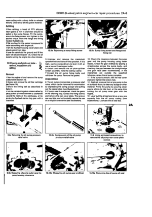 59
59 60
60 61
61 62
62 63
63 64
64 65
65 66
66 67
67 68
68 69
69 70
70 71
71 72
72 73
73 74
74 75
75 76
76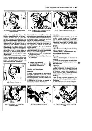 77
77 78
78 79
79 80
80 81
81 82
82 83
83 84
84 85
85 86
86 87
87 88
88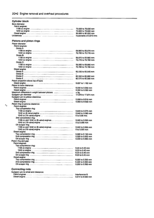 89
89 90
90 91
91 92
92 93
93 94
94 95
95 96
96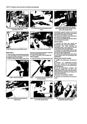 97
97 98
98 99
99 100
100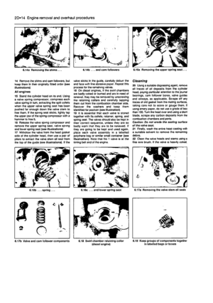 101
101 102
102 103
103 104
104 105
105 106
106 107
107 108
108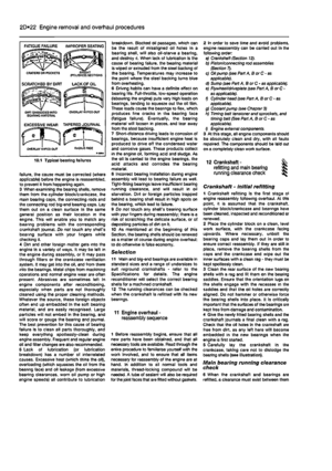 109
109 110
110 111
111 112
112 113
113 114
114 115
115 116
116 117
117 118
118 119
119 120
120 121
121 122
122 123
123 124
124 125
125 126
126 127
127 128
128 129
129 130
130 131
131 132
132 133
133 134
134 135
135 136
136 137
137 138
138 139
139 140
140 141
141 142
142 143
143 144
144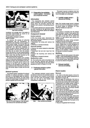 145
145 146
146 147
147 148
148 149
149 150
150 151
151 152
152 153
153 154
154 155
155 156
156 157
157 158
158 159
159 160
160 161
161 162
162 163
163 164
164 165
165 166
166 167
167 168
168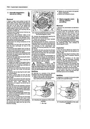 169
169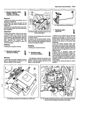 170
170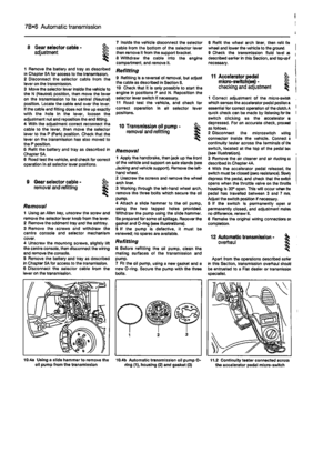 171
171 172
172 173
173 174
174 175
175 176
176 177
177 178
178 179
179 180
180 181
181 182
182 183
183 184
184 185
185 186
186 187
187 188
188 189
189 190
190 191
191 192
192 193
193 194
194 195
195 196
196 197
197 198
198 199
199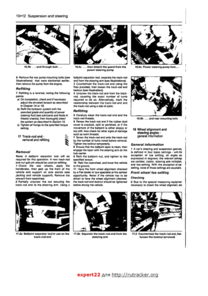 200
200 201
201 202
202 203
203 204
204 205
205 206
206 207
207 208
208 209
209 210
210 211
211 212
212 213
213 214
214 215
215 216
216 217
217 218
218 219
219 220
220 221
221 222
222 223
223 224
224