Page 105 of 225
 11 Scrape away all traces of carbon from the top of the piston. A hand-held wire brush (or a piece of fi")
2D*10 Engine removal and overhaul procedures
7.13 Positioning of piston rings (petrol engine) 11 Scrape away all traces of carbon from the top of the piston. A hand-held wire brush (or a piece of fine emery cloth) can be used, once the majority ot the deposits have been scraped away. 12 Remove the carbon from the ring grooves In the piston, using an old ring. Break the ring in half to do this (be careful not to cut your fingers - piston rings are sharp). Be careful to remove only the carbon deposits • do not remove any metal, end do not nick or scratch the sides of the ring grooves. 13 Once the deposits have been removed, clean the piston/connecting rod assembly with paraffin or o suitable solvent, and dry thoroughly. Make sure that the oil return holes In the ring grooves are clear. Fit the rings to their respective grooves meking sure they are positioned the correct way round where applicable (see illustration). 14 If the pistons and cylinder bores are not
7.22 Prising out the gudgeon pin retaining circilps damagea or worn excessively, and if the cylinder block does not need to be rebored. the original pistons can be refitted. Normal piston wear shows up as even vertical wear on the piston thrust surfaces, and slight looseness of the top ring In its groove. New piston rings should always be used when the engine is reassembled. 15 Carefully inspect each piston for cracks around the skirt, around the gudgeon pin holes, and at the piston nng lands (between the ring grooves). 16 Look for scoring and scuffing on the ptston skirt, holes in the piston crown, and burned areas at the edge of the crown. If the skirt is scored or scuffed, the engine may have been suffering from overheating, end/or abnormal combustion which caused excessively high operating temperatures. The cooling and lubrication systems should be checked thoroughly. Scorch marks on the sides of the pistons show that blow-by has occurred. A hole in the piston crown, or burned areas at the edge of the piston crown, Indicates that abnormal combustion has been occurring. If any of the above problems exist, the causes must be investigated and corrected, or the
7.26a Piston to connecting rod assembly (petrol engine) 1 Piston grade (A) end directional arrow on piston crown (towards timing belt end) 2 Connecting rod/cap matching numbers 3 Gudgeon pin offset in piston (0.9 to 1.1 mm) Arrow indicates direction of crankshaft rotation
7.26b Piston to connecting rod assembly (diesel engine) 1 Piston crown
damage will occur again. The causes may Include Incorrect Ignition/injection pump timing, or a faulty injector (as applicable). 17 Corrosion of the piston, in the form ol pitting, indicates that coolant has been leaking into the combustion chamber and/or the crankcase. Again, the cause must be corrected, or the problem may persist In the rebuilt engine. 16 Examine each connecting rod carefully for signs of damage, such as cracks around the big-end and small-end bearings. Check that the rod is not bent or distorted, Damage is highly unlikely, unless the engine has been seized or badly overheated. Detailed checking of the connecting rod assembly can only be earned out by an engine repair specialist with the necessary equipment. 19 Although not essential. It is highly recommended that the big-end cap bolts are renewed as a complete set prior lo refitting. 20 On petrol engines piston and/or con-necting rod renewal should be entrusted to an engine repair specialist, who will have the necessary tooling to remove and install the interference fit gudgeon pins. 21 On diesel engines, the gudgeon pins are of the floating type, secured in position by two circlips. On these engines, the pistons and connecting rods can be separated as follows. 22 Using a small fiat-bladed screwdriver, prise out ihe circlips, and push out the gudgeon pin (see illustration). Identify the piston and rod to ensure correct reassembly. Discard the circlips - new ones must be used on refitting. 23 Examine the gudgeon pin and connecting rod small-end bearing bush for signs of wear or damage. Bush renewal should be entrusted to an engine overhaul specialist. 24 The connecting rods themselves should not be In need of renewal, unless seizure or some other major mechanical failure has occurred. Check the alignment of the connecting rods visually, and if the rods are not straight, take ihem to an engine overhaul specialist for a more detailed check. 25 Examine all components, and obtain any new parts as necessary. If new pistons are purchased, they will be supplied complete with gudgeon pins and circlips. 26 On reassembly position the piston on the connecting rod as shown (see Illustrations),
Injection pump location Connecting rod/cap matching numbers 7.28c Piston crown on diesel engines
Page 106 of 225

Apply a smear of clean engine oil to the gudgeon pin. Slide it Into the piston and through the connecting rod small-end. Check that the piston pivots freely on the rod. then secure the gudgeon pin in position with two new circlips. Ensure that each circlip is correctly located In Its groove in the piston.
Refitting and big-end bearing running ciearance check 27 Prior to refitting the piston/connecting rod assemblies, it Is recommended that the big-end bearing running clearance is checked as follows. Big-end bearing running clearance check 28 Clean the backs of the bearing shells, and the bearing locations in both the connecting rod and bearing cap. 29 Press the bearing shells into their locations, ensuring that the tab on each shell engages in the notch In the connecting rod and cap. Take care not to touch any shell's bearing surface with your fingers. If the onginal bearing shells are being used for the check, ensure that they are refitted in their original locations. The clearance can be checked in either of two ways. 30 One method is to refit the big-end bearing cap to Ihe connecting rod, ensuring that they are litted the correct way around, with the bearing shells in place. Wilh the cap retaining bolls correctly tightened, use an internal micrometer or vernier caliper to measure the internal diameter of each assembled pair of bearing shells. If the diameter of each corresponding crankshaft journal is measured and Ihen subtracted from the bearing internal diameter, the result will be the big-end beanng running clearance. 31 The second, and more accurate method is to use a product called Plasligauge. Ensure that the bearing shells are correctly fitted then place a strand of Plastlgauge on each (cleaned) crankpin journal. 32 Refit the (clean) piston/connecting rod assemblies to the crankshaft, and refit the bg-end bearing caps, using the marks made or noted on removal to ensure that they are fitted the correct way around. 33 Tighten the beanng cap bolts taking care not to disturb the Plastlgauge or rotate the connecting rod dunng the tightening sequence. 34 Dismantle the assemblies without rotating the connecting rods. Use the scale pnnted on the Plastigauge envelope to obtain the big-end bearing running clearance. 35 If the clearance is significantly different from that expected, the bearing shells may be Ihe wrong size (or excessively worn. If the original shells are being re-used). Make sure mat no dirt or oil was trapped between Ihe bearing shells and the caps or block when the clearance was measured. If the Plastigauge was wider al one end than at the other, the crankshaft journal may be tapered.
2D*10 Engine removal and overhaul procedures
7.40a The arrow on the piston crown must point towards the timing belt end of the engine (petrol engine) 36 On completion, carefully scrape away all traces of the Plastigauge material from the crankshaft and bearing shells. Use your fingernail, or some other object which is unlikely to score the beanng surfaces.
Final piston/connecting rod refitting 37 Ensure that the bearing shells are correctly fitted. If new shells are being fitted, ensure that alt traces of the protective grease are cleaned off using paraffin. Wipe dry the shells and connecting rods with a lint-free cloth. 38 Lubricate the cylinder bores, the pistons, and piston rings, then lay out each piston/con-necting rod assembly in its respective position. 39 Start with assembly No 1. Position the piston ring gaps 120° apart, then clamp them in position with a piston nng compressor. 40 Insert Ihe piston/connecting rod assembly into the top of cylinder making sure it is Ihe correct way round. On petrol engines, ensure that the arrow on the piston crown is pointing towards the timing belt end of the engine and on diesel engines, ensure that the cloverleaf-shaped cut-out on the piston crown is towards the front (oil filter side) of the cylinder block. Using a block of wood or hammer handle against the piston crown, tap the assembly into the cylinder until the piston crown is Hush with the top of the cylinder (sea illustrations). 41 Ensure that the bearing shell is still correctly Installed. Liberally lubricate the crankpin and both bearing shells. Taking care not to mark the cylinder bores, pull the piston/connecting rod assembly down the bore and onto the crankpin.
7.40b Inserting the piston/connecting rod assembly into the cylinder bore using a hammer handle (diesel englno) 42 Refit the big-end beanng cap, tightening Its retaining bolts finger-tight at first, Note that Ihe faces with the identification marks must match (which means that the bearing shell locating tabs abut each other). 43 Tighten the bearing cap retaining bolts evenly and progressively to the specified torque setting. On diesel engines tighten the bolts to the Stage 1 torque then angle-tighten them to the specified Stage 2 angle using an angle-measuring gauge, (see illustrations) 44 Once the bearing cap retaining bolts have been correctly tightened, rotate the crankshaft. Check that il turns freely; some stiffness is to be expected if new components have been fitted, but there should be no signs of binding or tight spots. 45 Refit the remaining three piston/ connecting rod assemblies in the same way. 46 Refit the cylinder head, anti-vibration plate (16-valve engines), oil pump pick-up/filter screen assembly and sump with reference to Chapter 2A, 2B or 2C.
8 Crankshaft -removal and inspection 35
Removal 1 Remove the
sump,
oil pump and pick-up tube, and flywheel/driveplate with reference to the relevant Sections of Chapter 2 Parts A, 8 or C. On 16-valve engines, unbolt and remove the anti-vibration plate from the main bearing caps.
7.43a Torque-tightening the big-end bearing cap bolls (diesel engine) 7.43b Angle-tightening the big-end bearing cap bolts (diesel engine)
Page 107 of 225

2D*10 Engine removal and overhaul procedures
8.4 Using a dial gauge to check the crankshaft endfloat 2 Remove the pistons and connecting rods, as described in Section 7. However, If no work fs to be done on the pistons and connecting rods there is no need to remove the cylinder head, or to push the pistons out of the cylinder bores. The pistons should just be pushed far enough up the bores that they are positioned clear of the crankshaft Journals. 3 Unbolt the crankshaft rear oil seal housing from the cylinder block and recover the gasket where fitted. 4 Before removing the crankshaft, check the endfloat using a dial gauge. Push the crankshaft fully one way, and then zero Ihe gauge. Push the crankshaft fully the other way, and check tho endfloat (see Illustration). The result can be compared with the specified amount, and will give an indication as to whether new thrustwashers are required. 6 If a dial gauge is not available, feeler blades can be used. First push the crankshaft fully towards the flywheel end of the engine, then use feeler blades to measure the gap - on petrol engines measure between the centre main bearing thrust washer and the crankshaft web. and on diesel engines measure between the rear main bearing and tha crankshaft web. 6 Note the markings on the main bearing caps which vary according to type. On 8-valve petrol engines there is one line on Ihe cap nearest the timing belt end, two on the second cap, C on the centre cap, then three and four lines on the remaining caps (soo illustration). On 16-valve petrol engines, the caps are marked one to five with a series of lines (one line for the cap nearest the timing
8.6 Main bearing markings (petrol engine)
belt end, two for tho next cap and so on). On diesel engines the caps are marked one to live In the same way but with notches instead ol lines. Note also that on some diesel engines the cap nearest the timing belt end Is not marked and the notches therefore start with No 2 cap. 7 Loosen and remove the main bearing cop retaining bolts, and lift off each bearing cap. Recover the lower bearing shells, and tape them to their respective caps for safe-keeping. On some diesel engines note that the centre main bearing cap botts are longer than the other bolls. 8 Lift the crankshaft Irom the crankcase and remove the upper bearing shells from the crankcase. If the shells are 1o be used again, keep them identified for position. Also remove the thrustwashers from their position either side of the centre main bearing (petrol engines) or rear main bearing (diesel engines) (see illustrations)
Inspection 9 Wash the crankshaft in a suitable solvent and allow It to dry. Flush the oil holes thoroughly, to ensure that ihey are not blocked - use a pipe cleaner or a needle brush il necessary. Remove any sharp edges from the edge of the holes which may damage the new bearings when they are installed. 10 Inspect the main searing and crankpin journals carefully; if uneven wear, cracking, scoring or pitting are evident then the crankshaft should be reground by an engineering workshop, and refitted to the engine with underslze bearings.
11 Use a micrometer to measure the diameter of each main bearing journal. Taking a number of measurements on the surface of each journal will reveal if it Is worn unevenly. Differences in diameter measured at 90" intervals Indicate that the journal is out of round. Differences In diameter measured aiong the length of the journal, indicate that the journal is tapered. Again. If wear is detected, the crankshaft can be reground by an engineering workshop and refitted with undersize bearings. 12 Check the oil seal journals at either end of the crankshaft. If they appear excessively scored or damaged, they may cause the new seals to leak when the engine is reassembled. It may be possible to repair the |ournal; seek the advice of an engmeenng workshop. 13 Measure the crankshaft runoul by setting up a DTI gauge on the centre main bearing journal and rotating the shaft In V - blocks. The maximum deflection of the gauge will indicate Ihe runout. Take precautions to protect the bearing journals and oil seal mating surfaces from damage during this procedure. A maximum runout figure Is not quoted by the manufacturer, but use the figure of 0.05 mm
a»
a rough guido. If the runoul exceeds this figure, crankshaft renewal should be considered • consult your Flat dealer or an engine rebuilding specialist for advico. 14 Refer to Section 10 for details of main and big-end bearing inspection.
9 Cylinder block/crankcase - % cleaning and inspection Sk
Cleaning 1 Remove all external components, brackets and electrical switches/sensors from the block Including the rear engine plate, injection pump/oil filter bracket and gasket, Intermediate shaft bracket, oH vapour breather casing, and coolant pump. Also unboit and remove the ol return tube from the crankcase (see illustrations). For complete cleaning, the core plugs should Ideally be removed. Drill a small hole in the plugs, then insert a self-tapping screw into the hole. Pull out the plugs by
8.8a Removing the thrustwashers.. ... and upper bearing shells (diesel engine) 8.8o Thrustwashers located on the centre main bearing (petrol engine)
Page 108 of 225

2D*10 Engine removal and overhaul procedures
9.1a Removing the oil return tube from the crankcase
pulling on the screw with a pair of grips, or by using a slide hammer. 2 Where applicable, undo Ihe retaining bolts and remove the piston oil Jet spray tubes from inside Ihe cylinder block. 3 Scrape all traces of gasket from the cylinder block/crankcase, taking care not to damage ihe gasket/sealing surfaces. 4 Remove all oil gallery plugs (where fitted). The plugs are usually very tight - they may have to be drilled out, and the holes re-tapped. Use new plugs when the engine is reassembled. 5 If the block is very dirty have it steam-cleaned, otherwise use paraffin to clean it. 6 Clean all oil holes and oil galleries again and dry thoroughly, then apply a light film of oil to all mating surfaces, to prevent rusting. Smear the cylinder bores with a light coating of oil. 7 All threaded holes must be clean, to ensure accurate torque readings during reassembly. To clean the threads, run the correct-size tap Into each of the holes to remove rust, corrosion, thread sealant or sludge, and to restore damaged threads (see illustration). If possible, use compressed air to clear the holes of debris produced by this operation. 8 Apply suitable sealant to the new oil gallery plugs, and insert them into the holes In the block. Tighten them securely, 9 Where applicable, refit the piston oil jet spray tubes to the cylinder block, and securely tighten the retaining bolts. Bend over the tabs to lock the bolts (see illustration). 10 Fit the new core plugs with sealant applied to their perimeters before using a suitable metal tube to drive them into position. 11 Refit the oil return tube to the crankcase and tighten the mounting bolts. 12 Refit the Injection pump/oil filter bracket together with a new gasket and lighten the bolts. 13 Refit the rear engine plate and tighten the bolts. Also refit 8ny other removed brackets etc.
Inspection 14 Visually check the cylinder block (or cracks and corrosion. Look for stripped threads in the threaded holes. If there has been any history of internal water leakage, it may bo worthwhile having on engine overhaul
9.1b Removing tho injection pump/oil filter bracket 9.1c Removing the injection pump/oil filter bracket gasket from the cyilndor block
9.1 d Removing the intermediate shaft bracket specialist check it with special equipment. 15 Check each cylinder bore for scuffing and scoring. Check for signs of a wear ridge at the top of the cylinder. Indicating that the bore Is excessively worn. 16 If the necessary measuring equipment is available, measure the bore diameters at the top Oust under the wear ridge), centre, and bottom, parallel to the crankshaft axis. 17 Next, measure the bore diameters at the same three locations, at right-angles to the crankshaft axis. If there is any doubt about the condition of the cylinder bores seek the advice of a Fiat dealer or suitable engine reconditioning specialist. 18 If the engine is not going to be reassembled right away, cover It with a large plastic bag to keep it clean and prevent rusting. If the engine is ready for reassembly, refit all the components and brackets removed.
9.1e Removing the oil vapour breather casing
10 Main and big-end bearings - ^ inspection and selection 5
Inspection 1 Even though the main and big-end bearings should be renewed during the engine overhaul, the old bearings should be retained for close examination, as they may reveal valuable information about the condition of the engine (see illustration overleaf). The bearing shells are available in different thicknesses to match the diameter of the Journal. 2 Bearing failure can occur due to lack of lubrication, the presence of dirt or other foreign particles, overloading the engine, or corrosion. Regardless of the cause of bearing
Page 109 of 225
 before the engine is reassembled, to prevent it from happening again. 3 When examining the bearin")
2D*10 Engine removal and overhaul procedures
failure, (he cause must be corrected (where applicable) before the engine is reassembled, to prevent it from happening again. 3 When examining the bearing shells, remove them from the cylinder block/crankcase, Ihe main bearing caps, the connecting rods and the connecting rod big-end bearing caps. Lay them out on a clean surface in the same general position as their location in the engine. This will enable you to match any bearing problems with the corresponding crankshaft journal. Do not touch any shell's bearing surface with your fingers while checking it. 4 Din and other foreign matter gets into the engine in a variety of ways. It may be left in the engine during assembly, or It may pass through fillers or the crankcase ventilation system. It may get into the oil, and from there into the bearings. Metal chips from machining operations and normal engine wear are often present. Abrasives are sometimes left In engine components after reconditioning, especially when parts are not thoroughly cleaned using the proper cleaning methods. Whatever the source, these foreign objects often end up embedded In the soft bearing material, and are easily recognised. Large particles will not embed in the bearing, and will score or gouge the bearing and journal. The best prevention for this cause of bearing failure Is to clean all parts thoroughly, and keep everything spotlessly-clean during engine assembly. Frequent and regular engine oil and filter changes are also recommended. 5 Lack of lubrication (or lubrication breakdown) has a number of interrelated causes. Excessive heat (which thins the oil), overloading (which squeezes the oil from the bearing face) and oil leakage (from excessive bearing clearances, worn oil pump or high engine speeds) all contribute to lubrication
breakdown. Blocked oil passages, which can be the result of misaligned oil holes in a bearing shell, will also oil-starve a bearing, and destroy it. When lack of lubrication is the cause of bearing failure, the bearing materiel is wiped or extruded from the steel backing of Ihe bearing. Temperatures may increase to the point where the steel backing turns blue from overheating. 6 Driving habits can have a definite effect on bearing life. Full-throttle, low-speed operation (labouring ihe engine) puts very high loads on bearings, tending to squeeze out the oil film. These loads cause the beanngs to flex, which produces fine cracks in the bearing face (fatigue failure). Eventually, the bearing material will loosen in pieces, and tear away from Ihe steel backing. 7 Short-distance driving leads to corrosion of bearings, because insufficient engine heat is produced to drive off the condensed water and corrosive gases. These products collect in the engine oil, forming acid and sludge. As the oil Is carried to the engine bearings, the acid attacks and corrodes the bearing material. 8 Incorrect bearing installation during engine assembly will lead to bearing failure as well. Tight-fitting bearings leave insufficient bearing running clearance, and will result in oil starvation. Dirt or foreign particles trapped behind a bearing shell result in high spots on the bearing, which lead to failure. 9 Do not touch any shell's bearing surface with your fingers during reassembly: there is a risk of scratching the delicate surface, or of depositing particles of dirt on ft. 10 As mentioned at the beginning of this Section, the bearing shells should be renewed as a matter of course during engine overhaul; to do otherwise is false economy.
Selection 11 Main and big-end bearings are available in standard sizes and a range of undersizes to suit reground crankshafts • refer to the Specifications for details. The engine reconditioner will select the correct bearing shells for a machined crankshaft. 12 The running clearances can be checked when the crankshaft is refitted with its new bearings.
11 Engine overhaul -reassembly sequence
1 Before reassembly begins, ensure that all new parts have been obtained, and that all necessary tools are available. Read through the entire procedure to familiariss yourself with the work Involved, and to ensure that ail items necessary for reassembly of the engine are at hand. In addition to all normal tools and materials, thread-locking compound will be needed. A tube of sealant will also be required for the joint faces that are fitted without gaskets.
2 In order to save time and avoid problems, engine reassembly can be carried out in the following order: a) Crankshaft (Section 12). b) Piston/connecting rod assemblies (Section 7). c) Oil pump (see Part A, B or C - as applicable). d) Sump (see Pan A, BorC-as applicable). e) Flywheel/driveplate (see Part A, B or C • as applicable). 1) Cylinder head (see Part A B or C - as applicable). g) Coolant pump (see Chapter
3)
h) Timing belt tensioner and sprockets, and timing belt (See Part A, B or C- as applicable). I) Engine external components, 3 At this stage, ail engine components should be absolutely clean and dry, with all faults repaired. The components should be laid out on a completely clean work surface.
12 Crankshaft- % refitting and main bearing S running clearance check ^
Crankshaft - initial refitting 1 Crankshaft refitting Is the first stage ol engine reassembly following overhaul. At this point, it is assumed that the crankshaft, cylinder block/crankcase and beanngs have been cleaned, inspected and reconditioned or renewed. 2 Place the cylinder block on a clean, level work surface, with the crankcase facing upwards. Where necessary, unbolt the bearing caps and lay them out in order to ensure correct reassembly. If they are still in place, remove the bearing shells from the caps and the crankcase and wipe out the inner surfaces wilh a clean rag - they musl be kept spotlessly clean. 3 Clean the rear surface of the new bearing shells with a rag and fit ihem on Ihe bearing saddles. Ensure that the orientation lugs on the shells engage with the recesses in the saddles and lhat the oil holes are correctly aligned. Do not hammer or otherwise force the bearing shells into place. It Is critically important that the surfaces of the bearings ore kept free from damage and contamination. 4 Give the newly fitted bearing shells and the crankshaft journals a final clean with a rag. Check that the oil holes In the crankshaft are free from dirt, as any left here will become embedded In the new bearings when Ihe engine is first started. 5 Carefully lay the crankshaft In the crankcase, taking care not to dislodge the bearing shells (see illustration}.
Main bearing running clearance check 8 When Ihe crankshaft and bearings are refitted, a clearance must exist between them
Page 110 of 225

2D*10 Engine removal and overhaul procedures
12.5 Lowering the crankshaft into the crankcase
12.9 Fit tho main bearing caps...
to allow lubricant to circulate. This clearance is impossible to check using feeler blades, however Plastlgauge can be used. This consists of a thin strip of soft plastic that is crushed between the bearing shells and journals when the beanng caps are tightened up. Its width then indicates the size of the clearance gap. 7 Cut off five pieces of Plastlgauge. just shorter than the length of the crankshaft journal. Lay a piece on each journal, in line with its axis (see Illustration). 8 Wipe off the rear surfaces of the new lower half main bearing shells and fit them to the main beanng caps, again ensuring that the locating lugs engage correctly (see illustration). 9 Fit the caps in their correct locations on the bearing saddles, using the manufacturers markings as a guide (see illustration). Ensure lhat Ihey are correctly orientated • the caps should be fitted such that the recesses (or the bearing shell locating lugs are on the same side as those in the bearing saddle. 10 Insert and tighten the bolls until they are
811
correctly torqued (see illustrations). Do not allow the crankshaft to rotate at all whilst ihe Plastlgauge is in place. Progressively unbolt the bearing caps and remove them, taking care not to dislodge the Plastlgauge. 11 The width of the crushed Plastigauge can now be measured, using the scale provided (see illustration). Use the correct scale, as both Imperial and metric are printed. This measurement Indicates the running clearance • compare it with that listed in the Specifications.
21 \ „ 12.7 Lay the Plastigauge on the main bearing journals
t
12.10a ... Insert the bolts...
If tho clearance is outside ihe tolerance, it may be due to dirt or debns trapped under the bearing surface; try cleaning them again and repeat the clearance check. If the results are still unacceptable, re-check Ihe journal diameters and the bearing sizes. Note that if the Plastigauge is thicker at one end. the loumals may be tapered and as such, will require regrinding. 12 When you are satisfied that the clearances are correct, carefully remove the remains of the Plastigauge from the journals and bearings faces. Use a soft, plastic or wooden scraper as anything metallic is likely to damage the surfaces.
Crankshaft • final refitting 13 Lift the crankshaft out of the crankcase. Wipe off the surfaces of the bearings in the crankcase and the bearing caps. Fit the thrust beanngs using grease to hold them in
12.11 Use the special scale card to determine the main bearing running clearance
shell In its cap
12.10b ... and torque-tighten them
position, Ensure they are seated correctly in the machined recesses, with tho oil grooves facing outwards 14 Liberally coat the bearing shells in the crankcase with dean engine oil (see Illustration). 15 Lower the crankshaft into position in the crankcase. 16 Lubricate the lower bearing shells in the main bearing caps with clean engine oil. Make sure that the locating lugs on the shells are still engaged with the corresponding recesses in the caps. 17 Fit the main bearing caps in the correct order and orientation. Insert the bearing cap bolts and hand tighten them only. 18 Working from the centre bearing cap outwards, tighten the retaining bolts to their specified torque. On petrol engines, tighten all the bolts to the first stage, then angle-tighten them to the Stage 2 anglo (see illustration)
12.14 Lubricate the main bearing shells before final assembly
Page 111 of 225

12.Ida Application area for silicone Instant gasket on crankshaft rear oil seal housin")
2D*10 Engine removal and overhaul procedures
12.18 Angle-tightening the main bearing cap bolts (petrol engine)
12.Ida Application area for silicone Instant gasket on crankshaft rear oil seal housing (petrol engine) 12.19b Refitting the crankshaft rear oil seal housing (petrol engine)
19 Fit a new oil seal to the crankshaft rear oil seal housing. Apply grease to the seal lips. On 1108 cc petrol engines a conventional gasket Is not used at the oil seal retainer joint face, but a 3 mm diameter bead of RTV (Instant) silicone gasket must be applied as shown -allow at least one hour 1or the gasket to cure before oil contacts it. On all other engines a gasket Is fitted Securely tighten the housing bolts (see Illustrations). 20 Check that Ihe crankshaft rotates freely by turning It by hand. If resistance Is fell, re-check the running clearances, as described above. 21 Carry out a check of the crankshaft endfloat as described at the beginning of Section 8. If the thrust surfaces of the crankshaft have been checked and new thrust washers hove been fitted, then the endfioat should be within specification.
22 Refit the pistons and connecting rods as described in Section 7. 23 Refit the flywheeVdriveplate, and-vibration plate (16-valvo engines), oil pump and pick-up tube, and sump with reference to the relevant Sections of Parts A, B or C of this Chapter.
13 Engine -initial start-up after overhaul and reassembly
1 With the engine refitted In the vehicle, double-check the engine oil and coolant levels. Make a final check that everything has been reconnected, and that there are no tools or rags left In the engine compartment.
Petrol engine models 2 Remove the spark plugs, then disable the
ignition system by disconnecting the LT wiring plug to the ignition colls. 3 Turn the engine on the starter until Ihe oi pressure warning light goes out. Refit ihe spark plugs, and reconnect the LT wiring.
Diesel engine models 4 Disconnect tho wiring from the stop solenoid on the Injection pump, then turn the engine on the starter motor until the oil pressure warning light goes out. Reconnect ihe wire to the stop solenoid. 6 Fully depress the accelerator pedal, turn tho ignition key to its first position and wait tor HHJ preheating warning light to go out.
All models 6 Start the engine, noting that this may take i little longer than usual, due to the fuel system components having been disturbed.
12.19c On diesel engines use a screwdriver to prise out the rear oil seal 12.19d Locate the new oil soalln the housing (diosel engine)... 12.19e ... and use a block of wood to drive it in
12.19f On Diesel engines fit the gasket to the cylinder block ... 12.19g ... then locate the rear oli seal housing... 12.19h ... and Insert the bolts
Page 112 of 225
2D*10 Engine removal and overhaul procedures
7 While the engine is idling, check for fuel, water and oil leaks. Don't be alarmed if there are some odd smells and smoke from parts getting hot and burning off oil deposits, ft Assuming alt is well, keep the engine idling until hot water is felt circulating through the bp hose, then switch off the engine.
9 Recheck the oil and coolant levels as described in Chapter 1A or 16, and top-up as necessary. 10 There is no need to re-tighten the cylinder head bolts once the engine has first run after reassembly. 11 If new pistons, rings or crankshaft
bearings have been fitted, the engine must be treated as new. and run-in for the first 500 miles (800 km). Do net operate the engine al full-throttle, or allow it to labour at low engine speeds in any gear. It is recommended that the oil and filter be changed at the end of this period.
2D
 1
1 2
2 3
3 4
4 5
5 6
6 7
7 8
8 9
9 10
10 11
11 12
12 13
13 14
14 15
15 16
16 17
17 18
18 19
19 20
20 21
21 22
22 23
23 24
24 25
25 26
26 27
27 28
28 29
29 30
30 31
31 32
32 33
33 34
34 35
35 36
36 37
37 38
38 39
39 40
40 41
41 42
42 43
43 44
44 45
45 46
46 47
47 48
48 49
49 50
50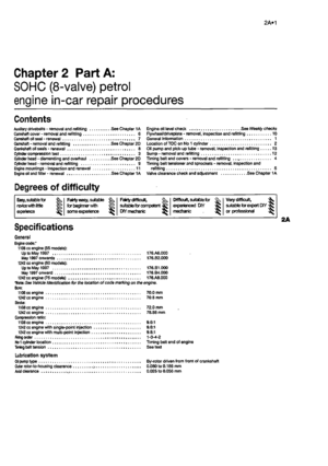 51
51 52
52 53
53 54
54 55
55 56
56 57
57 58
58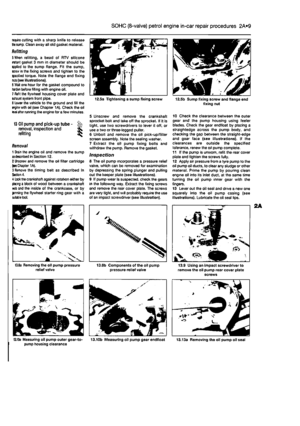 59
59 60
60 61
61 62
62 63
63 64
64 65
65 66
66 67
67 68
68 69
69 70
70 71
71 72
72 73
73 74
74 75
75 76
76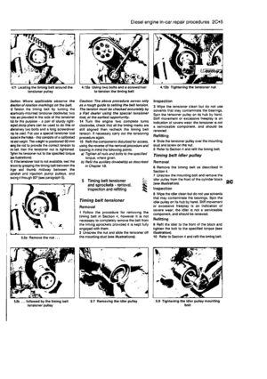 77
77 78
78 79
79 80
80 81
81 82
82 83
83 84
84 85
85 86
86 87
87 88
88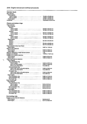 89
89 90
90 91
91 92
92 93
93 94
94 95
95 96
96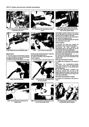 97
97 98
98 99
99 100
100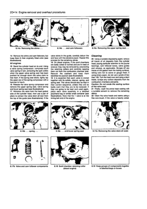 101
101 102
102 103
103 104
104 105
105 106
106 107
107 108
108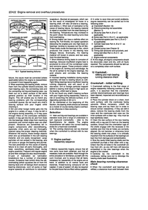 109
109 110
110 111
111 112
112 113
113 114
114 115
115 116
116 117
117 118
118 119
119 120
120 121
121 122
122 123
123 124
124 125
125 126
126 127
127 128
128 129
129 130
130 131
131 132
132 133
133 134
134 135
135 136
136 137
137 138
138 139
139 140
140 141
141 142
142 143
143 144
144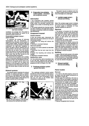 145
145 146
146 147
147 148
148 149
149 150
150 151
151 152
152 153
153 154
154 155
155 156
156 157
157 158
158 159
159 160
160 161
161 162
162 163
163 164
164 165
165 166
166 167
167 168
168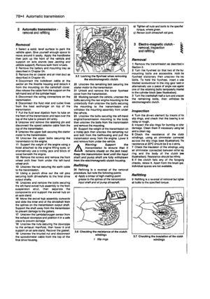 169
169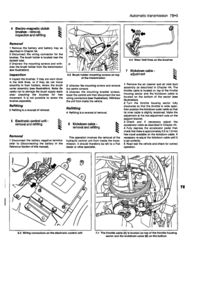 170
170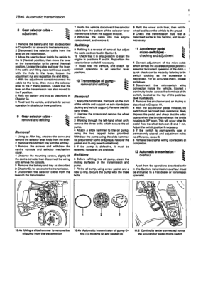 171
171 172
172 173
173 174
174 175
175 176
176 177
177 178
178 179
179 180
180 181
181 182
182 183
183 184
184 185
185 186
186 187
187 188
188 189
189 190
190 191
191 192
192 193
193 194
194 195
195 196
196 197
197 198
198 199
199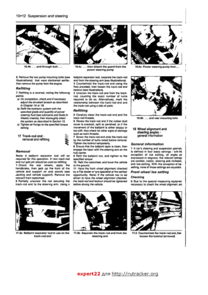 200
200 201
201 202
202 203
203 204
204 205
205 206
206 207
207 208
208 209
209 210
210 211
211 212
212 213
213 214
214 215
215 216
216 217
217 218
218 219
219 220
220 221
221 222
222 223
223 224
224