1993 VOLKSWAGEN CORRADO wheel torque
[x] Cancel search: wheel torquePage 743 of 920

STEERING COLUMN SWITCHES
Article Text (p. 8)
1993 Volkswagen Corrado
For Volkswagen Technical Site: http://vw.belcom.ru
Copyright © 1998 Mitchell Repair Information Company, LLC
Wednesday, March 22, 2000 09:23PM
Installation
1) To install, reverse removal procedure. Slide steering lock
housing onto steering column. Install contact ring, spring and
clamping washers onto steering column. Ensure proper operation of
steering lock and ignition switch.
NOTE: On Corrado SLC, pull steering column upward from steering
column tube as far as possible to ensure proper column
position.
2) Install combination switch, upper and lower steering
column covers and steering wheel. Tighten steering wheel nut to
specification. See TORQUE SPECIFICATIONS table.
TORQUE SPECIFICATIONS
TORQUE SPECIFICATIONS TABLEÄÄÄÄÄÄÄÄÄÄÄÄÄÄÄÄÄÄÄÄÄÄÄÄÄÄÄÄÄÄÄÄÄÄÄÄÄÄÄÄÄÄÄÄÄÄÄÄÄÄÄÄÄÄÄÄÄÄÄÄApplication Ft. Lbs. (N.m)
Steering Wheel Nut ................................. 30 (40)
INCH Lbs. (N.m)
Air Bag Unit-To-Steering Wheel Screws .............. 89 (10)
ÄÄÄÄÄÄÄÄÄÄÄÄÄÄÄÄÄÄÄÄÄÄÄÄÄÄÄÄÄÄÄÄÄÄÄÄÄÄÄÄÄÄÄÄÄÄÄÄÄÄÄÄÄÄÄÄÄÄÄÄEND OF ARTICLE
Page 747 of 920

STEERING GEAR - POWER RACK & PINION
Article Text (p. 4)
1993 Volkswagen Corrado
For Volkswagen Technical Site: http://vw.belcom.ru
Copyright © 1998 Mitchell Repair Information Company, LLC
Wednesday, March 22, 2000 09:23PM
Installation
To install, reverse removal procedure. Tighten nuts and bolts
to specification. See TORQUE SPECIFICATIONS table at end of article.
Fill and bleed hydraulic system. See HYDRAULIC SYSTEM BLEEDING. Check
wheel alignment. See WHEEL ALIGNMENT SPECIFICATIONS & PROCEDURES
article in the WHEEL ALIGNMENT section.
OVERHAUL
Manufacturer recommends that power steering pump and steering
gear be replaced, rather than be repaired.
TORQUE SPECIFICATIONS
TORQUE SPECIFICATIONS TABLEÄÄÄÄÄÄÄÄÄÄÄÄÄÄÄÄÄÄÄÄÄÄÄÄÄÄÄÄÄÄÄÄÄÄÄÄÄÄÄÄÄÄÄÄÄÄÄÄÄÄÄÄÄÄÄÄÄÄÄÄApplication Ft. Lbs. (N.m)
End Housing Bolt ................................. 37 (50)
Power Steering Pump Bolt ......................... 18 (25)
Pressure-Flow Limiting Valve Cap ................. 42 (57)
Pressure Line Fitting ............................ 29 (39)
Return Line Fitting
On Pump ........................................ 29 (39)
On Valve Housing ............................... 22 (30)
Steering Gear Retaining Bolt ..................... 24 (33)
Subframe Bolt
Long .......................................... 96 (130)
Short .......................................... 59 (80)
Tie Rod Lock Nut ................................. 42 (55)
Tie Rod-To-Steering Arm .......................... 32 (44)
Valve Housing Bolt ............................... 15 (20)
ÄÄÄÄÄÄÄÄÄÄÄÄÄÄÄÄÄÄÄÄÄÄÄÄÄÄÄÄÄÄÄÄÄÄÄÄÄÄÄÄÄÄÄÄÄÄÄÄÄÄÄÄÄÄÄÄÄÄÄÄEND OF ARTICLE
Page 756 of 920

SUSPENSION - FRONT
Article Text (p. 2)
1993 Volkswagen Corrado
For Volkswagen Technical Site: http://vw.belcom.ru
Copyright © 1998 Mitchell Repair Information Company, LLC
Wednesday, March 22, 2000 09:24PM
NOTE: See WHEEL ALIGNMENT SPECIFICATIONS & PROCEDURES article in
the WHEEL ALIGNMENT section.
WHEEL BEARING
No adjustment is required.
BALL JOINT CHECKING
Raise and support vehicle. Inspect ball joints for excessive
play and damaged rubber boots. There should be no vertical or
horizontal ball joint play. Replace ball joint if any play is present.
REMOVAL & INSTALLATION
HUB & KNUCKLE ASSEMBLY
Use exploded view illustration when removing or installing
hub and knuckle assembly. See Fig. 1.
LOWER CONTROL ARM & BALL JOINT
Removal
1) Raise and support vehicle. Remove bolt retaining ball
joint at steering knuckle. Separate ball joint from housing. Leave
control arm hanging in mounts at subframe.
2) If control arm is not to be removed and ball joint is
riveted to control arm, drill out ball joint rivets using a 9/32" (7
mm) drill. After drilling rivets, chisel off rivet heads (if
necessary). If ball joint is bolted to control arm, remove bolts.
Remove ball joint.
3) If control arm is to be removed from vehicle, remove
stabilizer bar link rod nut, washers, and bushings. Remove pivot bolt
and "U" bracket housing inner pivot pin. Slide out control arm.
NOTE: On vehicles with automatic transmission, engine may have to
be lifted slightly to gain access to pivot bolts.
Inspection
Check lower control arm bushings for excessive wear, cracks
or contamination. Replace bushings if necessary. To replace bushings,
press out worn bushing. Select new bushing and press into position.
Ensure bushing does not twist when seating into place.
Installation
Slide new ball joint into slot in control arm. Install and
tighten ball joint retaining bolts. Install lower control arm to
subframe. Install ball joint into steering knuckle. To complete
installation, reverse removal procedure. Tighten control arm bolts
with vehicle on ground. Tighten all bolts and nuts to specification.
See TORQUE SPECIFICATIONS table at end of article. Check wheel
Page 757 of 920

SUSPENSION - FRONT
Article Text (p. 3)
1993 Volkswagen Corrado
For Volkswagen Technical Site: http://vw.belcom.ru
Copyright © 1998 Mitchell Repair Information Company, LLC
Wednesday, March 22, 2000 09:24PM
alignment. See WHEEL ALIGNMENT SPECIFICATIONS & PROCEDURES article in
the WHEEL ALIGNMENT section.
STRUT ASSEMBLY
Removal
1) Raise and support vehicle. Remove wheel assembly.
Disconnect and wire caliper aside. Remove bolts retaining strut to
steering knuckle. Note top bolt is used for front wheel camber
adjustment.
2) Support front suspension arm and components. Pry
suspension strut from steering knuckle. Remove upper strut retaining
nuts from inside engine compartment. Remove strut assembly.
Installation
To install, reverse removal procedure. Tighten bolts and nuts
to specification. See TORQUE SPECIFICATIONS table at end of article.
Check wheel alignment. See WHEEL ALIGNMENT SPECIFICATIONS & PROCEDURES
article in the WHEEL ALIGNMENT section.
FRONT SUSPENSION ASSEMBLY
Removal
1) Raise and support vehicle at center with safety stands.
Disconnect brake line and plug openings. Leave flex line in place.
Remove stabilizer link rod nut, bushings and washers.
2) Remove tie rod nut. Separate tie rod from steering
knuckle. Disconnect inner portion of constant velocity joint from
transaxle drive flange.
3) Remove lower control arm front pivot bolt. Remove "U"
shaped bracket bolts at control arm rear pivot.
NOTE: On vehicles with automatic transmission, engine may have to
be lifted slightly to gain access to pivot bolts.
4) Support suspension assembly. Remove upper strut retaining
nuts. Remove suspension assembly from vehicle.
Installation
To install, reverse removal procedure. Ensure convex side of
thrust washer faces pivot bolt head. Tighten bolts and nuts to
specification. Check wheel alignment. Proceed to appropriate
WHEEL ALIGNMENT SPECIFICATIONS & PROCEDURES article in the WHEEL
ALIGNMENT section.
WHEEL BEARING
Removal
1) Remove axle shaft nut with front wheels on ground. Raise
and support vehicle. Allow suspension to hang free. Remove wheel
assembly. Remove brake caliper attaching bolts. Remove caliper and
wire aside. Remove brake disc retaining screw and remove disc.
Page 758 of 920
SUSPENSION - FRONT
Article Text (p. 4)
1993 Volkswagen Corrado
For Volkswagen Technical Site: http://vw.belcom.ru
Copyright © 1998 Mitchell Repair Information Company, LLC
Wednesday, March 22, 2000 09:24PM
2) Disconnect tie rod ball joint from steering knuckle.
Remove control arm ball joint clamp nut and bolt. Disconnect control
arm ball joint from steering knuckle. Remove steering knuckle.
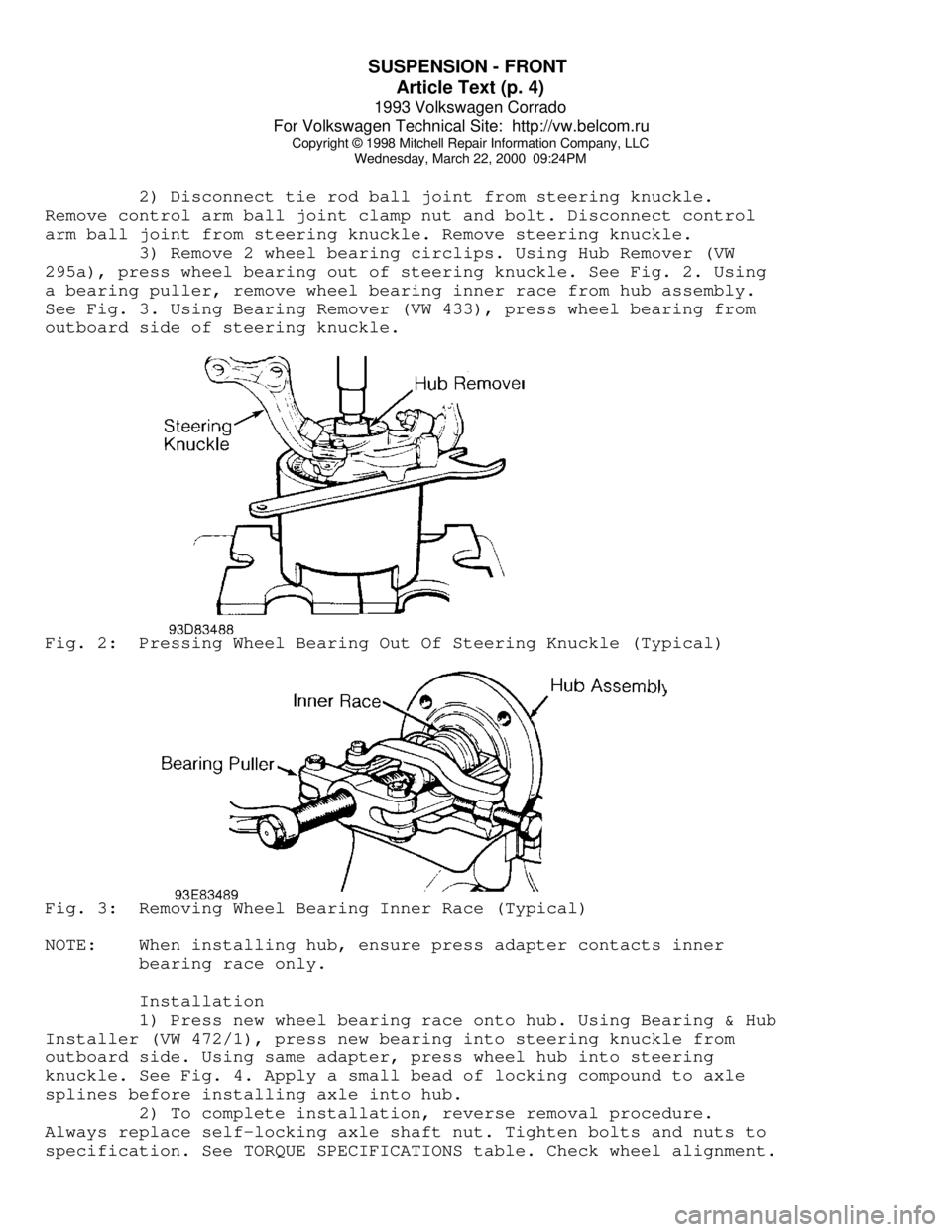
3) Remove 2 wheel bearing circlips. Using Hub Remover (VW
295a), press wheel bearing out of steering knuckle. See Fig. 2. Using
a bearing puller, remove wheel bearing inner race from hub assembly.
See Fig. 3. Using Bearing Remover (VW 433), press wheel bearing from
outboard side of steering knuckle.Fig. 2: Pressing Wheel Bearing Out Of Steering Knuckle (Typical)Fig. 3: Removing Wheel Bearing Inner Race (Typical)
NOTE: When installing hub, ensure press adapter contacts inner
bearing race only.
Installation
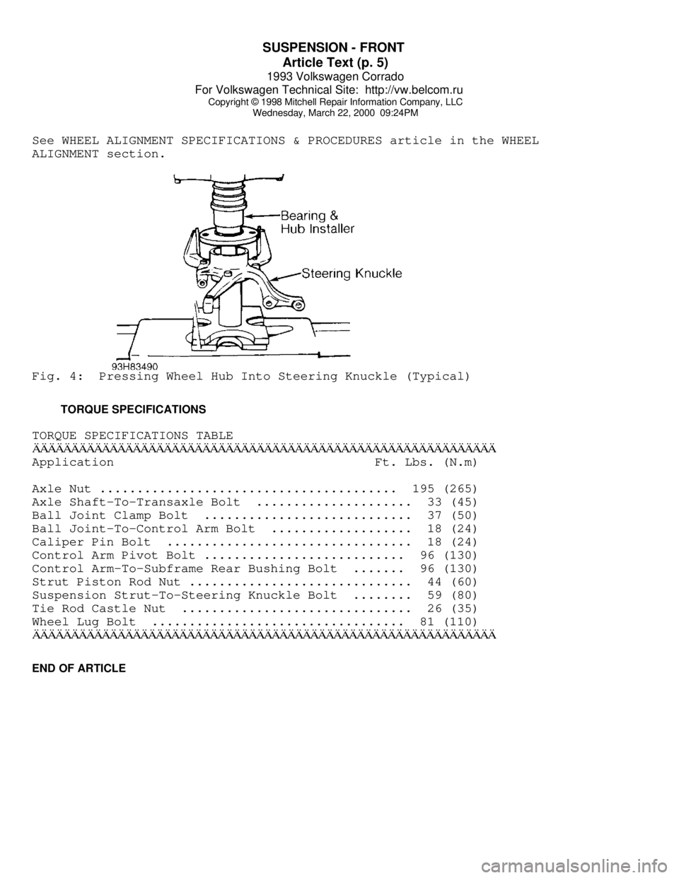
1) Press new wheel bearing race onto hub. Using Bearing & Hub
Installer (VW 472/1), press new bearing into steering knuckle from
outboard side. Using same adapter, press wheel hub into steering
knuckle. See Fig. 4. Apply a small bead of locking compound to axle
splines before installing axle into hub.
2) To complete installation, reverse removal procedure.
Always replace self-locking axle shaft nut. Tighten bolts and nuts to
specification. See TORQUE SPECIFICATIONS table. Check wheel alignment.
Page 759 of 920
SUSPENSION - FRONT
Article Text (p. 5)
1993 Volkswagen Corrado
For Volkswagen Technical Site: http://vw.belcom.ru
Copyright © 1998 Mitchell Repair Information Company, LLC
Wednesday, March 22, 2000 09:24PM
See WHEEL ALIGNMENT SPECIFICATIONS & PROCEDURES article in the WHEEL
ALIGNMENT section.Fig. 4: Pressing Wheel Hub Into Steering Knuckle (Typical)
TORQUE SPECIFICATIONS
TORQUE SPECIFICATIONS TABLEÄÄÄÄÄÄÄÄÄÄÄÄÄÄÄÄÄÄÄÄÄÄÄÄÄÄÄÄÄÄÄÄÄÄÄÄÄÄÄÄÄÄÄÄÄÄÄÄÄÄÄÄÄÄÄÄÄÄÄÄApplication Ft. Lbs. (N.m)
Axle Nut ........................................ 195 (265)
Axle Shaft-To-Transaxle Bolt ..................... 33 (45)
Ball Joint Clamp Bolt ............................ 37 (50)
Ball Joint-To-Control Arm Bolt ................... 18 (24)
Caliper Pin Bolt ................................. 18 (24)
Control Arm Pivot Bolt ........................... 96 (130)
Control Arm-To-Subframe Rear Bushing Bolt ....... 96 (130)
Strut Piston Rod Nut .............................. 44 (60)
Suspension Strut-To-Steering Knuckle Bolt ........ 59 (80)
Tie Rod Castle Nut ............................... 26 (35)
Wheel Lug Bolt .................................. 81 (110)
ÄÄÄÄÄÄÄÄÄÄÄÄÄÄÄÄÄÄÄÄÄÄÄÄÄÄÄÄÄÄÄÄÄÄÄÄÄÄÄÄÄÄÄÄÄÄÄÄÄÄÄÄÄÄÄÄÄÄÄÄEND OF ARTICLE
Page 766 of 920
VR65 ENGINE: AFFIX NEW VACUUM HOSE ROUTING LABEL
Article Text (p. 7)
1993 Volkswagen Corrado
For Volkswagen Technical Site: http://vw.belcom.ru
Copyright © 1998 Mitchell Repair Information Company, LLC
Wednesday, March 22, 2000 09:26PM
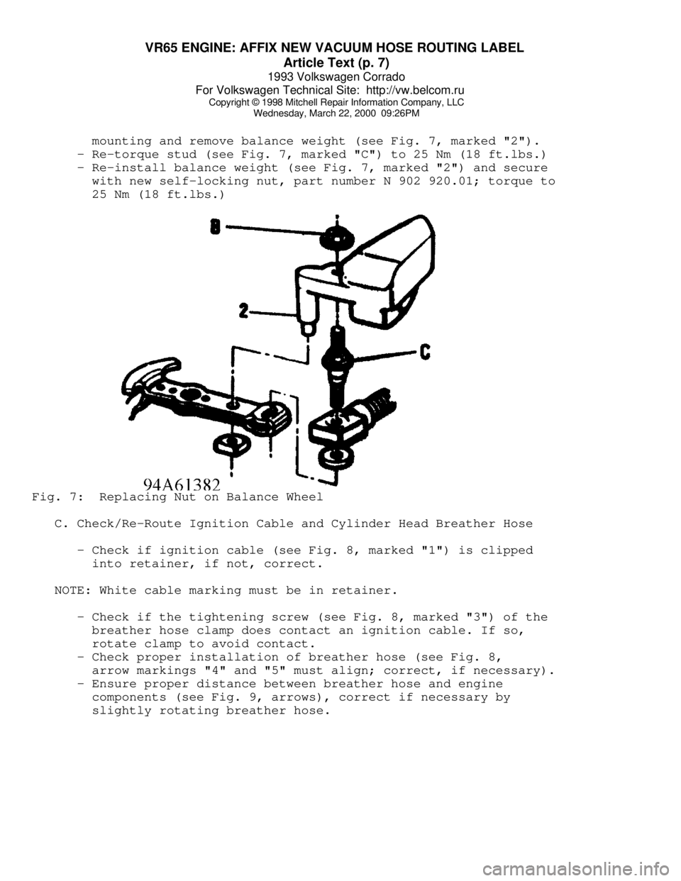
mounting and remove balance weight (see Fig. 7, marked "2").
- Re-torque stud (see Fig. 7, marked "C") to 25 Nm (18 ft.lbs.)
- Re-install balance weight (see Fig. 7, marked "2") and secure
with new self-locking nut, part number N 902 920.01; torque to
25 Nm (18 ft.lbs.)Fig. 7: Replacing Nut on Balance Wheel
C. Check/Re-Route Ignition Cable and Cylinder Head Breather Hose
- Check if ignition cable (see Fig. 8, marked "1") is clipped
into retainer, if not, correct.
NOTE: White cable marking must be in retainer.
- Check if the tightening screw (see Fig. 8, marked "3") of the
breather hose clamp does contact an ignition cable. If so,
rotate clamp to avoid contact.
- Check proper installation of breather hose (see Fig. 8,
arrow markings "4" and "5" must align; correct, if necessary).
- Ensure proper distance between breather hose and engine
components (see Fig. 9, arrows), correct if necessary by
slightly rotating breather hose.
Page 776 of 920

SUSPENSION - REAR
Article Text (p. 3)
1993 Volkswagen Corrado
For Volkswagen Technical Site: http://vw.belcom.ru
Copyright © 1998 Mitchell Repair Information Company, LLC
Wednesday, March 22, 2000 09:24PM
Removal
1) With vehicle on floor, remove plastic cap which covers
upper strut/shock retaining nuts. Remove strut/shock retaining nuts.
Slowly raise vehicle until weight is off spring. Remove bolt which
retains lower end of strut/shock absorber to axle beam mount. Raise
vehicle until strut/shock can be removed. Place strut/shock assembly
in vise.
2) Hold piston rod. Remove strut/shock retaining nut and
related components. See Fig. 1. Remove slotted nut (some models).
Remove spacer and coil spring. If coil spring is to be replaced,
ensure paint stripe color on replacement spring matches original
spring color stripe.
Installation
1) Install protective cap and tube onto shock absorber.
Install rubber buffer with small end downward. Install snap ring and
washer. Place spring into lower seat. Install upper retainer with
spacer sleeve.
2) Tighten slotted nut (some models) which retains piston
rod. Install upper mounting hardware. Tighten piston rod. To complete
installation, reverse removal procedure. Tighten bolts and nuts to
specification. See TORQUE SPECIFICATIONS table at end of article.
SUSPENSION ASSEMBLY
CAUTION: When removing suspension assembly, add weight to rear of
vehicle to prevent tipping due to change in center of
gravity.
Removal
1) With vehicle on floor, disconnect upper strut/shock mount.
Raise and support vehicle. Disconnect parking brake at bracket near
axle mount.
2) Disconnect and plug brakelines. Leave flex hose attached
to suspension. Separate brake pressure regulator spring from axle beam
(if equipped). Remove nuts which retain axle beam to body.
NOTE: DO NOT install bolts and nuts fouled with undercoating. With
waxy coating on threads, true tightening torque cannot be
measured. Clean or replace bolts and nuts.
Installation
1) If axle beam mounting has been removed, adjust mounting
pad. See Fig. 2. If pad is not correctly aligned, torsional preload of
mounting bushings will be incorrect.
2) Position rear suspension on body. Install nuts retaining
axle beam to body. Raise wheel. Guide upper end of strut/shock into
body mount.
3) Connect parking brake cables. Connect brakelines. Lower
vehicle. Tighten upper strut/shock retaining nuts. Tighten all bolts
and nuts to specification. Bleed brake system.