1993 VOLKSWAGEN CORRADO wheel torque
[x] Cancel search: wheel torquePage 449 of 920
CLUTCH
Article Text (p. 4)
1993 Volkswagen Corrado
For Volkswagen Technical Site: http://vw.belcom.ru
Copyright © 1998 Mitchell Repair Information Company, LLC
Wednesday, March 22, 2000 08:58PM
* Worn To Surface Of Rivet Heads
* Rivets Are Loose, Missing Or Damaged
* Friction Material Is Oil Or Grease Soaked
* Friction Material Is Loose, Cracked Or Grooved
* Hub Is Rusted Or Damaged
* Springs Are Rusted Solid, Broken, Cracked Or Loose
* Torsion Damper Spring Guide Is Broken
* Torsion Damper Cover Damaged
* Torsion Damper Grooved Or Not Functioning
NOTE: Pressure plate has a protective grease coating. Remove
contact surface grease only. Service life will be shortened
if remaining portions of pressure plate protective grease
are removed.
Installation
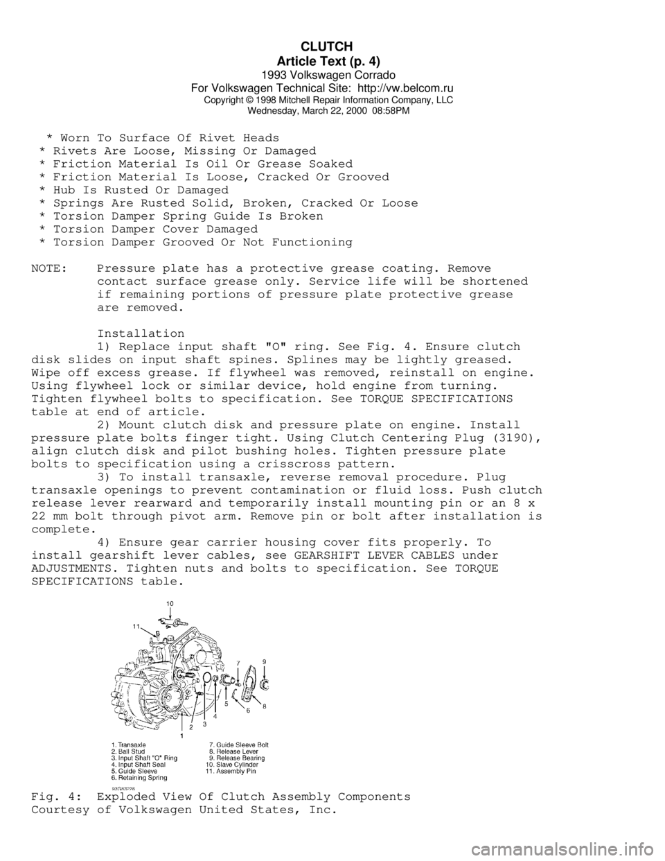
1) Replace input shaft "O" ring. See Fig. 4. Ensure clutch
disk slides on input shaft spines. Splines may be lightly greased.
Wipe off excess grease. If flywheel was removed, reinstall on engine.
Using flywheel lock or similar device, hold engine from turning.
Tighten flywheel bolts to specification. See TORQUE SPECIFICATIONS
table at end of article.
2) Mount clutch disk and pressure plate on engine. Install
pressure plate bolts finger tight. Using Clutch Centering Plug (3190),
align clutch disk and pilot bushing holes. Tighten pressure plate
bolts to specification using a crisscross pattern.
3) To install transaxle, reverse removal procedure. Plug
transaxle openings to prevent contamination or fluid loss. Push clutch
release lever rearward and temporarily install mounting pin or an 8 x
22 mm bolt through pivot arm. Remove pin or bolt after installation is
complete.
4) Ensure gear carrier housing cover fits properly. To
install gearshift lever cables, see GEARSHIFT LEVER CABLES under
ADJUSTMENTS. Tighten nuts and bolts to specification. See TORQUE
SPECIFICATIONS table.Fig. 4: Exploded View Of Clutch Assembly Components
Courtesy of Volkswagen United States, Inc.
Page 450 of 920

CLUTCH
Article Text (p. 5)
1993 Volkswagen Corrado
For Volkswagen Technical Site: http://vw.belcom.ru
Copyright © 1998 Mitchell Repair Information Company, LLC
Wednesday, March 22, 2000 08:58PM
TORQUE SPECIFICATIONS
TORQUE SPECIFICATIONS TABLEÄÄÄÄÄÄÄÄÄÄÄÄÄÄÄÄÄÄÄÄÄÄÄÄÄÄÄÄÄÄÄÄÄÄÄÄÄÄÄÄÄÄÄÄÄÄÄÄÄÄÄÄÄÄÄÄÄÄÄÄÄÄÄÄÄÄÄÄÄÄApplication Ft. Lbs. (N.m)
Balance Weight-To-Mount Bolt ............................... 22 (30)
Drive Axle-To-Flange Bolt .................................. 33 (45)
Flywheel Bolt ................................... 22 (30) + 1/4 Turn
Front Transaxle Mount Nut .................................. 44 (60)
Gearshift Cable Bolt ....................................... 18 (25)
Gearshift Cable Support Bolt ............................... 18 (25)
Left Transaxle Mount
Bracket-To-Mount Bolt ..................................... 44 (60)
Bracket-To-Transaxle Bolt ................................. 18 (25)
Pressure Plate Bolt ........................................ 15 (20)
Right Rear Transaxle Mount Bolt ............................ 18 (25)
Slave Cylinder Bolt ........................................ 18 (25)
Starter Bolt ............................................... 44 (60)
Transaxle Support-To-Transaxle Bolt ........................ 44 (60)
Transaxle-To-Engine Bolt ................................... 59 (80)
ÄÄÄÄÄÄÄÄÄÄÄÄÄÄÄÄÄÄÄÄÄÄÄÄÄÄÄÄÄÄÄÄÄÄÄÄÄÄÄÄÄÄÄÄÄÄÄÄÄÄÄÄÄÄÄÄÄÄÄÄÄÄÄÄÄÄÄÄÄÄEND OF ARTICLE
Page 611 of 920

HOW TO USE SYSTEM WIRING DIAGRAMS
Article Text (p. 8)
1993 Volkswagen Corrado
For Volkswagen Technical Site: http://vw.belcom.ru
Copyright © 1998 Mitchell Repair Information Company, LLC
Wednesday, March 22, 2000 09:11PM
Power Top Relay(s) ........................... Power Convertible Top
Powertrain Control Module ....................... Engine Performance
Analog Instrument Panels
Cruise Control Systems
Data Link Connectors
Generators & Regulators
Starters
Power Window Motors .................................. Power Windows
Power Window Relay(s) ................................ Power Windows
Radiator Fan Motor(s) ........................ Electric Cooling Fans
Radiator Fan Relay(s) ........................... Engine Performance
Electric Cooling Fans
Rainsense Module .............................. Wiper/Washer Systems
Raise Relay .................................. Power Convertible Top
Remote Anti-Theft Personality (RAP) Module ....... Anti-Theft System
Starters
Warning Systems
Seat Belt Pretensioners ................... Air Bag Restraint System
Seat Belt Retractor Solenoid .................... Passive Restraints
Seat Belt Switch .......................... Air Bag Restraint System
Passive Restraints
Shift Interlock Solenoid ................... Shift Interlock Systems
Shift Lock Actuator ........................ Shift Interlock Systems
Side Marker Lights ................................. Exterior Lights
SIR Coil Assembly (Clockspring) ........... Air Bag Restraint System
Slip Ring (Clockspring) ................... Air Bag Restraint System
Steering Column Switches
SRS Control Module ........................ Air Bag Restraint System
Starter Motor ............................................. Starters
Starter Interrupt Relay ................................... Starters
Starter Solenoid .......................................... Starters
Starter Relay ............................................. Starters
Steering Wheel Position Sensor .................... Anti-Lock Brakes
Stoplights ......................................... Exterior Lights
Stoplight Switch ................................ Engine Performance
Cruise Control Systems
Anti-Lock Brakes
Sun Roof ECU ........................................ Power Sun Roof
Sun Roof Motor ...................................... Power Sun Roof
Sun Roof Position Sensor ............................ Power Sun Roof
Taillights ......................................... Exterior Lights
Throttle Position (TP) Sensor ................... Engine Performance
Torque Converter Clutch Solenoid/Switch ......... Engine Performance
Traction Control Switch ........................... Anti-Lock Brakes
Trailer Tow Connector .............................. Exterior Lights
Trailer Tow Relay .................................. Exterior Lights
Transmission/Transaxle .......................... Engine Performance
Transmission Control Module (TCM) ............... Engine Performance
Starters
Transmission Range Sensor ................................. Starters
Back-Up Lights
Engine Performance
Page 681 of 920

PRE-ALIGNMENT CHECKS
Article Text
1993 Volkswagen Corrado
For Volkswagen Technical Site: http://vw.belcom.ru
Copyright © 1998 Mitchell Repair Information Company, LLC
Wednesday, March 22, 2000 09:21PM
ARTICLE BEGINNING
Wheel Alignment
PRE-ALIGNMENT INSPECTION PROCEDURES
PRE-ALIGNMENT CHECKS
Before making wheel alignment adjustment, perform the
following checks:
1) Tires should be equal in size and runout must not be
excessive. Tires and wheels should be in balance, and inflated to
manufacturer's specifications.
2) Wheel bearings must be properly adjusted. Steering linkage
and suspension must not have excessive looseness. Check for wear in
tie rod ends and ball joints.
3) Steering gear box must not have excessive play. Check and
adjust to manufacturer's specifications.
4) Vehicle must be at curb height with full fuel load and
spare tire in vehicle. No extra load should be on vehicle.
5) Vehicle must be level with floor and with suspension
settled. Jounce front and rear of vehicle several times and allow it
to settle to normal curb height.
6) If steering wheel is not centered with front wheels in
straight-ahead position, correct by shortening one tie rod adjusting
sleeve and lengthening opposite sleeve equal amounts.
7) Ensure wheel lug nuts are tightened to torque
specifications.
END OF ARTICLE
Page 735 of 920

STEERING COLUMN
Article Text (p. 4)
1993 Volkswagen Corrado
For Volkswagen Technical Site: http://vw.belcom.ru
Copyright © 1998 Mitchell Repair Information Company, LLC
Wednesday, March 22, 2000 09:23PM
notch with lower "U" joint slot. Install boot and damping grommet. Fit
steering box to frame while guiding pinion shaft into lower "U" joint.
2) Hand-tighten steering gear retaining nuts. Place wheels in
straight-ahead position. Align pinion shaft and "U" joint. Tighten
pinch bolt. Tighten steering gear retaining nuts. Connect gearshift
linkage. Check linkage for smooth operation.
TORQUE SPECIFICATIONS
TORQUE SPECIFICATIONS TABLEÄÄÄÄÄÄÄÄÄÄÄÄÄÄÄÄÄÄÄÄÄÄÄÄÄÄÄÄÄÄÄÄÄÄÄÄÄÄÄÄÄÄÄÄÄÄÄÄÄÄÄÄÄÄÄÄÄÄÄÄApplication Ft. Lbs. (N.m)
Pinch Bolt ....................................... 22 (30)
Steering Column-To-Instrument Panel
Retaining Bolt ................................. 15 (20)
Shear Bolt ........................................ (1)
Steering Gear Retaining Nut ...................... 22 (30)
Steering Wheel Nut ................................. 30 (40)
INCH Lbs. (N.m)
Air Bag Unit-To-Steering Wheel Screws .............. 89 (10)
(1) - Tighten until bolt head snaps off.
ÄÄÄÄÄÄÄÄÄÄÄÄÄÄÄÄÄÄÄÄÄÄÄÄÄÄÄÄÄÄÄÄÄÄÄÄÄÄÄÄÄÄÄÄÄÄÄÄÄÄÄÄÄÄÄÄÄÄÄÄEND OF ARTICLE
Page 740 of 920

STEERING COLUMN SWITCHES
Article Text (p. 5)
1993 Volkswagen Corrado
For Volkswagen Technical Site: http://vw.belcom.ru
Copyright © 1998 Mitchell Repair Information Company, LLC
Wednesday, March 22, 2000 09:23PM
1) Insert lock cylinder into steering lock housing. Insert
key into lock cylinder. Push lock cylinder fully into housing while
gently turning key.
2) Install combination switch and upper and lower steering
column covers. Install steering wheel and nut. Tighten steering wheel
nut to specification. See TORQUE SPECIFICATIONS table.Fig. 6: Drilling Steering Lock Housing
Courtesy of Volkswagen United States, Inc.
SPIRAL SPRING
Removal (Cabriolet)
Before proceeding, follow air bag service precautions. See
SERVICE PRECAUTIONS in AIR BAG RESTRAINT SYSTEM article in the
ACCESSORIES/SAFETY EQUIPMENT section. Remove steering wheel. See
STEERING WHEEL. Remove knee bar panel and steering column lower trim.
Disconnect 2-pin wiring connector (Green/Black and Green/Red wires) at
base of steering column. Remove 3 spiral spring retaining screws, and
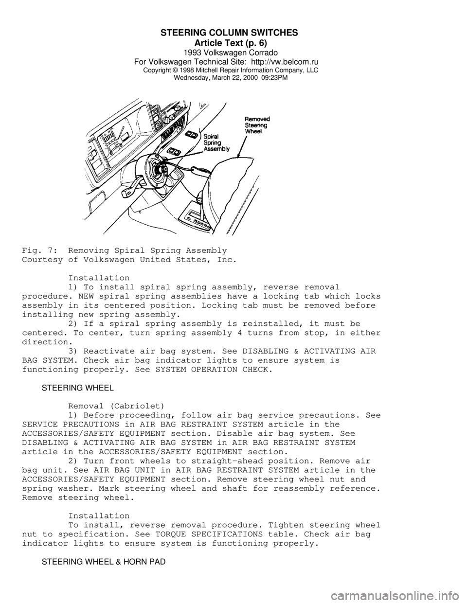
remove spiral spring. See Fig. 7.
Page 741 of 920
STEERING COLUMN SWITCHES
Article Text (p. 6)
1993 Volkswagen Corrado
For Volkswagen Technical Site: http://vw.belcom.ru
Copyright © 1998 Mitchell Repair Information Company, LLC
Wednesday, March 22, 2000 09:23PMFig. 7: Removing Spiral Spring Assembly
Courtesy of Volkswagen United States, Inc.
Installation
1) To install spiral spring assembly, reverse removal
procedure. NEW spiral spring assemblies have a locking tab which locks
assembly in its centered position. Locking tab must be removed before
installing new spring assembly.
2) If a spiral spring assembly is reinstalled, it must be
centered. To center, turn spring assembly 4 turns from stop, in either
direction.
3) Reactivate air bag system. See DISABLING & ACTIVATING AIR
BAG SYSTEM. Check air bag indicator lights to ensure system is
functioning properly. See SYSTEM OPERATION CHECK.
STEERING WHEEL
Removal (Cabriolet)
1) Before proceeding, follow air bag service precautions. See
SERVICE PRECAUTIONS in AIR BAG RESTRAINT SYSTEM article in the
ACCESSORIES/SAFETY EQUIPMENT section. Disable air bag system. See
DISABLING & ACTIVATING AIR BAG SYSTEM in AIR BAG RESTRAINT SYSTEM
article in the ACCESSORIES/SAFETY EQUIPMENT section.
2) Turn front wheels to straight-ahead position. Remove air
bag unit. See AIR BAG UNIT in AIR BAG RESTRAINT SYSTEM article in the
ACCESSORIES/SAFETY EQUIPMENT section. Remove steering wheel nut and
spring washer. Mark steering wheel and shaft for reassembly reference.
Remove steering wheel.
Installation
To install, reverse removal procedure. Tighten steering wheel
nut to specification. See TORQUE SPECIFICATIONS table. Check air bag
indicator lights to ensure system is functioning properly.
STEERING WHEEL & HORN PAD
Page 742 of 920
STEERING COLUMN SWITCHES
Article Text (p. 7)
1993 Volkswagen Corrado
For Volkswagen Technical Site: http://vw.belcom.ru
Copyright © 1998 Mitchell Repair Information Company, LLC
Wednesday, March 22, 2000 09:23PM
Removal (Except Cabriolet)
1) Disconnect negative battery cable. Remove screws attaching
horn button assembly/center pad to steering wheel from behind steering
wheel (if equipped).
2) Pull horn button assembly/center pad from steering wheel.
Use a cloth covered screwdriver to pry off horn button assembly/center
pad (if necessary). Disassemble horn button assembly (if necessary).
3) Place springs, contacts, horn or cruise control harness
connectors and screws in order for reassembly reference. Place wheels
in straight-ahead position.
4) Remove steering wheel retaining nut and washer. Mark
steering wheel and shaft for reassembly reference. Using a steering
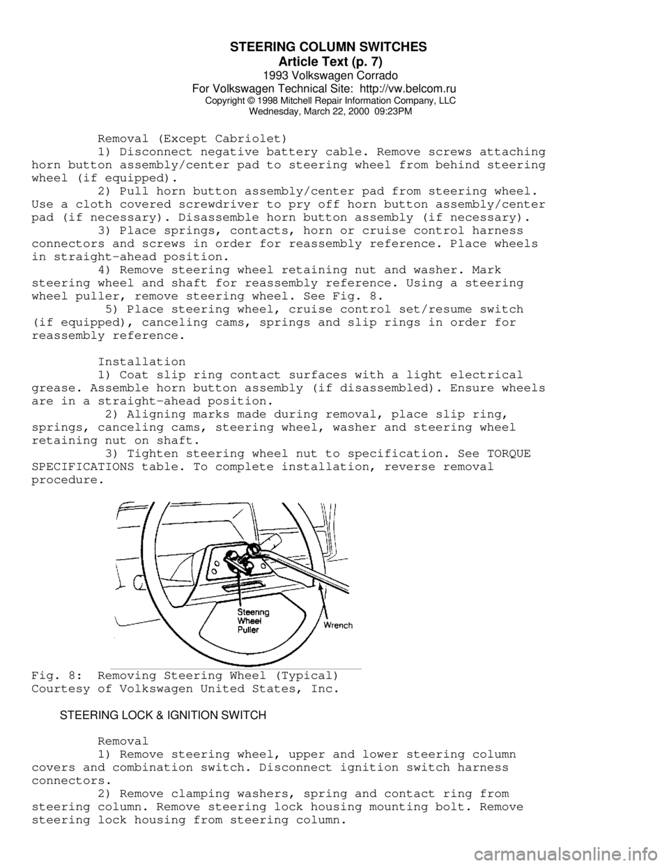
wheel puller, remove steering wheel. See Fig. 8.
5) Place steering wheel, cruise control set/resume switch
(if equipped), canceling cams, springs and slip rings in order for
reassembly reference.
Installation
1) Coat slip ring contact surfaces with a light electrical
grease. Assemble horn button assembly (if disassembled). Ensure wheels
are in a straight-ahead position.
2) Aligning marks made during removal, place slip ring,
springs, canceling cams, steering wheel, washer and steering wheel
retaining nut on shaft.
3) Tighten steering wheel nut to specification. See TORQUE
SPECIFICATIONS table. To complete installation, reverse removal
procedure.Fig. 8: Removing Steering Wheel (Typical)
Courtesy of Volkswagen United States, Inc.
STEERING LOCK & IGNITION SWITCH
Removal
1) Remove steering wheel, upper and lower steering column
covers and combination switch. Disconnect ignition switch harness
connectors.
2) Remove clamping washers, spring and contact ring from
steering column. Remove steering lock housing mounting bolt. Remove
steering lock housing from steering column.