1993 VOLKSWAGEN CORRADO light
[x] Cancel search: lightPage 719 of 920

SCHEDULED SERVICES
Article Text (p. 37)
1993 Volkswagen Corrado
For Volkswagen Technical Site: http://vw.belcom.ru
Copyright © 1998 Mitchell Repair Information Company, LLC
Wednesday, March 22, 2000 09:22PM³ 1.8L ......................................... 4.3 Qts. (4.0L) ³
³ 2.8L V6 ...................................... 6.3 Qts. (6.0L)
³
³
³
³ (1) - Capacities are recommended or calculated levels. Always use
³
³ dipstick (if available) to measure level.
³
³ (2) - Includes filter change.
³
ÀÄÄÄÄÄÄÄÄÄÄÄÄÄÄÄÄÄÄÄÄÄÄÄÄÄÄÄÄÄÄÄÄÄÄÄÄÄÄÄÄÄÄÄÄÄÄÄÄÄÄÄÄÄÄÄÄÄÄÄÄÄÄÄÄÄÄÄÄÙ 120,000 MILE (192,000 KM) SERVICE
120,000 MILE (192,000 KM) SERVICE
ÚÄÄÄÄÄÄÄÄÄÄÄÄÄÄÄÄÄÄÄÄÄÄÄÄÄÄÄÄÄÄÄÄÄÄÄÄÄÄÄÄÄÄÄÄÄÄÄÄÄÄÄÄÄÄÄÄÄÄÄÄÄÄÄÄÄÄÄÄ¿
³ Service Or Inspect
³
ÃÄÄÄÂÄÄÄÄÄÄÄÄÄÄÄÄÄÄÄÄÄÄÄÄÄÄÄÄÄÄÄÄÄÄÄÄÄÄÄÄÄÄÄÄÄÄÄÄÄÄÄÄÄÄÄÄÄÄÄÄÄÄÄÄÄÄÄÄ´
³
³ Verify Last Major Service Was Performed ³
ÃÄÄÄÅÄÄÄÄÄÄÄÄÄÄÄÄÄÄÄÄÄÄÄÄÄÄÄÄÄÄÄÄÄÄÄÄÄÄÄÄÄÄÄÄÄÄÄÄÄÄÄÄÄÄÄÄÄÄÄÄÄÄÄÄÄÄÄÄ´
³
³ Check On-Board Diagnostic Fault Memory (Purge if Required) ³
ÃÄÄÄÅÄÄÄÄÄÄÄÄÄÄÄÄÄÄÄÄÄÄÄÄÄÄÄÄÄÄÄÄÄÄÄÄÄÄÄÄÄÄÄÄÄÄÄÄÄÄÄÄÄÄÄÄÄÄÄÄÄÄÄÄÄÄÄÄ´
³
³ Check Fluid Levels ³
ÃÄÄÄÅÄÄÄÄÄÄÄÄÄÄÄÄÄÄÄÄÄÄÄÄÄÄÄÄÄÄÄÄÄÄÄÄÄÄÄÄÄÄÄÄÄÄÄÄÄÄÄÄÄÄÄÄÄÄÄÄÄÄÄÄÄÄÄÄ´
³
³ Check Cooling System Hoses and Clamps ³
ÃÄÄÄÅÄÄÄÄÄÄÄÄÄÄÄÄÄÄÄÄÄÄÄÄÄÄÄÄÄÄÄÄÄÄÄÄÄÄÄÄÄÄÄÄÄÄÄÄÄÄÄÄÄÄÄÄÄÄÄÄÄÄÄÄÄÄÄÄ´
³
³ Check Coolant Strength ³
ÃÄÄÄÅÄÄÄÄÄÄÄÄÄÄÄÄÄÄÄÄÄÄÄÄÄÄÄÄÄÄÄÄÄÄÄÄÄÄÄÄÄÄÄÄÄÄÄÄÄÄÄÄÄÄÄÄÄÄÄÄÄÄÄÄÄÄÄÄ´
³
³ Inspect For Fluid Leaks ³
ÃÄÄÄÅÄÄÄÄÄÄÄÄÄÄÄÄÄÄÄÄÄÄÄÄÄÄÄÄÄÄÄÄÄÄÄÄÄÄÄÄÄÄÄÄÄÄÄÄÄÄÄÄÄÄÄÄÄÄÄÄÄÄÄÄÄÄÄÄ´
³
³ Inspect/Adjust Accessory Drive Belts (Replace if Required) ³
ÃÄÄÄÅÄÄÄÄÄÄÄÄÄÄÄÄÄÄÄÄÄÄÄÄÄÄÄÄÄÄÄÄÄÄÄÄÄÄÄÄÄÄÄÄÄÄÄÄÄÄÄÄÄÄÄÄÄÄÄÄÄÄÄÄÄÄÄÄ´
³
³ A/C Cooling & Heating System ³
ÃÄÄÄÅÄÄÄÄÄÄÄÄÄÄÄÄÄÄÄÄÄÄÄÄÄÄÄÄÄÄÄÄÄÄÄÄÄÄÄÄÄÄÄÄÄÄÄÄÄÄÄÄÄÄÄÄÄÄÄÄÄÄÄÄÄÄÄÄ´
³
³ Crankcase Ventilation System ³
ÃÄÄÄÅÄÄÄÄÄÄÄÄÄÄÄÄÄÄÄÄÄÄÄÄÄÄÄÄÄÄÄÄÄÄÄÄÄÄÄÄÄÄÄÄÄÄÄÄÄÄÄÄÄÄÄÄÄÄÄÄÄÄÄÄÄÄÄÄ´
³
³ Intake Air System ³
ÃÄÄÄÅÄÄÄÄÄÄÄÄÄÄÄÄÄÄÄÄÄÄÄÄÄÄÄÄÄÄÄÄÄÄÄÄÄÄÄÄÄÄÄÄÄÄÄÄÄÄÄÄÄÄÄÄÄÄÄÄÄÄÄÄÄÄÄÄ´
³
³ Idle Speed ³
ÃÄÄÄÅÄÄÄÄÄÄÄÄÄÄÄÄÄÄÄÄÄÄÄÄÄÄÄÄÄÄÄÄÄÄÄÄÄÄÄÄÄÄÄÄÄÄÄÄÄÄÄÄÄÄÄÄÄÄÄÄÄÄÄÄÄÄÄÄ´
³
³ Inspect Brake System ³
ÃÄÄÄÅÄÄÄÄÄÄÄÄÄÄÄÄÄÄÄÄÄÄÄÄÄÄÄÄÄÄÄÄÄÄÄÄÄÄÄÄÄÄÄÄÄÄÄÄÄÄÄÄÄÄÄÄÄÄÄÄÄÄÄÄÄÄÄÄ´
³
³ Check Exhaust System & Heat Shielding ³
ÃÄÄÄÅÄÄÄÄÄÄÄÄÄÄÄÄÄÄÄÄÄÄÄÄÄÄÄÄÄÄÄÄÄÄÄÄÄÄÄÄÄÄÄÄÄÄÄÄÄÄÄÄÄÄÄÄÄÄÄÄÄÄÄÄÄÄÄÄ´
³
³ Clean Battery and Battery Terminals ³
ÃÄÄÄÅÄÄÄÄÄÄÄÄÄÄÄÄÄÄÄÄÄÄÄÄÄÄÄÄÄÄÄÄÄÄÄÄÄÄÄÄÄÄÄÄÄÄÄÄÄÄÄÄÄÄÄÄÄÄÄÄÄÄÄÄÄÄÄÄ´
³
³ Inspect Fuel/Tank/Cap/Lines ³
ÃÄÄÄÅÄÄÄÄÄÄÄÄÄÄÄÄÄÄÄÄÄÄÄÄÄÄÄÄÄÄÄÄÄÄÄÄÄÄÄÄÄÄÄÄÄÄÄÄÄÄÄÄÄÄÄÄÄÄÄÄÄÄÄÄÄÄÄÄ´
³
³ Check Operation of Horn, Wipers/Washers & All Exterior Lights ³
ÃÄÄÄÅÄÄÄÄÄÄÄÄÄÄÄÄÄÄÄÄÄÄÄÄÄÄÄÄÄÄÄÄÄÄÄÄÄÄÄÄÄÄÄÄÄÄÄÄÄÄÄÄÄÄÄÄÄÄÄÄÄÄÄÄÄÄÄÄ´
³
³ Inspect Condition of Wiper Blades ³
ÃÄÄÄÅÄÄÄÄÄÄÄÄÄÄÄÄÄÄÄÄÄÄÄÄÄÄÄÄÄÄÄÄÄÄÄÄÄÄÄÄÄÄÄÄÄÄÄÄÄÄÄÄÄÄÄÄÄÄÄÄÄÄÄÄÄÄÄÄ´
³
³ Check Headlight Alignment ³
ÃÄÄÄÅÄÄÄÄÄÄÄÄÄÄÄÄÄÄÄÄÄÄÄÄÄÄÄÄÄÄÄÄÄÄÄÄÄÄÄÄÄÄÄÄÄÄÄÄÄÄÄÄÄÄÄÄÄÄÄÄÄÄÄÄÄÄÄÄ´
³
³ Lubricate Weatherstripping with Silicone ³
ÃÄÄÄÅÄÄÄÄÄÄÄÄÄÄÄÄÄÄÄÄÄÄÄÄÄÄÄÄÄÄÄÄÄÄÄÄÄÄÄÄÄÄÄÄÄÄÄÄÄÄÄÄÄÄÄÄÄÄÄÄÄÄÄÄÄÄÄÄ´
Page 728 of 920

STARTER
Article Text (p. 2)
1993 Volkswagen Corrado
For Volkswagen Technical Site: http://vw.belcom.ru
Copyright © 1998 Mitchell Repair Information Company, LLC
Wednesday, March 22, 2000 09:23PM
Voltage reading should not be more than one volt less than battery
voltage. If a larger voltage drop is indicated, circuit between
battery and starter terminal may be defective.
Main Starter Case
Connect a voltmeter between positive battery terminal and
starter motor "M" terminal. With ignition off, operate starter for 2-3
seconds. Battery voltage should be present, then drop to less than one
volt. If voltage is greater than specification, high resistance may be
present in circuit. Go to ACROSS SOLENOID SWITCH test.
Across Solenoid Switch
Connect a voltmeter between 2 starter solenoid terminal stud
connections. With ignition disconnected, operate starter for 2-3
seconds and note meter reading. Initially, battery voltage should be
present, then voltage should drop to less than .5 volt. If voltage is
not as specified, check for damaged switch or loose or dirty
connections. If high resistance is present, terminal may be loose or
corroded.
Ground Return Line
Connect a voltmeter between battery ground terminal and
starter main housing. With ignition off, operate starter for 2-3
seconds. If ground is okay, voltage reading should be less than .5
volt. If reading is .6 volt or more, high resistance is present in
ground return side of circuit.
BENCH TESTING
STARTER SOLENOID
1) Remove bridge strap connecting solenoid to motor. Check
windings by connecting a 12-volt self-powered test light between
solenoid main terminal STA and solenoid body. If light illuminates,
both windings are satisfactory.
2) Ensure that contacts open and close satisfactorily by
connecting a 12-volt self-powered test light between starter solenoid
main terminals. Test light should not illuminate.
NOTE: Step 3) uses a non-powered (standard) test light.
3) Connect a test light to STARTER terminal of solenoid and
ground. Apply voltage to STA and BAT terminals of solenoid. Solenoid
should be heard to operate as contacts close and test light should
illuminate. When voltage is removed from STA terminal of solenoid,
test light should go out.
STARTER LOAD (LOCK) TEST
With starter on test bench, lock starter drive pinion.
Voltmeter should read 4.5 volts and ammeter should read 700-800 amps.
Page 741 of 920

STEERING COLUMN SWITCHES
Article Text (p. 6)
1993 Volkswagen Corrado
For Volkswagen Technical Site: http://vw.belcom.ru
Copyright © 1998 Mitchell Repair Information Company, LLC
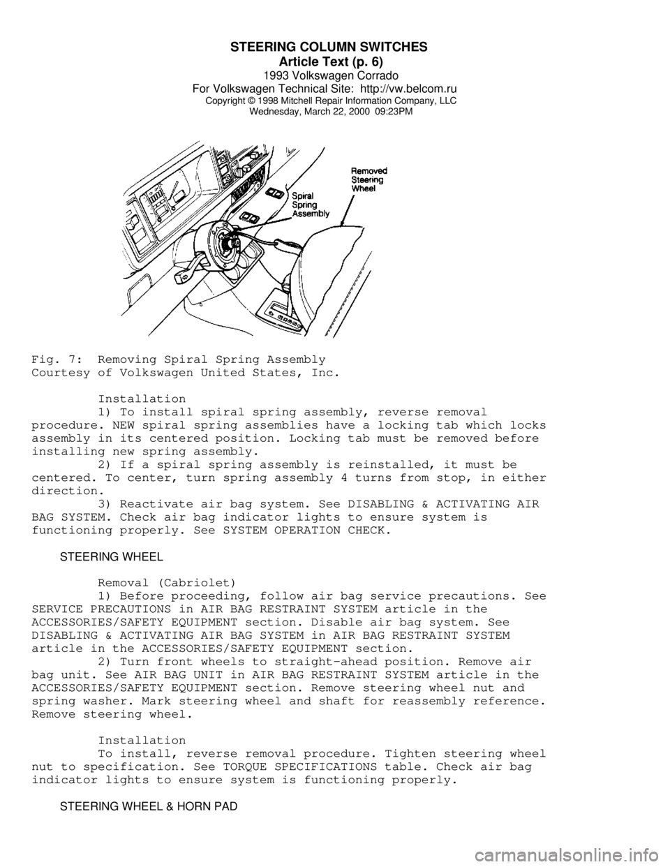
Wednesday, March 22, 2000 09:23PMFig. 7: Removing Spiral Spring Assembly
Courtesy of Volkswagen United States, Inc.
Installation
1) To install spiral spring assembly, reverse removal
procedure. NEW spiral spring assemblies have a locking tab which locks
assembly in its centered position. Locking tab must be removed before
installing new spring assembly.
2) If a spiral spring assembly is reinstalled, it must be
centered. To center, turn spring assembly 4 turns from stop, in either
direction.
3) Reactivate air bag system. See DISABLING & ACTIVATING AIR
BAG SYSTEM. Check air bag indicator lights to ensure system is
functioning properly. See SYSTEM OPERATION CHECK.
STEERING WHEEL
Removal (Cabriolet)
1) Before proceeding, follow air bag service precautions. See
SERVICE PRECAUTIONS in AIR BAG RESTRAINT SYSTEM article in the
ACCESSORIES/SAFETY EQUIPMENT section. Disable air bag system. See
DISABLING & ACTIVATING AIR BAG SYSTEM in AIR BAG RESTRAINT SYSTEM
article in the ACCESSORIES/SAFETY EQUIPMENT section.
2) Turn front wheels to straight-ahead position. Remove air
bag unit. See AIR BAG UNIT in AIR BAG RESTRAINT SYSTEM article in the
ACCESSORIES/SAFETY EQUIPMENT section. Remove steering wheel nut and
spring washer. Mark steering wheel and shaft for reassembly reference.
Remove steering wheel.
Installation
To install, reverse removal procedure. Tighten steering wheel
nut to specification. See TORQUE SPECIFICATIONS table. Check air bag
indicator lights to ensure system is functioning properly.
STEERING WHEEL & HORN PAD
Page 742 of 920

STEERING COLUMN SWITCHES
Article Text (p. 7)
1993 Volkswagen Corrado
For Volkswagen Technical Site: http://vw.belcom.ru
Copyright © 1998 Mitchell Repair Information Company, LLC
Wednesday, March 22, 2000 09:23PM
Removal (Except Cabriolet)
1) Disconnect negative battery cable. Remove screws attaching
horn button assembly/center pad to steering wheel from behind steering
wheel (if equipped).
2) Pull horn button assembly/center pad from steering wheel.
Use a cloth covered screwdriver to pry off horn button assembly/center
pad (if necessary). Disassemble horn button assembly (if necessary).
3) Place springs, contacts, horn or cruise control harness
connectors and screws in order for reassembly reference. Place wheels
in straight-ahead position.
4) Remove steering wheel retaining nut and washer. Mark
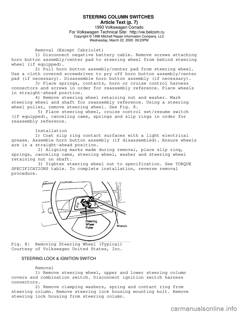
steering wheel and shaft for reassembly reference. Using a steering
wheel puller, remove steering wheel. See Fig. 8.
5) Place steering wheel, cruise control set/resume switch
(if equipped), canceling cams, springs and slip rings in order for
reassembly reference.
Installation
1) Coat slip ring contact surfaces with a light electrical
grease. Assemble horn button assembly (if disassembled). Ensure wheels
are in a straight-ahead position.
2) Aligning marks made during removal, place slip ring,
springs, canceling cams, steering wheel, washer and steering wheel
retaining nut on shaft.
3) Tighten steering wheel nut to specification. See TORQUE
SPECIFICATIONS table. To complete installation, reverse removal
procedure.Fig. 8: Removing Steering Wheel (Typical)
Courtesy of Volkswagen United States, Inc.
STEERING LOCK & IGNITION SWITCH
Removal
1) Remove steering wheel, upper and lower steering column
covers and combination switch. Disconnect ignition switch harness
connectors.
2) Remove clamping washers, spring and contact ring from
steering column. Remove steering lock housing mounting bolt. Remove
steering lock housing from steering column.
Page 748 of 920

SUN ROOF - POWER
Article Text
1993 Volkswagen Corrado
For Volkswagen Technical Site: http://vw.belcom.ru
Copyright © 1998 Mitchell Repair Information Company, LLC
Wednesday, March 22, 2000 09:23PM
ARTICLE BEGINNING
1993 ACCESSORIES & EQUIPMENT
Volkswagen Power Sun Roof
Volkswagen; Corrado SLC, EuroVan, Golf, GTI, Jetta, Passat
DESCRIPTION & OPERATION
The power sun roof operates at all times when the ignition is
in the on position. Power sun roof will operate after the ignition is
turned off until driver's door is opened. Power sun roof can also be
closed by inserting key in door lock and holding in the locked
position. If power system fails, sun roof can be operated manually by
removing control panel and rotating crank.
ADJUSTMENTS
NOTE: Adjustment information for EuroVan is not available.
PARALLEL ALIGNMENT
Corrado SLC, Golf, GTI, Jetta & Passat
1) Obtain radio code. Disconnect negative battery cable.
Using Headliner Trim Remover (3195), disengage headliner trim frame
from guide rails and push toward rear as far as possible. See Fig. 5
or 7.
2) Pry off interior light. Remove sun roof cable drive cover.
Remove cable drive mounting screws. Lower pinion drive until drive
pinion no longer meshes with cables.
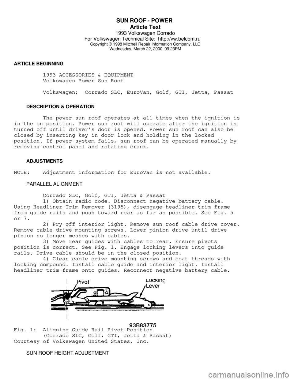
3) Move rear guides with cables to rear. Ensure pivots
position is correct. See Fig. 1. Engage locking levers into guide
rails. Drive cable should be in the closed position.
4) Clean cable drive mounting screws and coat threads with
locking compound. Install cable guide and interior light. Install
headliner trim frame onto guides. Reconnect negative battery cable.Fig. 1: Aligning Guide Rail Pivot Position
(Corrado SLC, Golf, GTI, Jetta & Passat)
Courtesy of Volkswagen United States, Inc.
SUN ROOF HEIGHT ADJUSTMENT
Page 756 of 920

SUSPENSION - FRONT
Article Text (p. 2)
1993 Volkswagen Corrado
For Volkswagen Technical Site: http://vw.belcom.ru
Copyright © 1998 Mitchell Repair Information Company, LLC
Wednesday, March 22, 2000 09:24PM
NOTE: See WHEEL ALIGNMENT SPECIFICATIONS & PROCEDURES article in
the WHEEL ALIGNMENT section.
WHEEL BEARING
No adjustment is required.
BALL JOINT CHECKING
Raise and support vehicle. Inspect ball joints for excessive
play and damaged rubber boots. There should be no vertical or
horizontal ball joint play. Replace ball joint if any play is present.
REMOVAL & INSTALLATION
HUB & KNUCKLE ASSEMBLY
Use exploded view illustration when removing or installing
hub and knuckle assembly. See Fig. 1.
LOWER CONTROL ARM & BALL JOINT
Removal
1) Raise and support vehicle. Remove bolt retaining ball
joint at steering knuckle. Separate ball joint from housing. Leave
control arm hanging in mounts at subframe.
2) If control arm is not to be removed and ball joint is
riveted to control arm, drill out ball joint rivets using a 9/32" (7
mm) drill. After drilling rivets, chisel off rivet heads (if
necessary). If ball joint is bolted to control arm, remove bolts.
Remove ball joint.
3) If control arm is to be removed from vehicle, remove
stabilizer bar link rod nut, washers, and bushings. Remove pivot bolt
and "U" bracket housing inner pivot pin. Slide out control arm.
NOTE: On vehicles with automatic transmission, engine may have to
be lifted slightly to gain access to pivot bolts.
Inspection
Check lower control arm bushings for excessive wear, cracks
or contamination. Replace bushings if necessary. To replace bushings,
press out worn bushing. Select new bushing and press into position.
Ensure bushing does not twist when seating into place.
Installation
Slide new ball joint into slot in control arm. Install and
tighten ball joint retaining bolts. Install lower control arm to
subframe. Install ball joint into steering knuckle. To complete
installation, reverse removal procedure. Tighten control arm bolts
with vehicle on ground. Tighten all bolts and nuts to specification.
See TORQUE SPECIFICATIONS table at end of article. Check wheel
Page 757 of 920

SUSPENSION - FRONT
Article Text (p. 3)
1993 Volkswagen Corrado
For Volkswagen Technical Site: http://vw.belcom.ru
Copyright © 1998 Mitchell Repair Information Company, LLC
Wednesday, March 22, 2000 09:24PM
alignment. See WHEEL ALIGNMENT SPECIFICATIONS & PROCEDURES article in
the WHEEL ALIGNMENT section.
STRUT ASSEMBLY
Removal
1) Raise and support vehicle. Remove wheel assembly.
Disconnect and wire caliper aside. Remove bolts retaining strut to
steering knuckle. Note top bolt is used for front wheel camber
adjustment.
2) Support front suspension arm and components. Pry
suspension strut from steering knuckle. Remove upper strut retaining
nuts from inside engine compartment. Remove strut assembly.
Installation
To install, reverse removal procedure. Tighten bolts and nuts
to specification. See TORQUE SPECIFICATIONS table at end of article.
Check wheel alignment. See WHEEL ALIGNMENT SPECIFICATIONS & PROCEDURES
article in the WHEEL ALIGNMENT section.
FRONT SUSPENSION ASSEMBLY
Removal
1) Raise and support vehicle at center with safety stands.
Disconnect brake line and plug openings. Leave flex line in place.
Remove stabilizer link rod nut, bushings and washers.
2) Remove tie rod nut. Separate tie rod from steering
knuckle. Disconnect inner portion of constant velocity joint from
transaxle drive flange.
3) Remove lower control arm front pivot bolt. Remove "U"
shaped bracket bolts at control arm rear pivot.
NOTE: On vehicles with automatic transmission, engine may have to
be lifted slightly to gain access to pivot bolts.
4) Support suspension assembly. Remove upper strut retaining
nuts. Remove suspension assembly from vehicle.
Installation
To install, reverse removal procedure. Ensure convex side of
thrust washer faces pivot bolt head. Tighten bolts and nuts to
specification. Check wheel alignment. Proceed to appropriate
WHEEL ALIGNMENT SPECIFICATIONS & PROCEDURES article in the WHEEL
ALIGNMENT section.
WHEEL BEARING
Removal
1) Remove axle shaft nut with front wheels on ground. Raise
and support vehicle. Allow suspension to hang free. Remove wheel
assembly. Remove brake caliper attaching bolts. Remove caliper and
wire aside. Remove brake disc retaining screw and remove disc.
Page 765 of 920

VR65 ENGINE: AFFIX NEW VACUUM HOSE ROUTING LABEL
Article Text (p. 6)
1993 Volkswagen Corrado
For Volkswagen Technical Site: http://vw.belcom.ru
Copyright © 1998 Mitchell Repair Information Company, LLC
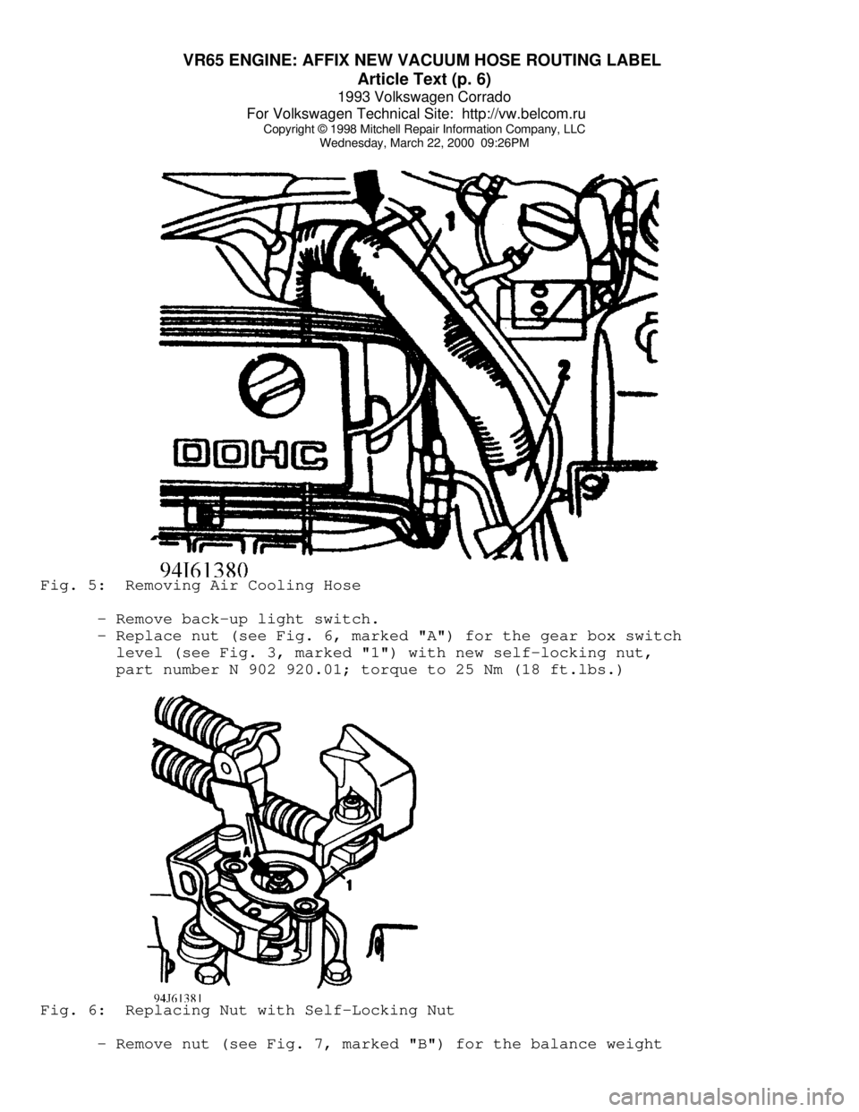
Wednesday, March 22, 2000 09:26PMFig. 5: Removing Air Cooling Hose
- Remove back-up light switch.
- Replace nut (see Fig. 6, marked "A") for the gear box switch
level (see Fig. 3, marked "1") with new self-locking nut,
part number N 902 920.01; torque to 25 Nm (18 ft.lbs.)Fig. 6: Replacing Nut with Self-Locking Nut
- Remove nut (see Fig. 7, marked "B") for the balance weight