Page 953 of 1254

OI$VEHICLE
SERVICE
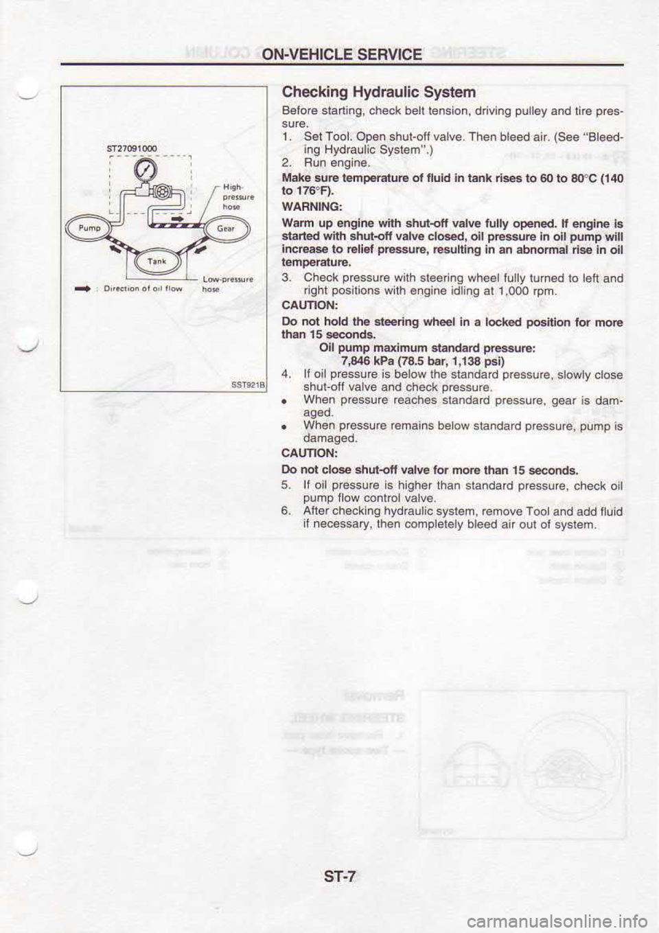
Checking Hydraulic System
Belo@ staning, check beft lension, d ving pul6yand
ri€ pr€s-
1. SelTool. Op€n.hutofivalve.
Then bleed air. (See
Beed-
ing HydElllc Systen".)
Mako sud tomp.EruB ol nuid in r.nk ds
to 60 to grc
fi lo
Wam up englne {ith shur{tt vdE lully oFned.
lt 4glre ls
slarted snh shur{fi vdE clG.d,
oll pEse
In olt plmp
yitl
incE.e ro Eliet pt!g@,
culing h an abtumd ds in dl
3. Cheok prcssurewith
3l€6rino wheelillly
luhed to bnand
fght posilions
wilh €nq n€ idlinq
al 1,000
lpm.
Do not hold th6 .l€.dng whel
ln a l@ked po€ilion
tor m@
oll p{mp
ndifrum d..d5d pe$uE:
7,046 kPa
{t85 bar,
1,133 p€D
4. It oi p.essure
is below lh6 slandard pressure,
slowlv close
shui-ofl @lve and check prassurc
. When p€ssurc
r€ach€s sl.ndad pGssure,
qear is dam,
. W'ea o e.sLE '€m:'n
slcndc d p
ess.r€. pump
's
Oo .ot do* shublt €lv6 ld m@ rh.n 15
seMds,
5 ll
oil pressurc
s higher than
standad pressure,
ch6ck oil
pump low conrrcl valve.
6. Aft6rch6ckln9 hydEulicsyslem,
redoveToo a.d add lluid
il n€cessary,
lhen @dplelely bleed an oul oi system
sT-7
Page 1134 of 1254
STARTING
SYSTEM _
Starter _
Dismantling (SR20DE,
GA1 6DE) (Cont'd)
REMOVE THE BRUSH PLATE
o By
means of a pliers,
move the end
@ of
the brush springs
Irom the rear lo the left side of the brush. This
is
to release
the brushes from pressure.
Repeat the same operation for
the rest
of brushes.
o Take
out the brush plate
assembly.
REMOVING THE FIELD COIL AND THE ARMATURE
o Withdraw
both the field
coil and the armature at the same
time.
(SMODE engine)
Take care not
to lose
the ball located
inside
the planeting
assembly. This ball is
for
bearing the armature end.
Dismantling gear
case
SR20DE engine
EL-23
Page 1160 of 1254

HEADLAMP
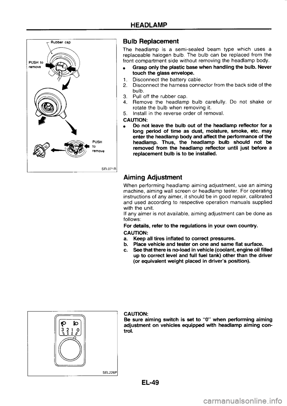
PUSH Io
\
_@. PUSH
lo Bulb
Replacement
The headlamp is
a semi-sealed beam type which
uses a
replaceable halogen
bulb. The
bulb can
be replaced from
the
f ront compartment side without
removing the headlamp
body.
r Grasp
only the plastic
base when
handling the bulb.
Never
touch the glass
envelope.
1. Disconnect the
battery cable.
2. Disconnect the
harness connector from
the back side ol the
bulb.
3. Pull
off the
rubber cap.
4. Remove the headlamp
bulb carefully. Do
not shake or
rotate the bulb when removing it.
5. Install
in the reverse
order of removal.
CAUTION:
o Do
not leave the bulb out of the headlamp
reflector for a
long period
of time as dust, moisture,
smoke, etc. may
enter the headlamp
body and aflect the pedormance
of the
headlamp. Thus, the headlamp
bulb should not
be
removed from
the headlamp reflector until just
before a
replac€ment bulb is
to be installed.
Aiming Adjustment
When performing
headlamp aiming adjustment, use
an aiming
machine, aiming wall screen or headlamp
lester. For
operating
instructions of any aimer, it should be in good
repair, calibrated
and used according to
respective operation manuals
supplied
with the unit.
lf any aimer is
not available, aiming adjustment can be done as
Iollows:
For details, reter
to the regulations in your
own country.
CAUTION:
a. Keep all tires inflated to correcl pressures.
b. Place vehicle
and tester on one
and same flat surface-
c. See that there
is noload in vehicle (coolant,
engine oil filled
up to correct level
and tull tuel tank) other than the driver
(or equivalent weight placed
in driver's position).
CAUTION: Be sure aiming switch
is set to "0"
when performing
aiming
adiustment on
vehicles equipped with
headlamp
aiming con-
trol.
lF-bl
l3 2
I 0l
L,\_-! S l l
,n
[) \/
EL-49
Page 1183 of 1254
METER
AND GAUGES
Oil Pressure
Switch Check
Check the continuity between the
terminals of oil pressure
switch and body ground.
Speedometer Cable Removal
and Installation
After disconnecting speedometer cable end from
transaxle,
push speedometer cable so that combination meter is pushed
into passenger
compartment. Disconnect speedometer cable
end from
combination meter
as shown in the frgure at left.
Speed Sensor Signal Check
e A
speed sensor
is built into the
speedometer.
1. Turn
speedometer slowly
using a small screwdriver.
2. Check continuity of speed sensor circuit.
Continuity exists two times for each turn ... O.K.
WTTHOUT TACHOMETEB
Wmi TACHOITIEIER More
lhan 10 -
20 (0.10 '
0.20,
0.1 -
0.2, 1.4 -
2.8)
Less than 10 -
20 (0.10 -
0.20,
0.1 -o.2,
1.4 -
2.4)
TO OTSCONNECT
sEL4l
EL-72
Page 1184 of 1254
WARNING
LAMPS AND BUZZER
Warning Lamps/Schematic
_s*_ ---
* ABsco
ioLL,.rrr
"5:_ f.
IrF -_l
# ts
Eac s:oNiRC- rNli
R! O
L'] @
BRAKE SEAT
8EL- L]N:
T
PARKI NG BRAKE SW: T'ts
ERArE FL!lt,
LE VEL SY! I TCts
OIL PRESSURE
SW: iTts
I,O:L LE !E.
!,NI'
C,l L LE /EL
ENGI NE O; L
LE! EL UNI T
:
c
c)a o
c.-^ o
a666 - -
g\11
=; :a I
=^l
: .l
rn
r:i
.n vi9
a-l]o .III
t; ',,
c G) 60"
9""
:3
c!EL.E,EL
I O ,l
.-- c+l
il L o!!
t -- ALTERNATOR
, FUEL LEVEL SWI -CH
FJE! FI
LIER sWI TCFI
crcvl or.rtr- t L urtt
viE
Ll CONIROL LrNl
I (EQ
T-t
-@F'.rcfr.rl
RH
LH
EL-73