Page 699 of 1254
E.G,R,
SYSTEM
Sch6malic Feler to outcK-GLow sYsTEir.
Wiring Diagram
Felef to olJtcK GLow sYsTEM.
De€crlplion
The F
G F
sysrem is d€srgnod ro
contrcr l.e .omation
o, NOr
emission by €circulalng
the exhaust gas
into th6 i.taka
man-
ilod psege
through lhe E.c.B. onrrot valve.
The enqne load
signal is
dot€ci€o wirh
lhe pol6ntion€r€r
insr.ned o. lhe '!el
ijecrion p-mp
cori@l laer. Tre e.g'ne
€eoluiion s€nsof lo€ted
on the oil pump
cov* pod!@s
the
Th€ E.G.R.
contol valve is aclivar€d by
lh€ vacuuh, g.n.€t€d
by rh€ vacuum pump.
E.G.R. @nrrclslenold
vatves aG us6d
lo conv€rl
lhe elecl @l signal fbm rha
contrcl devicg inlo a -
The E,G,B. syst6m is d€acrivated
when ihe wal6r lempeaturc
is low. The w.t€r lempehlue
sensor is oJ lh€ th6mi6tor
type
lhat d6l€cls lh€ r€mDeElure
ai th€ qlind€r
head.
EF & EC-398
Page 868 of 1254
REAR
AILE -
Ax|e Shaft (Rigid
Re€r Axle type)
Aesembly 1. Inslalloilcun€rin Ihe posito.
as shown in ittuslrsriona ert.
. M.k€
5!F oil 4l|er ii pchloned
pbpedy.
. Apply
muiipurpo* g|e@
lo sid. srlaca
2. Inslalrcmaining pans
io
B6arn9 spacer (Make
lldk€ 8uE rhdr
oll d grea$
srlae ol axle 3haft, bcadng axl€
shalt n
the lolowrng oder
sure chamiercde is lacng
axle
dc nor @me into
siact will
3 Posilion axe shafi 6ssmby
pans, menlionod above. onto
lo 44.1 KN (4lo
4.5lon,394 under
a p€ss
and press
al
axle shali al a load o139.2
el, coat sling lip with mltl-purD@
5. rn.elr
axle shaft assmby into
axte ese using
special
Removd Toolwhen
dislance'A b€lween
axte fiango ol
axr€ c.s6
beaing s 70,90 mm (2.76
!o 3.54 in).
RA.26
Page 869 of 1254
REAB
AXLE -
Arle Shaft (Rigid
Re€r Axle type)
Assembly (Cont'd)
6. Choos€ adiusijng sh ms lo
adiusl distance
"Oi beiveen
wh€€lb€ainq and axl6 hou6ing.
Di.r.ne '!D'
: 0 -
o.1 mm (0 -
0.004 In)
To c. culate d
stance D",
lse lor ow ng fomuta:
A -
Distanc6 benr€en nolch
oi beadnq and axte housing
Forselecling prcpefshim
thickn€$, r€ler to S DS
7 Check axiaLend play
ol dl€ shafi by !sng
a dialgauqe.
Alhle.d play:
0.1 mm (0.004
in) d l*3
It dlal @d play
i5 nol sithin 8p€ciferionB,
ep.at peedue
Ao @€tu| nor ro dEnEgE oil sl shen .dtustlng
dlat 6d
Ftay.
a, Connect pa*ing
b6ke cable and b6ke lube
9. Bleed an oul ol bhkino. rcuir.
AA-27
Page 1138 of 1254

STARTING
SYSTEM -
Starter -
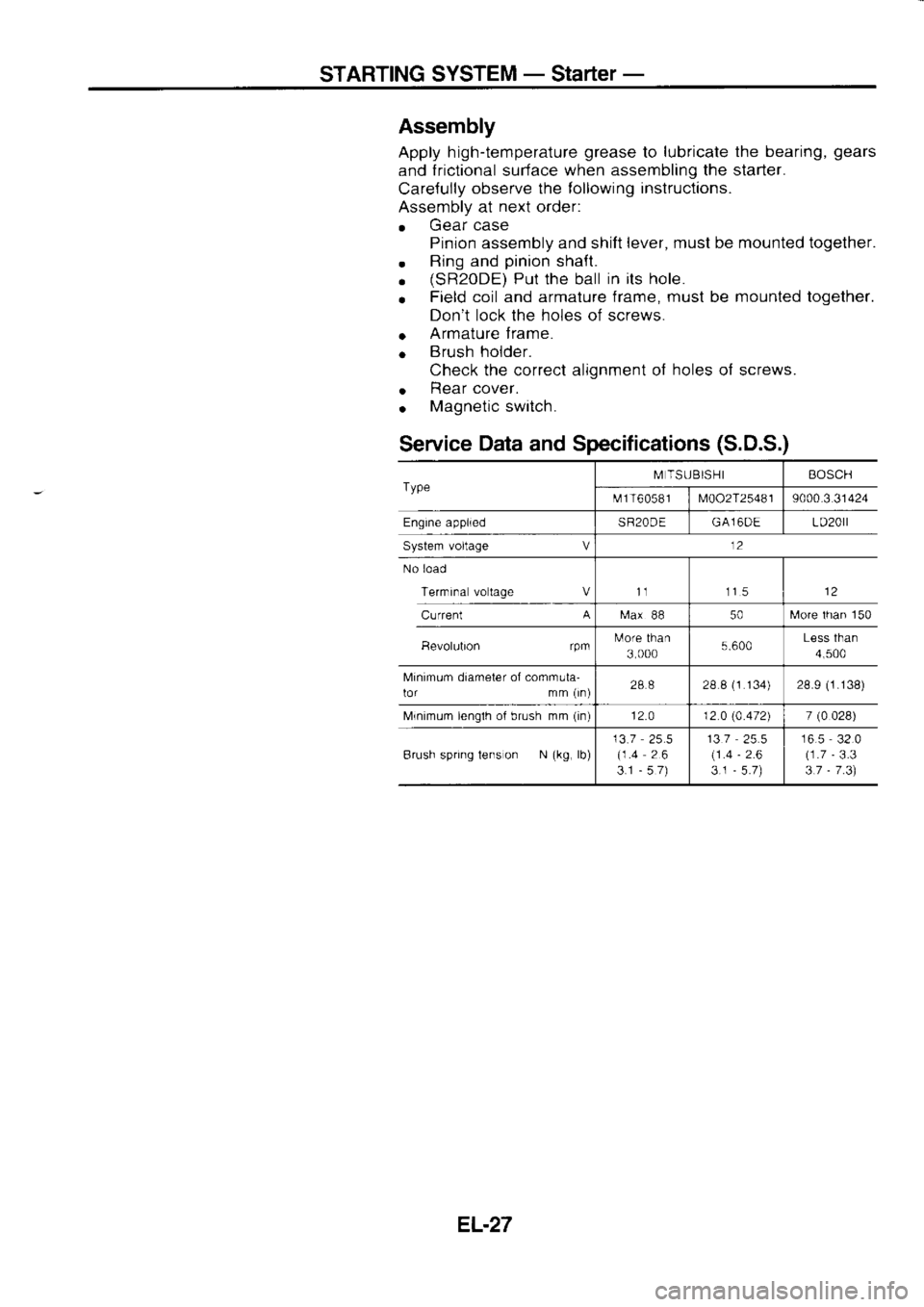
Assembly
Apply h igh-temperature grease
to lubricate
the bearing, gears
and frictional
surface when
assembling the starter.
Care{ully observe
the following inslructions.
Assembly at next
order:
. Gear
case
Pinion assembly and shift lever,
musl be mounted together.
. Ring
and pinion
shaft.
. (sR20DE)
Put the ball in
its hole.
o Field
coil and armature frame, must
be mounted
together.
Don't lock the holes of screws.
o Armature
f rame.
o Brush
holder.
Check the correct alignment of holes
of screws.
o Rear
cover.
. Magnetic
switch.
Service Data
and Specifications (S.D.S.)
Type M
TSUBISHI BOSCH
t\.rf 1 T6
05 8 I
M002T25481 9000.3
31424
Engine applied SR20DEGA16DE LD20rl
System voltage V 12
No load
Terrnrna voltage Vt1 115
Current A
[ra.x
88 50[,,lore
lhan 150
Bevolubon rpmtulore
than
3 000 5.600Less
than
4,500
Minimum diameter of comrnula-
lor mm (rn) 288
28 8 (1
134) 28.9 (1.138)
Mrnimum lenglh of brush mm (in)
12.0 12 0 (4.472)
7 (0
028)
Brush spring tens on N (kg,
lb) 13.7
25.5
(1.4 26
3.1 -57) 137
(1 .4
3.1 -
2.6 16.5
32.0
(1.7 -
3.3
3.7 -
7 .3)
EL.27
Page 1160 of 1254

HEADLAMP
PUSH Io
\
_@. PUSH
lo Bulb
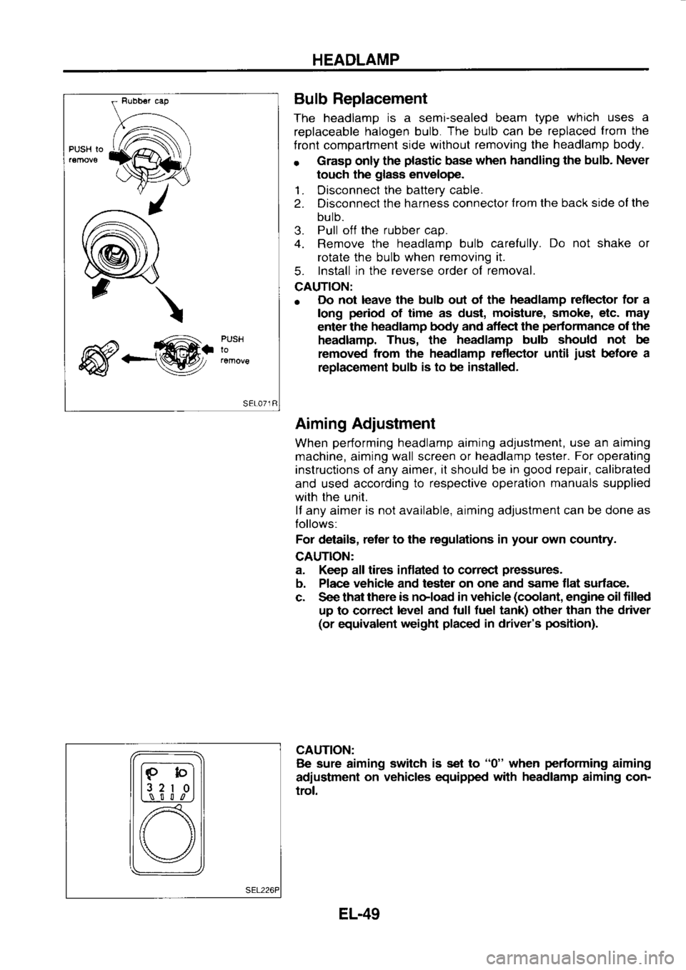
Replacement
The headlamp is
a semi-sealed beam type which
uses a
replaceable halogen
bulb. The
bulb can
be replaced from
the
f ront compartment side without
removing the headlamp
body.
r Grasp
only the plastic
base when
handling the bulb.
Never
touch the glass
envelope.
1. Disconnect the
battery cable.
2. Disconnect the
harness connector from
the back side ol the
bulb.
3. Pull
off the
rubber cap.
4. Remove the headlamp
bulb carefully. Do
not shake or
rotate the bulb when removing it.
5. Install
in the reverse
order of removal.
CAUTION:
o Do
not leave the bulb out of the headlamp
reflector for a
long period
of time as dust, moisture,
smoke, etc. may
enter the headlamp
body and aflect the pedormance
of the
headlamp. Thus, the headlamp
bulb should not
be
removed from
the headlamp reflector until just
before a
replac€ment bulb is
to be installed.
Aiming Adjustment
When performing
headlamp aiming adjustment, use
an aiming
machine, aiming wall screen or headlamp
lester. For
operating
instructions of any aimer, it should be in good
repair, calibrated
and used according to
respective operation manuals
supplied
with the unit.
lf any aimer is
not available, aiming adjustment can be done as
Iollows:
For details, reter
to the regulations in your
own country.
CAUTION:
a. Keep all tires inflated to correcl pressures.
b. Place vehicle
and tester on one
and same flat surface-
c. See that there
is noload in vehicle (coolant,
engine oil filled
up to correct level
and tull tuel tank) other than the driver
(or equivalent weight placed
in driver's position).
CAUTION: Be sure aiming switch
is set to "0"
when performing
aiming
adiustment on
vehicles equipped with
headlamp
aiming con-
trol.
lF-bl
l3 2
I 0l
L,\_-! S l l
,n
[) \/
EL-49
Page 1223 of 1254
HARNESS
LAYOUT
Main Harness -
L.H.D. Models
REAR SIDE
6rr)Y
nesistor @
lgnrlron coil---J4
\-f- E
C C.S controt unil
@ Dnvefs
side door switch (Type
A)
@ :
Rear solenord valve (SR2ODE
& LO2O
)
(D ro@
@ ro@
@ ro
-6D
@ :
Slide door
conneclor (s-door)
@ :To
@ (sR2oDE)
@! :
Driver s side
door swrtch (Type
B)
@ :
Radio condenser (SRmDE
I GA16OE)
@ :
Resislor (SR2ODE
A GAl6DE)
( .
Power transrstor
{SR2OOE 8 GA16DE)
@ lgn
rion
coil (Sn2ODE)
@ Air
flow
m€ter (SRmDE
& GA16DE)
@t Exhaust
gas
sensor (SR20DE)
@ gnrtron
coil (GA16DE)
EL-l12 MEL6188