Page 906 of 1254
ANI}LOCK
BRAKING
SYSTEM
System Components
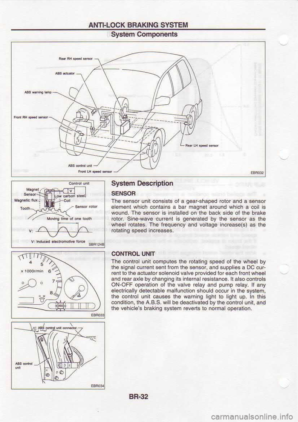
System Descriplion
SENSOF
Th6 sercof unil corcbb ol6 q€aFshgp.d
blor.nd a sensor
alamenl which
conlain6 a bar magnel
around which a coil is
wound. The sener is insialled on the back side ot lh6 b€k€
rotor. sin6'wav€ curent is g.neEted
by lhe sn.or a5 lhe
wh€€l rolale6.
Th. l@quency
and vollage inc€ase(s) as lhe
eialina speed inc€ases,
CONTBOL UNIT
Th. @ntrc! unit computes the oiating speed ol ihe wheet by
ihe siqnalcunentsenl fbn the *nsor, and supples a Dc cur
renl lo the a.iuaior solenoid valve provided
lor each lonr whe6l
and rear a e by cha.g ng its intemal resisla.€. ll also @ntrcl.
ON-OFF operaiion oi the valve rclay and pump
r6lay. ll any
6l6crric.lly d.reciable malluncrion
sholld odur in the system,
ihe contDl unir €uses the waning liqhr ro light up. In lhE
conditio., lhe A.B.S. wil be deaclival.d bv lh6 @ntrol
unt, and
the v6h cls s b€king sr€l€m r6v6ns
b noma
opeElion,
BR-32
Page 1112 of 1254
ELECTRICAL
SYSTEM
SECTION EL
When you
read wiring
diagrams:
o Read
Gl section, "HOW
TO READ WIRING
DIAGRAMS''.
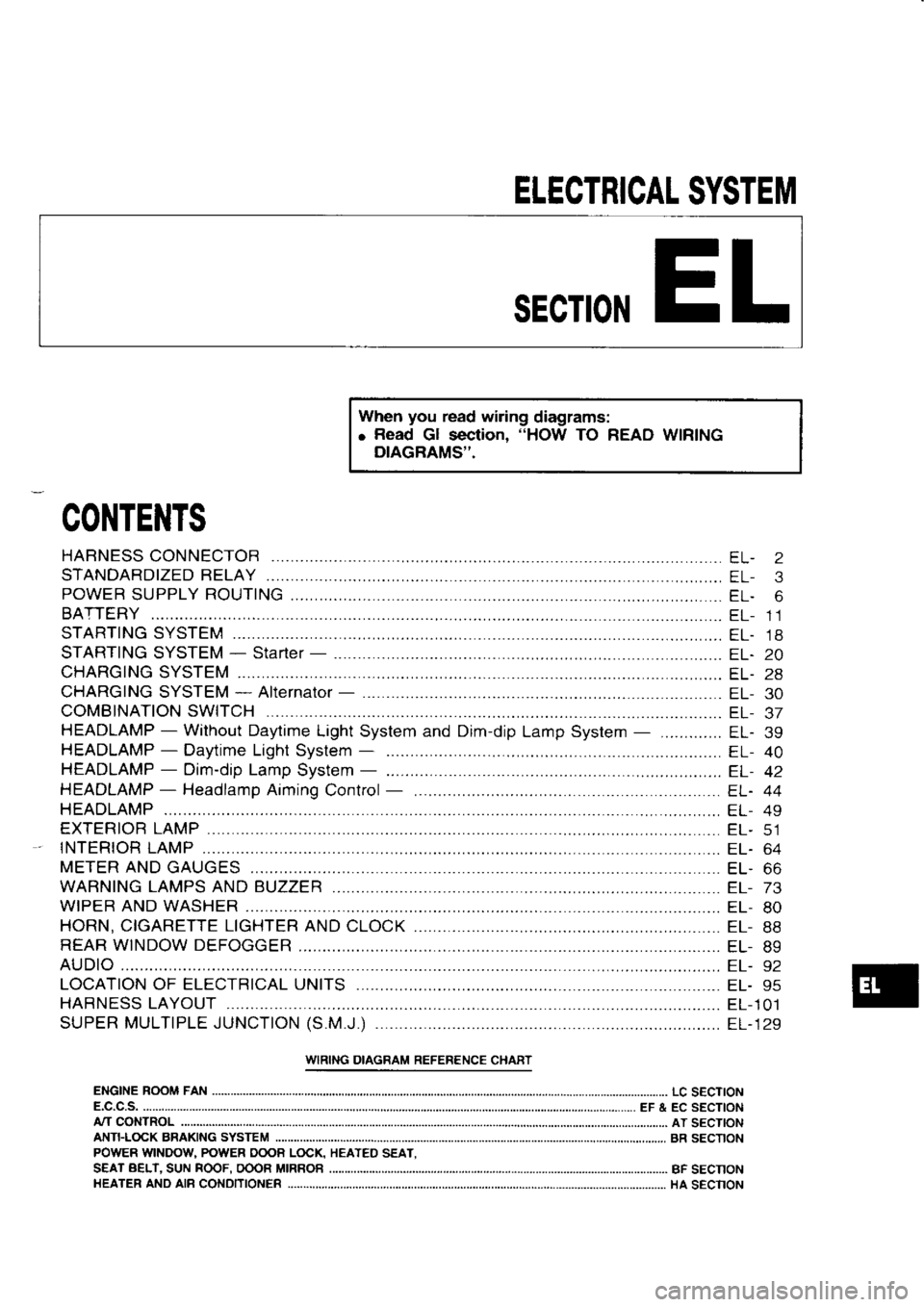
CONTENTS
STARTING SYSTEM
STARTING SYSTEM -
Starter -
...
CHARGING SYSTEM
CHARGING SYSTEM*
Alternator -
COMBINATION SWITCH ....
HEADLAMP -
Without Daytime Light System and Dim-dip
Lamp System
HEADLAMP -
Daytime Light
System -
HEADLAMP -
Dim-dip Lamp
System -
HEADLAMP -
Headlamp Aiming
Control
HEADLAMP
EXTERIOR LAMP ............
tNTER|OR 1AMP ............
METER AND
GAUGES
WARNING LAMPS AND BUZZER
WIPER AND WASHER
HORN, CIGARETTE LIGHTER AND
CLOCK
REAR WINDOW DEFOGGER EL-
2
EL- 3
EL- 6
EL- 11
EL. 18
EL.20
EL- 28
EL- 30
EL- J/
EL. 39
EL- 40
EL- 42
EL. 44
EL- 49
EL- CI
EL- 64
EL. OO
EL- 73
EL- 80
EL- 88
EL- 89
I::L- J Z
EL- 95
EL-101
EL- 129
LOCATION
OF ELECTRICAL UNITS
HARNESS LAYOUT ...,........
SUPER MULTIPLE JUNCTION (S.M.J.)
..........
URING DIAGRAM REFERENCE CHART
ENGINE ROOM FAN
LC S€CTION
E.C.C.S. EF & EC SECTION
ANTFLOCK BRAKING SYSTEM
A/T
CONTROL AT SECTION
BR SECTION
BF SECNON
HA SECNON
POWER
WINDOU POWER OOOB LOCK,
S€AT BELT.
SUN ROOF.
OOOR MIRROB
HEATER ANO AIB
CONDITIONER HEATED
SEAT.
Page 1148 of 1254
COMBINATION
SWITCH
Combination Switch/Check
REAR WIPER
AND WASHER
-wrpEa
TURN
a; --r
Lf o"fr
WASH
& WIPE
OFF
tINT
t LO
I Ht /
u
e 1ST
^ t\
OFF ,
LIGHT FNONT WIPER
AND WASHEF
FRONT WIPER AND
WASHER SWITCH a]
I ii
,6iGT,
.td
tq-Tfll
REAR WIPER AND
WASHER SWITCH til
l-l
l, L6le L,rtr I
Lrghtrng and
rurn srgnal
HORN SWITCH
TURN
SIGNAL
swtTcH
NmNn
llo ol
f2TdTm
ETT r0l
I
l-1
tGt
INTERMITTENT
wlPEF VOLUME in,A
ll
tl { \\1t F
-r- // L
\-:=/
;*-a o a-Lj
PER
OFF
I NT
I]I GH WIPE
OFFWIPE
LIGHTING SWITCH
EL-37
Page 1202 of 1254
REAR
WINDOW DEFOGGER
Orawrng pen Filament
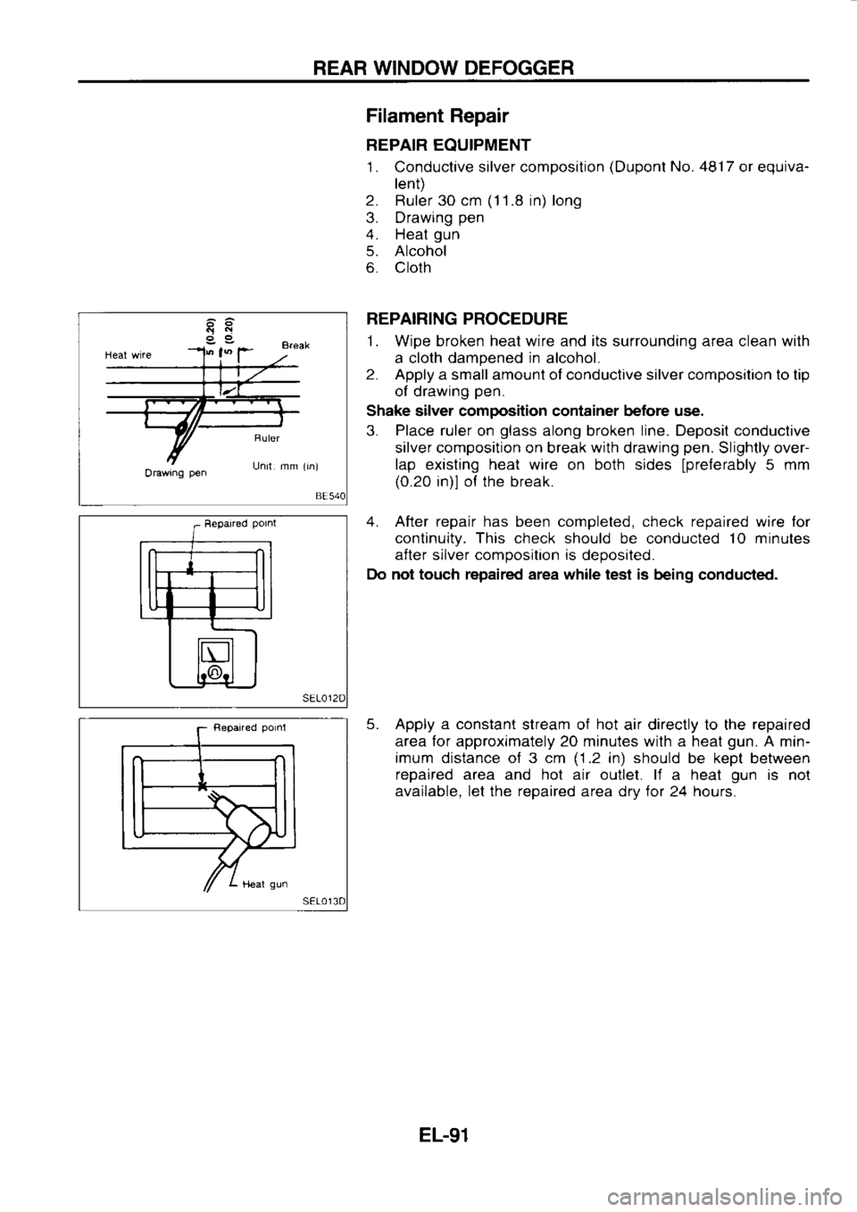
Repair
REPAIR EQUIPMENT
1. Conductive silver composition (Dupont
No. 48'17
or equiva-
lent)
2. Ruler 30 cm (1
1 .8 in) long
3. Drawing pen
4. Heat gun
5. Alcohol
6. Cloth
REPAIRING PROCEDURE
1. Wipe broken heat wire and its surrounding area clean with
a cloth dampened
in
alcohol.
2. Apply
a small amount of conductive silver composition to tip
ol drawing pen.
Shake silver composition container before use.
3. Place
ruler
on glass
along broken line. Deposil conductive
silver composition on break with drawing pen.
Slightly over-
lap existing heat wire
on both sides
lprelerably 5
mm
(0.20 in)l ol the break.
4. After repair has been completed, check repaired wire lor
continuity. This check
should be conducted 10
minutes
after silver composition
is
deposited.
Do not touch repaired area while test is
being conduc{ed.
5. Apply a constant
stream of hot
air directly to the repaired
area for approximately 20 minutes with a heat gun.
A min-
imum distance of 3 cm (1.2
in) should
be kept
between
repaired area and hot air outlet. li
a heat gun
is not
available. let the repaired
area drv for
24 hours.
EL-91