Page 673 of 1254

INJECTION
PUMP
Testing ol Inieclion
Pump (Conl'd)
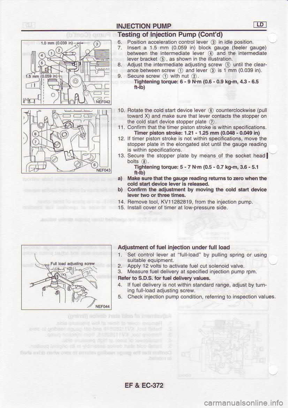
6. Position a@e eralion @nlrol lever
O in
idle posilion.
7. Insen a 1.5 dm (0.0ss
in) bl6k
sauqe (leeler
sauae)
beiveen lhe inlemediale lever
o and
lhe inlemediate
l.vff backol
O, 6
shown in the i lu$raton.
3. Adtusr ft€ inl€mod.le sdjusling scr6w
O untillh.
cl€ar
an@ belween screw
O and
lever
@ is
1 mn (0039 in)
L secure scrcw
O wllh
nul
@.
'ligbni.g
loqB:6 -I
N m (0.6 -
(I9
kg-h,43- 6,5
lr.rb)
Roialelh6 cold $an d€vi.e l.v.f
@ @unl.rclockw
s6 (pull
lowad X) and nake suE lhal lever @ntacts lhe slopper on
rhe cold sian devi@ stopper prate
o .
confim thal the iimer oislon slroke is wilhin soec li€ ons.
'lin* pi.td 3trok€: 121 -
125 mn (0044 -
ooag in)
It limd
Dislon stok€
s nol wllhin sD€.iii€lions. mov€ rh6
sropp€r plal6
in th6 elongar€d sbr
un l
th6 gauge
@ading
fi is
wilh n
specit€tons.
-3. Sec-re ll-e lroppe' pdle
by mears ol te soc*l l-.sdl
tlghtenlng rorq@: 5 -
7 N.n (05 -
oJ kg-n, 3.6 -
5,i
ff.tb)
.) Md6.u6 that th. gaug€
EEdlng Etuma lo EE vh.n OF
6ld d.rt dwi6 Lwr b ElEs€d.
b) Confim rh€.dF.tmr* by tlwlnq ih6 @ld
6t rt
dsle
l€Er lwo d ihm dma
14. Remove too, XVl12a2A19, ircm ihe lnjecton pump.
15. lfsiallcover otiimer at low prcssuGside.
AdlGtnsnt ol luel Inl€ctron
un(br lull
lo€d
1 Sel conlrol ev€r al lul-oad by pulling
sp ng or lslng
2. Apply 12
volE lo €clival€ rr€
cursol€noid valv€
3. l'r.asu€ lu€ld€livsry at sp€ciled ini€clion plmp
rpm.
8€16r to S,D.s. ld tu61 d€livsy v.l@.
4. lllu6ldeiveryis nolwithin standad
E.ge. adiu6l by tum-
ing lu l-
oad adlusling s.€w.
5. Ch€.k injeclion pump
condilon. relering
lo ln6p€clion
values.
EF & EC-372
Page 676 of 1254

INJECTION
PUMP
l9 lnstallation
(Cont'd)
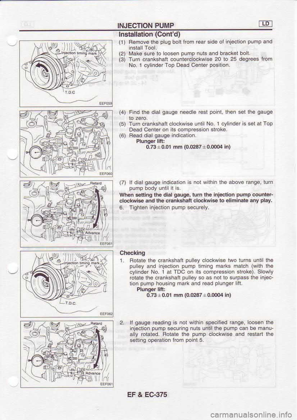
(1) F€mov6lhe plug
bol lrom ear sid€
of inl€cllon pump
a.d
(2) Mak€ suf€ to loosen pump
nuls and tack€l boll.
(3) Tum chnkstuft counlercLookwise
20 to 25
das@s lrom
No.I cylinder Top
D€ad C€nler positon.
(4) Fi.d th€ dial
aauq€ needle
Gsl poi.l,
then sel lha gauqe
Checklng i. Rolare lhe cdnkshan puley
clockwise lwo llhs
untllh6
pul€y and injeclion pudp
limng malks maLh (with
lh€
cyindd No. 1 al TDC on ils @mpression stbk€).
slowly
'orrle ihe .rarishal pLlley
so a
ton pump
housing ma* and read p
ungei in.
0,23+o01 mm (0.02&
+ 0.(xx)4 in)
2. ll galg€
reading is not within speciied range,
l@sen the
inj€ct on pump
secuing nuls udil$e pump
can be manu-
atly rotated. Roiat€
lh€ pump
clockwise and rcslan the
seft ng ope€lLon lrom poinl5.
(6)
Tun
cankshan cbokwlse unlilNo.1 cylinderis
setalTop
Dead Cenlefon ns codpresslor sltok€.
F€ad dial gauge
ind €to..
0.73*0,01 nn (Om87+oIXXX
In)
(7) ll dial gauge
indicalio. is nol within lhe above Enge, tun
pump body unllLit is
When s4ltlng lhe di.l gaug€,
turn rh€ injeclion punp
@nleF
d@kwilF and the @nlsh.lt d@kwi* lo
€liminata any play,
6. Tighten i.je.lion pump
5*!r€y.
)/t'r.
ffi;f
{ \}N K
t:
EF & EG375
Page 678 of 1254

INJECTION
PUMP
n11 I
r\|ji Adiuslmed
(Cont'd)
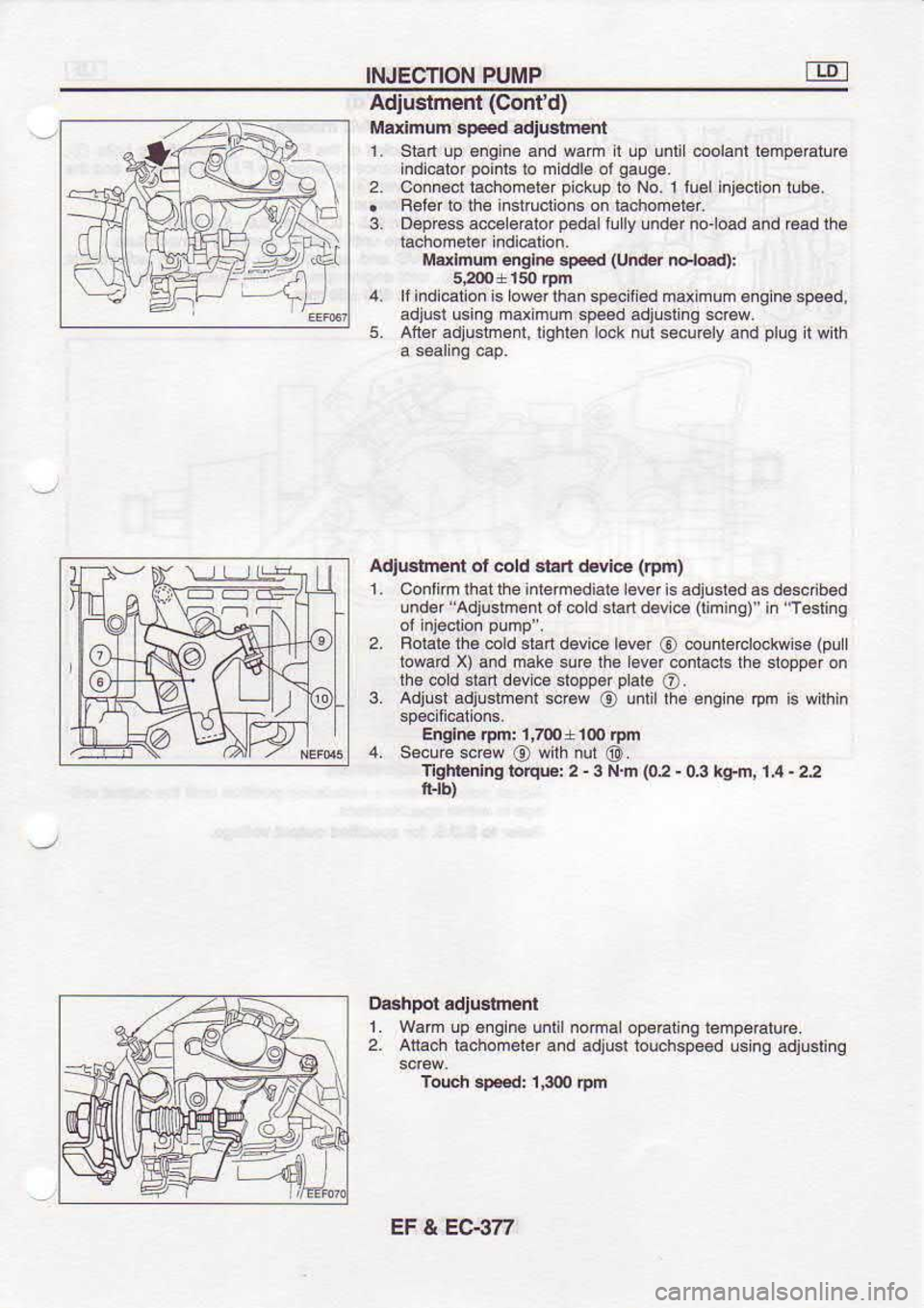
Marimum sP.€d adjtlgiment
1. Stan !p 6ngin€ and wam I !p unli oolanl l€mp€Etura
indi.alor poinb
lo mddl6 ol gaug6.
Connecr rachomerer pi.kup
ro No l
luelinjectonl!be.
Feter to the irstructions on taohoneter.
D€prcss accoloalor p€dalillly
und6r noload and €ad
the
Mdlmum englE sped (Under
Fl@d):
4. laindielion s owerlhan spocifod maximum efg nesp€€d,
adjusl usins mdmum sp6d adjuslins scr€w
5. AfGr adtustr€nl,lighten lock nut
secuEly and pllg
li wiih
Adju8lment ol cold srad devie (am)
1, Contimihatlheintemedialel€vef isadiusl€d.sd66cribed
-nder "Adjusrnonr ol 6ld sEr d€v e
llinr ql '
r '
Teslrg
2. Bolal. lhe mld
slart d€vice lever
@ counlerclockwise
(pull
lowad X) and make surc the evd conlacts lh6
slopper on
lhe oold $an dovics slopp6r plale
O.
3. Adjusl adjushonl *@w
O untilthe
engine rpn is wirh n
E glre
.pm: 1,ru +
lm rFrn
4. Secu€ sccw
@ with
nul
@.
Tlght nhE ioqE: 2 -
3 N.m (02 -
03 tgfi, i,4 -
22
1. Wam up 6.gin6
u.lilnoma opeEting tenpeatu€.
2. Atiach
iachomeler a.d adjusr touchspeed using adiusting
Touch .F€d: 1300
Am
3.
EF & EC€7f
Page 1010 of 1254
E
B SUNROOF
Flnlsher assMbly Emoval
Lo6en shade stopp.r sc€w
fbm ouEid€ ol body.
Bemove screws frcm shade sloo@E.
Tum shade stoppe6 90'counlerclockwise (a6
6hown) and
sld€ 3had6 sssmbly backward.
Align fbnl shade bEcket wilh cubLn i.lrame and remove it lrom lhe companmenl6 de
lh@lgh lhe
oulout. Slide shade loNard
and r€mov€
€.r shad€ backol thDuqh lhe cutoul.
wind *nectof Ernoval
Removg ths lwo sorcws and guid6
slopp6r.
Remov€ lh. lwo guid€
am sc.Bws.
Afier oosening sc@w and €moving sp ng,
side
Nlove delleclor backwad and €move to|i gulde delleclor
guide
am loryad and outotstopper.
am nom sloPper. Bemove detLector.
:
BF-36
Page 1112 of 1254

ELECTRICAL
SYSTEM
SECTION EL
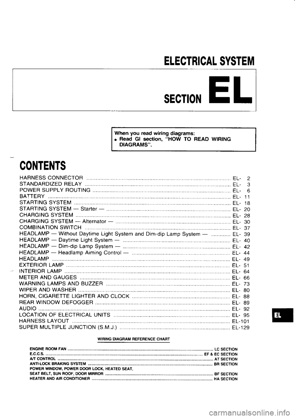
When you
read wiring
diagrams:
o Read
Gl section, "HOW
TO READ WIRING
DIAGRAMS''.
CONTENTS
STARTING SYSTEM
STARTING SYSTEM -
Starter -
...
CHARGING SYSTEM
CHARGING SYSTEM*
Alternator -
COMBINATION SWITCH ....
HEADLAMP -
Without Daytime Light System and Dim-dip
Lamp System
HEADLAMP -
Daytime Light
System -
HEADLAMP -
Dim-dip Lamp
System -
HEADLAMP -
Headlamp Aiming
Control
HEADLAMP
EXTERIOR LAMP ............
tNTER|OR 1AMP ............
METER AND
GAUGES
WARNING LAMPS AND BUZZER
WIPER AND WASHER
HORN, CIGARETTE LIGHTER AND
CLOCK
REAR WINDOW DEFOGGER EL-
2
EL- 3
EL- 6
EL- 11
EL. 18
EL.20
EL- 28
EL- 30
EL- J/
EL. 39
EL- 40
EL- 42
EL. 44
EL- 49
EL- CI
EL- 64
EL. OO
EL- 73
EL- 80
EL- 88
EL- 89
I::L- J Z
EL- 95
EL-101
EL- 129
LOCATION
OF ELECTRICAL UNITS
HARNESS LAYOUT ...,........
SUPER MULTIPLE JUNCTION (S.M.J.)
..........
URING DIAGRAM REFERENCE CHART
ENGINE ROOM FAN
LC S€CTION
E.C.C.S. EF & EC SECTION
ANTFLOCK BRAKING SYSTEM
A/T
CONTROL AT SECTION
BR SECTION
BF SECNON
HA SECNON
POWER
WINDOU POWER OOOB LOCK,
S€AT BELT.
SUN ROOF.
OOOR MIRROB
HEATER ANO AIB
CONDITIONER HEATED
SEAT.
Page 1118 of 1254
POWER
SUPPLY ROUTING
FTl eQ Eo
BOD GR!UND
ACCESSORY 2
R @R/L
@ FusE
8-0cK
ref o
|ue @
rl.
i2 20A
ts,
t0i tE) Wiring
Diagram (Cont'd)
'etffi !T]CR 11I
RROF fil TI -:
AF'R IEATER,
REAR '\l PER
A:.1,1 fr!5ts:F
- -.--
o\-I-t. o-
lB *
EE f. L-r frlEg ..
- --l
BR +
E\Grf= CCTTFC;5.5TEfr
w/6@
r -
;3ffi
",^-m . *
IC;A";l':l',.?EiiJ...oo ^.."
I AIL,
C.EARAN'E IND
L I CE\CE LAIIP5
SIART
ENGI NESI
GNAL,
CONTROL SYSTEI]
G ZARO WAFNI
NC
R/\1 +ffi
o
fn l!
cr '
Lr']P
"'.-'-.L--_ REAR !
I NDOW
DEFOG'Et
@ L,p
REAR ELOW:P I]ITOII
:GNII]'N
RELAY'L
(i;\
8/n-1 1)
TAIL, CL:ARANCE, .I CENCE
I LLL|l I
NAT I ON LAiPs,
WARNI NG BUZZER,
tsEADLAI'O AIIJING LONTROL
ENCI NE
iJOT FAN
5I3-EI], CLOCK,
A.]DI O, ':. LE!EL I]NI -,
l --LrNi NAT
I ON CONTRaIL SYS:Eir
: \TER:
OR ANO 5POT LAIIP
r3
EL.7EACK
CCOR
LICK
MELTOSA
Page 1120 of 1254
POWER
SUPPLY ROUTING
ACCESSORY RELAY I
GNI TI
ON
-2 -1
RELAY-I
T-t r:t T-t
lan I ll /rn l/rnll
a€ ftlt lt-rjl I
airD r
'J FUSE BLOCK
"l P.
dP,
t" P. dP,
*L 20A
O
L0A 6
IOA €D
LsA @
r0AO&€)
LsA @
L0A @
lsA @ Wiring
Diagram (Cont'd)
oR+@
o"re*@
DOOR IlIRROR
WITH IIIRROR HEATER,
REAR WIPER AND WASIIER
RADI ATOR FAN RELAY,
REAR HEAIER
SYSIEN, REAR
A,zC
ilo6fE S9i'ff;o'.'"'n
TAIL, CLEARANCE, LICENCE AND
I LLUIlI NAT
I ON LAI1PS,
iYARNI NG BUZZER
SIARI SI GNAL,
ENGI NE
CONTROL SYSTEIl
G+M
G/B+m
",**ffi BR+m
IlETER ANO
GAUGES, WARNIIG
LAI1PS,
SIJISTF iISEI 3}3IEX
HF
ENGINE ROOtl
FAN
SYSTEIl, CLOCK,
AUDI O, CI L LEVEL UNI T,
I LLUIlI NATI ON
CONTROL SYSIEII
L
EL.9
Page 1121 of 1254
POWER
SUPPLY ROUTING
Fuse
a. It fuse is blown,
be sure to eliminate cause of problem
before installing
new fuse.
b. Use fuse
of specified rating.
Never use fuse of more than
specified rating.
c. Do not install fuse in
oblique direction; always insert it into
luse holder properly.
d. Remove fuse lor clock if vehicle is not
used for
a lono
period of time.
Fusible Link
A melted
fusible link can be detected
by visual
inspection.
lf its
condition is questionable,
use circuit tester or
test lamp.
CAUTION:
a. ll lusible link should melt, it
is possible
that critical
circuit
(power supply or large
current carrying
circuit) is
shorted.
In such a case, carefully
check and eliminate cause of
problem.
b. Never wrap periphery
of fusible link with vinyl
tape.
Extreme care
should be taken with this link
to ensure that
it does not
come into contact with any
other wiring
harness
or vinyl
or rubber pans.
EL-l0