Page 877 of 1254

CHECK
AND AD.IUSTMEI.IT
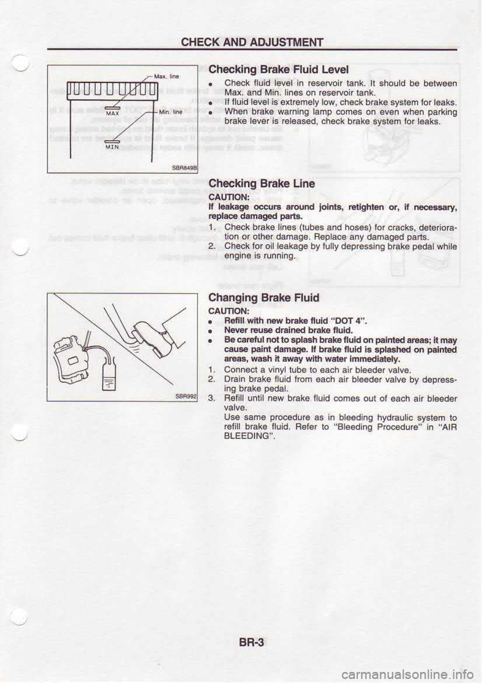
Checking B6ke Fluid
lrvel
. Ch€ck
iluid l€v€l in
€seruoir tank. tt sholtd be belw€6n
Md. and Min.lines on resetoon lank.
. ll
tluld level is enremely low, ch€.k b€kB syslem lor leaks.
. Wh6n brak€ waFi.q l.mp.on€6
o. eve. when paltr.O
bmk6 l6v6r is €leased.
check b6ke svsieh tor l€aks.
Checking Brake Lin6
t l@lGdo edE.Nnt jolnl6,
G{ghlen or, n E.gry,
1. Check bak6lin6s (lubes
6nd hos6) lorc6cks,
deleiura-
tion or olh damaa6. B€p
aca any damaged pa.ls.
2. Chock tor oil l€akaga
by l!
ly
depessing b €ke p€da
whit€
Changlng Srake Fluid
. Renll -nh |w bE G 6uld
"DOT 4".
. N@r
Eus dEln€d bE*€ nuld.
. B€€ratulmtlo.pL.h
b6t fuid on pdnt€d.|6i
i m.y
€@ p.lnt.t
mrgE. r bEk nuid
b 6pla3hcd on pdnbd
a|@i Msh n e.y wir'| w.ter
Inmedlatety,
1. Co.ned a vinvl lub€ lo €ach air bleedd valve.
2. DG n b6ke I u d lbm €ach
air b eeder valve bv deorss,
3. F€lill unlil
new b6ke fluid com6s oul ol6ach
an bleeder
Us€ sm€ prcc€dlF
a. in bleed ng hydraulic sysr€m ro
€lli brak€ lluid.
F€fer io Beedng PrccedlE" i. 'AlR
BLEEDING',
Page 951 of 1254
ON.VEHICLE
SEBVICE
f4 s- Checkidg
and
Adjusting Ddve B€lts
Beler lo secl
on MA ior
Drve Belt Inspecton
Checking Fluid
Level
Fluid Levershoud be
cheoked usinq HoT
Enge on
dipslrck
at iluid lenoeratur€s ol
50 b ao'C (122
lo 176'F) ot
usmg
'coLo" Gnoe on
d pstck
allluidlempeEtures ol0
to 30'c (32
. Rdnrended fuid
b adomsiic Transmlslon Fluid
Checking Fluid
Leakage
Check lhe
linos lof mproper allachmenl
and lor
l6aks, c6cks,
damage,loose conneclions chal
ng or deleio€lion.
i Bun engine b€ftveen
idLe speed and
1,000 .pm
M.k€ suE lentEr.tuE ot
fluld ln oil
l.nk des to 60lo 30Pc
2. Turn
s1€efne wheel rqhl-to'etl
seve6 limes.
3. Hold sl€ernq
wheelal each 'ock'poslio.lorr
ve s.conds
and carelully check
lor fu d eak.ge
Do not hold the 3teeting sh.€l
in a lek d pGiton
lor moE
4. ll tluid l€akace al
conneclo6 s
noliced, loosen rar€
nll
tro not ovedlgtn n
connectd as lhiB
c.. damage Orlng.
t
i
i
!
t
i
Y3 ri
l:
E
Page 952 of 1254

ON.VEHICLE
SERVICE
Bl€€dlng Hyd6ulic
Syslem
L Baise iiont 6nd of vehi.le
lnllwheels a€ cl6ar ol
the
2. Add lluid
inio oilla.klo specili€d
evel Meanwhite quickty
lurn deenng wh6el lully
to right
and ett and tiqhity
tolch
B€peal sleeling wheel opBr.rion u|li lllid
tevet no ong6r
Rep€l sl€p 2 abov6.
. -6rp6l€
ar bleed'rg fll eus€ r€ ,ol,osng
lo olcu.
when lhis happens, bl6€d.n
again
a. Genehton ol an bubb 6s in €seflo r i'nk
b. Gen€Ellof
ol clicki.g noi* in oi pump
c. Exesilre
buzz ng in oilplmp
Whi6 5e ver-Lte 's
sarion€-y o whte
novnq -€
stee'i.g
wheal slowly, lluid nois€ may
occur in the valvB or oil pump.
Tl^': nobe s 'nh€E.l r
rr^'s sleefg syst€n.
and 'l
{t nor
arlecl p€rtomance
o' durab ry ol lh€ sysrem
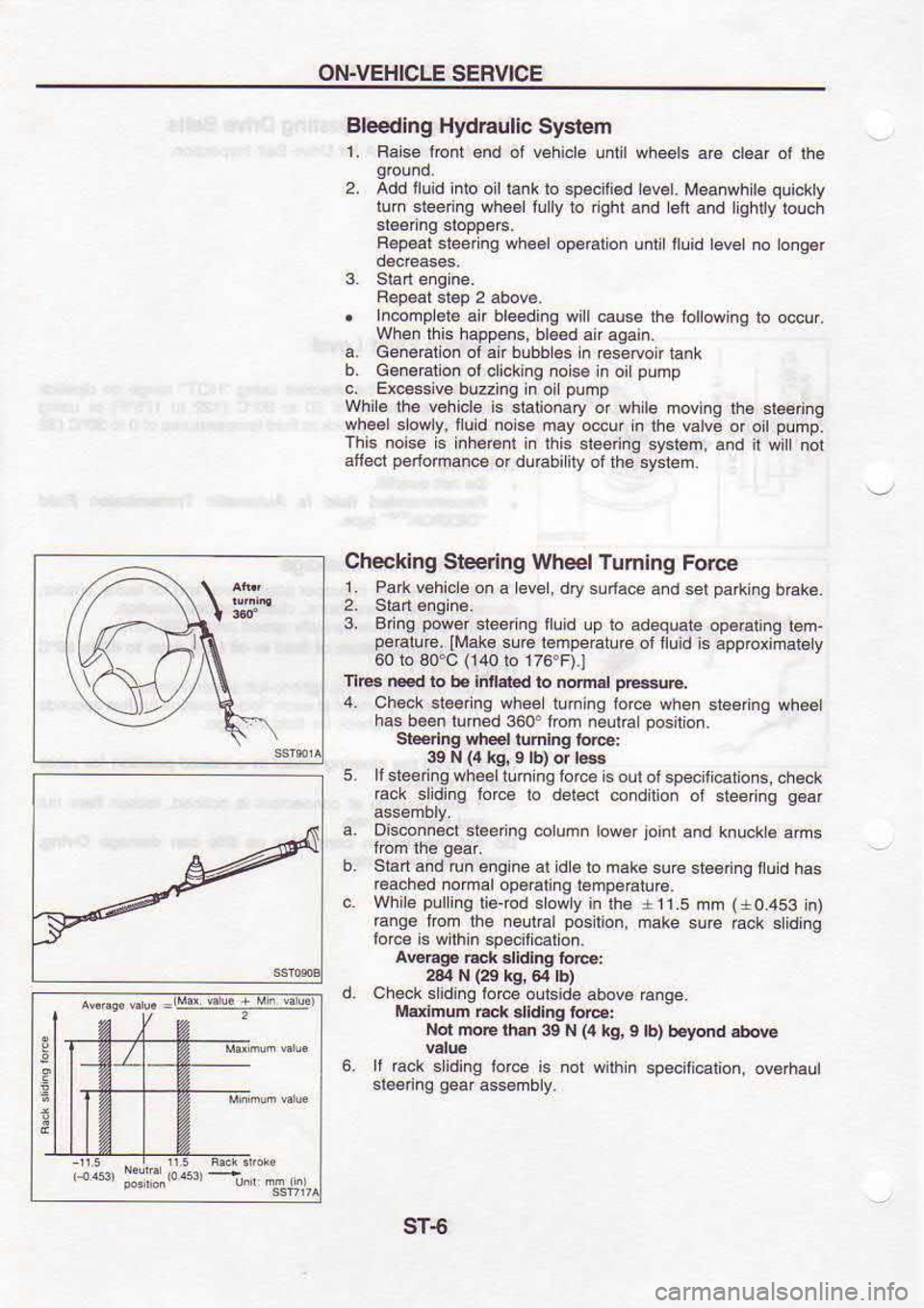
Checking Steering Wheel Tuming
Force
' oaAv€h'.6
dn a level,
dry sLd.ce
a.d sel
ea*'no br:re
2. Slan€ndrn6
3. Bdng poiwer
steeing lllid
!p to adequab op€ratinq
iem-
peraturc. ll'rake 6u@
lempeEture otlluid s
apprcximabty
60 lo 30'C (140lo
176.F).1
Tl@ Ed ro h.Iniated
to nornd pl*(E,
4. Ch€c qt@'ng
whee r.minq'Io'ce s
ea s.eernq wheel
has b€en
turned 3606 kom neul'a posrt'on.
S_teedng ehe6l turning io@:
39 N (4
ks, 9 lb)
or la
5. llsr66rifg wheeltln
ngtorc6 i6
outofspeciti€lons, check
raok slding lorc€
lo delecl condlion ol
steeing g€ar
a. Oisconn€cl
slaerno @lumn low6r
ioi.t and
knucke ams
Stan snd 'un
e.g'ne al d€ iom.kesure
st€€ nq tlu'd
has
rcached noroar op6rarinq remperature.
while puling
li6{od slowly
in lh6 r11.5
mm (+0.453
n)
ra.q€ rrom rhe
nellral posilion,
make s!rc Ecl 6tid'.o
lorce is w'lh
n sp€cihcai'on
a@Eg€ Eck didlng
force:
234 N (29
kq, 64 tb)
Check sliding iorce
oulside above
Mdimum Eck slldlng for:
Not moe rhin 39 N
{4 kg,
9
ll rack sliding lor.e
is nol wilhtn
!
sT6
Page 1160 of 1254

HEADLAMP
PUSH Io
\
_@. PUSH
lo Bulb
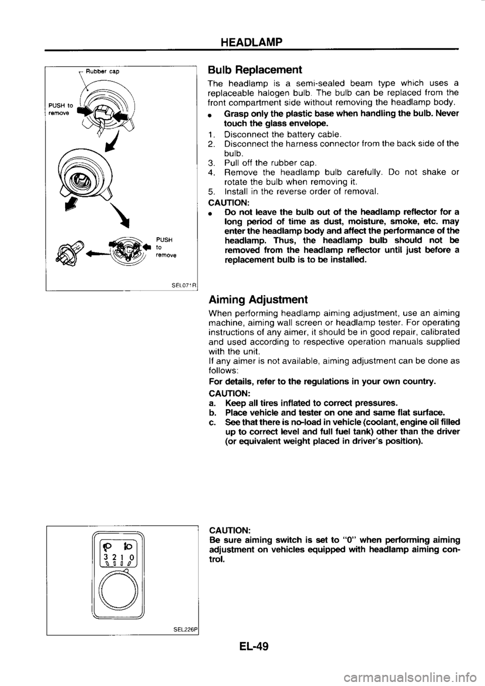
Replacement
The headlamp is
a semi-sealed beam type which
uses a
replaceable halogen
bulb. The
bulb can
be replaced from
the
f ront compartment side without
removing the headlamp
body.
r Grasp
only the plastic
base when
handling the bulb.
Never
touch the glass
envelope.
1. Disconnect the
battery cable.
2. Disconnect the
harness connector from
the back side ol the
bulb.
3. Pull
off the
rubber cap.
4. Remove the headlamp
bulb carefully. Do
not shake or
rotate the bulb when removing it.
5. Install
in the reverse
order of removal.
CAUTION:
o Do
not leave the bulb out of the headlamp
reflector for a
long period
of time as dust, moisture,
smoke, etc. may
enter the headlamp
body and aflect the pedormance
of the
headlamp. Thus, the headlamp
bulb should not
be
removed from
the headlamp reflector until just
before a
replac€ment bulb is
to be installed.
Aiming Adjustment
When performing
headlamp aiming adjustment, use
an aiming
machine, aiming wall screen or headlamp
lester. For
operating
instructions of any aimer, it should be in good
repair, calibrated
and used according to
respective operation manuals
supplied
with the unit.
lf any aimer is
not available, aiming adjustment can be done as
Iollows:
For details, reter
to the regulations in your
own country.
CAUTION:
a. Keep all tires inflated to correcl pressures.
b. Place vehicle
and tester on one
and same flat surface-
c. See that there
is noload in vehicle (coolant,
engine oil filled
up to correct level
and tull tuel tank) other than the driver
(or equivalent weight placed
in driver's position).
CAUTION: Be sure aiming switch
is set to "0"
when performing
aiming
adiustment on
vehicles equipped with
headlamp
aiming con-
trol.
lF-bl
l3 2
I 0l
L,\_-! S l l
,n
[) \/
EL-49
Page 1184 of 1254
WARNING
LAMPS AND BUZZER
Warning Lamps/Schematic
_s*_ ---
* ABsco
ioLL,.rrr
"5:_ f.
IrF -_l
# ts
Eac s:oNiRC- rNli
R! O
L'] @
BRAKE SEAT
8EL- L]N:
T
PARKI NG BRAKE SW: T'ts
ERArE FL!lt,
LE VEL SY! I TCts
OIL PRESSURE
SW: iTts
I,O:L LE !E.
!,NI'
C,l L LE /EL
ENGI NE O; L
LE! EL UNI T
:
c
c)a o
c.-^ o
a666 - -
g\11
=; :a I
=^l
: .l
rn
r:i
.n vi9
a-l]o .III
t; ',,
c G) 60"
9""
:3
c!EL.E,EL
I O ,l
.-- c+l
il L o!!
t -- ALTERNATOR
, FUEL LEVEL SWI -CH
FJE! FI
LIER sWI TCFI
crcvl or.rtr- t L urtt
viE
Ll CONIROL LrNl
I (EQ
T-t
-@F'.rcfr.rl
RH
LH
EL-73
Page 1190 of 1254
WARNING
LAMPS AND
BUZZER
----](-
Continuity
Bsnery Diode
Check
o Check
continuity using an ohmmeter.
o Diode
is functioning properly
il test results are as shown in
the f
ioure
at left.
o Diodes
for warning lamps are built into the combination
meter orinted circuit.
Refer to "Combination
Meter".
Engine Oil Level Unit
Check
1 . Connect as shown in the figure at left.
2. lf test lamp comes on when disconnecting terminal
O from
battery ground,
engine oil level
unit is
normal.
Warning Buzer
Check
F \zz
fi*ffi=l
| | r:
rL----rr l
#/\
EL-79
Page 1208 of 1254
LOCATION
OF ELECTRICAL
UNIT
L.H.D. MOOEL
Accessory relay-3
{Blue)- Passenger
Compartment -
Front
Rear tog lamp
relay (Blu6)
Combination flasher
unit
' R€ar wip€r amplit€r
Rear healer r€ray (Blue)
Glow control unlt (LO20-ll)
Daytime |ght conirol unit
S€at bett tim€r
",":""-.:;'l
"-,*-".: (sR20oE.
GA16DE)
Engrne control
unn
(LD20-l)
Slop lamp swilch
Accessory r6lay-2 (Blue)
Accessory r€lay-1 (Blue) I
I
LABS control unil
(sR20DE)
Power wndow relay (Blue) I
I L
e"ot" room ran
conrrol
I 'EnSrne
oil level
unil
'E C.C.S. conlrol unii
lgnrlron relay
lElue)
EL-97