Page 891 of 1254

BRAKE
SOOSTEB
Inspection
OUTPUT FOD LENGTH CHECK
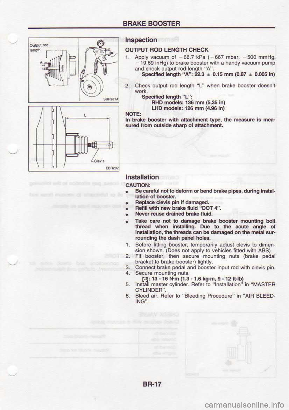
1. Appy vacuum ol -66.7
kPa (-567
19.69 inHg)to brak€ booslor with a
and oheok output od efgth A'.
Sp*ified l€nglh "A':223 r 0,15
2. ch..k
oulput rcd enqrh '1"
when b6ke booster d@snt
Spelfi.d lsqlh L :
FHD modeh. 136 mm 1s.35 in)
LHD nod€ls: 126 nn {4,96lnl
NOTE:
In brake bo6r.r wth att chmnl rype, lhe me@e
l. m@
{r€d lrom outllde sharp ot atrachrent
lnslallalion
. 84 6Etul not to d,eiom or bend bhke plp6,
durlnq lrclal-
. Fi.ds
cl6vl.
dn il
dsnEgEd,
. Rcnll
wnn tw
bnt. nukl
"DOl4'.
. llow
€u$ d6ln€d bEk f!ld,
. T.16
eE nol ro ddEg5 b:k€ [email protected] munlinq
bol
ihEd ytEn
iBr.lling. rr€
b !E 4ute angle ol
lMi.ll.don, tt€ inrEd3 6n b. damagEd on rh. reral sur
rcundl.g thc d6h p.EI
hor6,
L Betoroliitirg boosler, l€mpoEdy adjusl cl€vis lo dimen'
sion sFown (Do€s
nor.pply ro v6hicle6lit€d ulh ABS)
2. Fil
boost€r. lhen 6€cu€ molnling nuls (bEke
peda
3,
5. btackal
to brake boosier) lighily.
Connecl brake pedal
and booster input rod with clevis pin.
lol: t3 -
16 N.n {i,3 -
1.6 km. 9 .
12 lt lb)
rnsislr m'ds.vr;d Rdd i.
"rnd'rdioni n
"MAsrFF
6. Bleed air. Feiq lo 'Aleedinq
Procedue" in AIR BLEED-
ING'.
BR-l7
Page 958 of 1254
STEERING
WHEEL
AND STEEBING @LUMN
Inspeclion
. when
sr66 nq whe6l@n nol be olaled sfrooihly, check
the sieedng @lumn lor
tha iollowinA
matl€6 and cplace
a. ch€ck
co umn b€afngs lor damage or unevenness. Lubri
€ie wilh e@mmend€d muii'porpos gBas.
or rsplaco
slee .g column as an assembly, it
ne@ssary,
b. ch€ck jackel
tube for detomation or breakage. Fep ace il
. When
lhe vBhc. is involved in a lighl co lision,.neck @l-
!m. length '1".
l, it is nor wirhin sp€cilierions, €pacB
$eennq @lunn as a. assembly.
"lr" 276
mm (10.6
in)
't+" 415.7 mm (16.36
In)
sT-l2
Page 963 of 1254
STEERING
GEAR
AND LINKAGE nual
steerln
In6pectlon (Cont'd)
Check ball joinl
lor axiaL end play.
lle{d oui.r
b€ll
iolni:
ls rhln 05
mn (0J20
In)
Tlerod InFr bsll jo|m:
Check condllion ol dusl cover ll
il i. cEck6d exdssively,
Assembly
NE-ROD AND BOOT
1 lnslall boor on lle @d inner socket.
2. Apply locking
s€alant 10 lhreadod ponion
ol inner s@kel
and install llejod inner .ockel io hck
end log€lhor with
spacd and n€w
lek plal..
3. Inslall lock nul and oLI6r so.k€l
lo inn€r $ckot. Adjust li6-
rod length
"l'and tqht.n
lock
nul.
r6f!d rmgth
"L'': lt
te.io s.D.s.
Sm*d lmgth '.2":
txl,6 nn (1.716In)
4. Measu€ rack slroke.
M€..ud l.n!m r':
R€Lr to s,Ds.
5. Installbool io q6ar
housing.
Eeide h6t lllng
b@l *r th€ 6i1 ., srf*4 b.lwn boot
sT-l7
Page 1136 of 1254
STARTING
SYSTEM _
Starter _
Srush spring Brush
Check
BRUSH
Check wear of brush.
Wear limit
length:
Refer to S.D.S.
o Excessive
wear...
Replace.
BRUSH SPRING PRESSURE
Check brush
spring pressure
with brush spring
detached from
brush.
Spring pressure
(with
new brush):
Refer to S.D.S.
o Not
within
the specified
values... Replace.
BRUSH HOLDER
1 . Perform
insulation test
between brush holder (positive
side)
and its base (negative
side).
Continuity exists. ... Replace.
Check brush to see if il moves
smoothlv.
lf brush holder is
bent. replace
it: if
sliding surface is dirty.
ctean.
ilv between brush holder
and....
Negative brush
rsolat
Positive brush
Armature Check
1 .
Continuity test (between
two segments side by side).
o No
continuiw...
Reolace.
2.
EL-25
Page 1147 of 1254
CHARGING
SYSTEM -
Alternator -
Service Data
and Specifications (S.D.S.)
ALTERNATOR
Type LR190-719
1R180-735I 120.335.000
HITACHI BOSCH
Engine SR2ODEGAl6DE LD20rl
Nomina rating
V-A12-90 12 -
80 12-90
Ground polarity
Negalrve
l\,4inimum revolution
under no-load
(When 13 5 volts
is
applred) rpm 10500
Hot output current A./rpm234300
63/2500
87/5000 2311300
63/2500
77l5000 16.5/1300
68.5/2500 B3/5000
Regulated oulpul vollage
V 14.114.7
Minimum length ot brush mm (in)
6 0 (0
236) t
010.276) 10
0
{0.39)
Brush spring pressure
N (9,
oz) 1.000
3.432
(102 350,
3.60 -
12.34) 1.863
3.040
(1S0 -
310,
6 70 -
10.93) 1.9
(194,
6 84)
Slip nng
minimum
outer
orameler mm (1n) 26.0
(1 024) 30
6 (1.20s)
1s.3 (0
602)
E1.36