Page 1118 of 1254
POWER
SUPPLY ROUTING
FTl eQ Eo
BOD GR!UND
ACCESSORY 2
R @R/L
@ FusE
8-0cK
ref o
|ue @
rl.
i2 20A
ts,
t0i tE) Wiring
Diagram (Cont'd)
'etffi !T]CR 11I
RROF fil TI -:
AF'R IEATER,
REAR '\l PER
A:.1,1 fr!5ts:F
- -.--
o\-I-t. o-
lB *
EE f. L-r frlEg ..
- --l
BR +
E\Grf= CCTTFC;5.5TEfr
w/6@
r -
;3ffi
",^-m . *
IC;A";l':l',.?EiiJ...oo ^.."
I AIL,
C.EARAN'E IND
L I CE\CE LAIIP5
SIART
ENGI NESI
GNAL,
CONTROL SYSTEI]
G ZARO WAFNI
NC
R/\1 +ffi
o
fn l!
cr '
Lr']P
"'.-'-.L--_ REAR !
I NDOW
DEFOG'Et
@ L,p
REAR ELOW:P I]ITOII
:GNII]'N
RELAY'L
(i;\
8/n-1 1)
TAIL, CL:ARANCE, .I CENCE
I LLL|l I
NAT I ON LAiPs,
WARNI NG BUZZER,
tsEADLAI'O AIIJING LONTROL
ENCI NE
iJOT FAN
5I3-EI], CLOCK,
A.]DI O, ':. LE!EL I]NI -,
l --LrNi NAT
I ON CONTRaIL SYS:Eir
: \TER:
OR ANO 5POT LAIIP
r3
EL.7EACK
CCOR
LICK
MELTOSA
Page 1120 of 1254
POWER
SUPPLY ROUTING
ACCESSORY RELAY I
GNI TI
ON
-2 -1
RELAY-I
T-t r:t T-t
lan I ll /rn l/rnll
a€ ftlt lt-rjl I
airD r
'J FUSE BLOCK
"l P.
dP,
t" P. dP,
*L 20A
O
L0A 6
IOA €D
LsA @
r0AO&€)
LsA @
L0A @
lsA @ Wiring
Diagram (Cont'd)
oR+@
o"re*@
DOOR IlIRROR
WITH IIIRROR HEATER,
REAR WIPER AND WASIIER
RADI ATOR FAN RELAY,
REAR HEAIER
SYSIEN, REAR
A,zC
ilo6fE S9i'ff;o'.'"'n
TAIL, CLEARANCE, LICENCE AND
I LLUIlI NAT
I ON LAI1PS,
iYARNI NG BUZZER
SIARI SI GNAL,
ENGI NE
CONTROL SYSTEIl
G+M
G/B+m
",**ffi BR+m
IlETER ANO
GAUGES, WARNIIG
LAI1PS,
SIJISTF iISEI 3}3IEX
HF
ENGINE ROOtl
FAN
SYSTEIl, CLOCK,
AUDI O, CI L LEVEL UNI T,
I LLUIlI NATI ON
CONTROL SYSIEII
L
EL.9
Page 1121 of 1254
POWER
SUPPLY ROUTING
Fuse
a. It fuse is blown,
be sure to eliminate cause of problem
before installing
new fuse.
b. Use fuse
of specified rating.
Never use fuse of more than
specified rating.
c. Do not install fuse in
oblique direction; always insert it into
luse holder properly.
d. Remove fuse lor clock if vehicle is not
used for
a lono
period of time.
Fusible Link
A melted
fusible link can be detected
by visual
inspection.
lf its
condition is questionable,
use circuit tester or
test lamp.
CAUTION:
a. ll lusible link should melt, it
is possible
that critical
circuit
(power supply or large
current carrying
circuit) is
shorted.
In such a case, carefully
check and eliminate cause of
problem.
b. Never wrap periphery
of fusible link with vinyl
tape.
Extreme care
should be taken with this link
to ensure that
it does not
come into contact with any
other wiring
harness
or vinyl
or rubber pans.
EL-l0
Page 1135 of 1254
STARTING
SYSTEM _
Starter _
Magnetic Switch
Check
Before starting to check, disconnecl battery ground
cable.
Disconnect "M"
terminal of starter motor.
Continuitv test.
Pinion/Clutch Check
1. Inspect pinion
teeth.
o Replace pinion
if teeth are worn or damaged. (Also
check
condition of ring gear
teeth.)
2. Check to see if pinion
locks in one
direction and rotates
smoothly in
the opposite
direction.
o lf
it
locks or rotales in
both directions,
or unusual
resistance
is evident. ... Reolace.
REDUCTION GEAR TYPE
3. Inspect
reduction gear
teeth.
o Replace
reduction gear
it teeth are worn or damaged. (Also
check condition
of armalure shaft gear
teeth.)
Continuily
between Continurty
Action
"S" lerminal and switch
DOOy Yes
o.K.
No Replace
"S" terminal and "l\,t"
terminal Yes
o.K.
No Replace
EL.24
Page 1138 of 1254

STARTING
SYSTEM -
Starter -
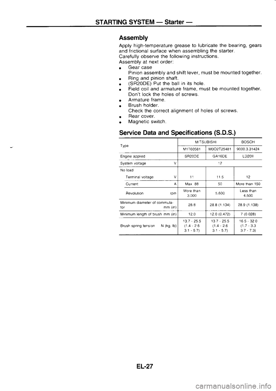
Assembly
Apply h igh-temperature grease
to lubricate
the bearing, gears
and frictional
surface when
assembling the starter.
Care{ully observe
the following inslructions.
Assembly at next
order:
. Gear
case
Pinion assembly and shift lever,
musl be mounted together.
. Ring
and pinion
shaft.
. (sR20DE)
Put the ball in
its hole.
o Field
coil and armature frame, must
be mounted
together.
Don't lock the holes of screws.
o Armature
f rame.
o Brush
holder.
Check the correct alignment of holes
of screws.
o Rear
cover.
. Magnetic
switch.
Service Data
and Specifications (S.D.S.)
Type M
TSUBISHI BOSCH
t\.rf 1 T6
05 8 I
M002T25481 9000.3
31424
Engine applied SR20DEGA16DE LD20rl
System voltage V 12
No load
Terrnrna voltage Vt1 115
Current A
[ra.x
88 50[,,lore
lhan 150
Bevolubon rpmtulore
than
3 000 5.600Less
than
4,500
Minimum diameter of comrnula-
lor mm (rn) 288
28 8 (1
134) 28.9 (1.138)
Mrnimum lenglh of brush mm (in)
12.0 12 0 (4.472)
7 (0
028)
Brush spring tens on N (kg,
lb) 13.7
25.5
(1.4 26
3.1 -57) 137
(1 .4
3.1 -
2.6 16.5
32.0
(1.7 -
3.3
3.7 -
7 .3)
EL.27
Page 1144 of 1254

CHARGING
SYSTEM -
Alternator -
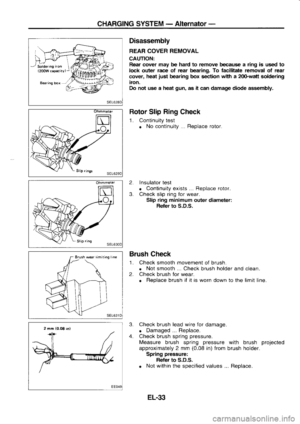
Soldering aron
{200W capacirv, Disassembly
BEAR COVER REMOVAL
CAUTION: Rear cover may be hard to remove because a ring is used to
lock outer race
of rear bearing. To facilitate removal of rear
cover, heat
iust bearing
box section with
a 2oGwatt
soldering
iron.
Do not use a heat gun,
as it can damage diode assembly.
Rotor Slip Ring
Check
1. Continuity test
o No
continuity... Replace rotor.
2. Insulator
test
. Continuity
exists ... Replace rotor.
3. Check slip ring for wear.
Slip ring minimum
outer diameter:
Refer to S.D.S.
Brush Check
'L Check smooth movement
of brush.
. Not
smooth ...
Check brush holder
and clean.
2. Check
brush for
wear.
o Replace
brush if
it
is worn down to the limit line.
3. Check
brush lead
wire for
damage.
o Damaged...
Replace.
4. Check brush spring pressure.
Measure brush spring pressure
with brush projected
approximately 2 mm (0.08
in) from
brush holder.
Spring pressure:
Refer to S.D.S.
o Not
within
the specified values ... Replace.
Ohmmeter
Erush woar limiting
line
2 mm (0.O8
in)
EL.33
Page 1159 of 1254
HEADLAMP
-
Headlamp Aiming
Control-
A Cil
Lighting swrlch lsl
5r
ts EI'H)
mtri
mti Troublediagnoses
SYMPTOM: Headlamp
aiming does not operate.
E
Check 10A fse
al luse
block.
(Refer to "POWER
SUPPLY
ROUTING.")
POWER
SUPPLY CIRCUIT
CHECK (For
aiming switch)
Check if
12 volts
exist between
terminals O and
aO.
AIMING SWITCH CHECK
Check continuity between termi-
nals at each switch position.
GROUND CIRCUIT
CHECK
FOR AIMING MOTOR
Check continuity between termi-
nals rj)
and body grround.
Continuity exists ... O.K. Bepair
harness between
aiming
motor and body ground.
POWER SUPPLY CIRCUIT
CHECK
(For aiming motor unit)
Check il 12 volts
exist between
terminats 'O,
@, @, @ and
o Volt-
meter
termina Voltage
[V]Aiming
switch
posrtron
o Approx.
12"0"
o "0"
.;\ Approx.
12"1"
0 "1"
o Approx.
12
0
o Approx.
12,.3,,
0 "3"Check
harness
between aimjng
switch and aiming motor
unit.
EL.48
Page 1174 of 1254

EXTERIOR
LAMP
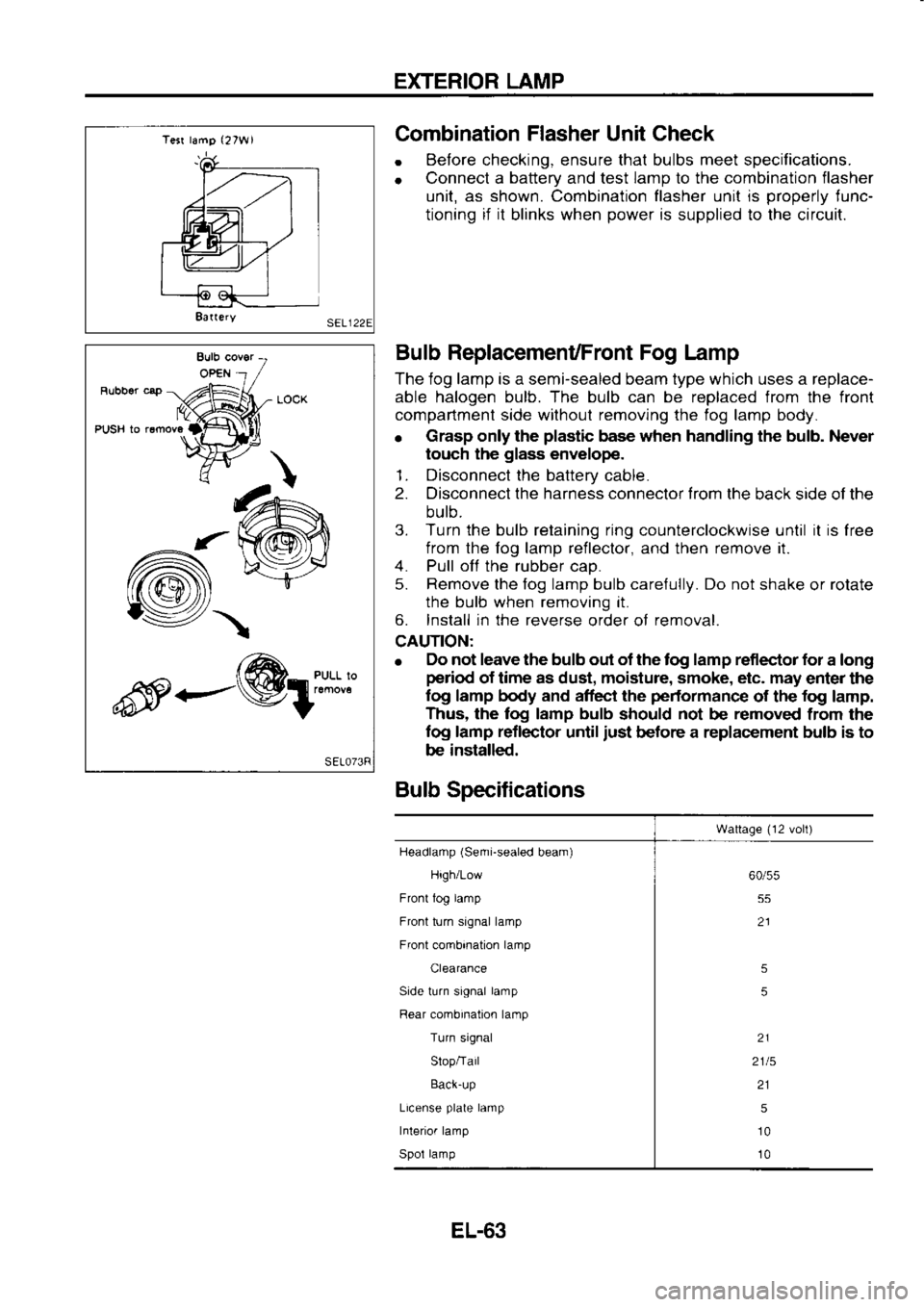
Tesr lamg (27W1
8a(ery Combination
Flasher
Unit Check
. Before
checking, ensure that bulbs meet specifications.
o Connect
a battery
and test lamp
to the combination
flasher
unit, as shown. Combination flasher unit is properly
lunc-
tioning if it
blinks when power
is supplied to the circuit.
Bulb ReplacemenUFront Fog Lamp
The iog lamp is a semi-sealed beam type which uses a replace-
able halogen bulb. The bulb can be replaced from the front
compartment side withoul removing the fog lamp body.
o Grasp
only the plastic
base when handling the bulb. Never
touch the glass
envelope.
1. Disconnect the battery
cable.
2. Disconnect the harness connector trom
the back side of the
bulb.
3. Turn the bulb retaining ring
counterclockwise until it
is
free
from the fog lamp reileclor,
and then remove
it.
4. Pull off
the rubber
cao.
5. Remove
the fog lamp bulb care{ully. Do not
shake or rolate
the bulb when removing it.
6. Install in the reverse
order of removal.
CAUTION:
e Elo
not leave the bulb out of the tog lamp reflector for
a long
period of time as dust, moisture, smoke, etc. may
enter the
log lamp body and affect the performance
of the fog
lamp.
Thus, the log lamp bulb
should not
be removed
from the
fog lamp reflector
until just
before a replacement bulb is to
be installed.
Bulb Specifications
Wattage (12
volt)
Headlamp (Semi-sealed
beam)
High/Low
Front tog lamp
Front turn signal lamp
Front combination lamp
Clearance
Side turn signal lamp
Rear combination lamp
Turn signal
Slop/Tail
Back-up
License plate
lamp
Interior lamp
Spol lamp 60/55
55
21
5
5
21
2115 215
10
10
-/\
<---@1:"*:l'l
EL-63