Page 701 of 1254
E.G.R.
SYSTEM E
@@
oo
E6 N
6E N
tr6 Inspection
(conr'd)
EG.F. CONTBOL SOLENOIO VALVES
Check lh6 solenoid
valves lor nomal oporalion,
allef disoo._
necling lhe onnetor
and a I th
Supply $e solenod vrlv.s
wilh bcttery wllaqe, end ch6.k
whonrer lhe@ 6 @nlmurtv belu€on Dois A,
B and C.
POTENNOMEIEF 1 . D sconn€cr
oolelnlometer @nne.tor
and
@nn€ct ohmm6'
2. Mak6 .ur€ thal lhe rcsidanoe changes wh€n
th6 conrrol
l€v€r opening angl€ ol the luelinjeclion pump
s chang€d.
ENGINE REVOLUNON SENSOR
1. Whi e idling .ng ne, check AC voftaqe acrcss lem nal6
@
and 6).
EnglF ldllng:
appbx. o8v
Ch€c1 ll-ar AC vo
rag6 'nc€a.e6
wl'e. €rqin6 speed is
2. ll vohagB s nor withi. speciti€tlons, @ndlct a @nlinuily
Appd. 5
ko
{@ndnuiry eblilh€O
4 puls3tl
.nlitu doluton
IITATEF TEMPEFATUFE SENSOF
. Check
rsislan@ ol wal€r lempedurc sener.
R.fer ro oulcKclow sYsTElr.
EF & EC.4{X)
Page 727 of 1254
HYDRAUUC
CLUTCH
@NTBOL
Cluicfi Damper (SF|2oDE
engine mod6l5
only)
9$oi.x.u,\.,/ bf E@6ms'
4turbpid{sFbt
INSPECTION
. ch6ck
cylnder and pislon
rubblng sufa@ lor unev€n w€ar,
rud or dama06. Beplace if necGsary.
. Check
dampd rubber
and prslon
cup lor cr&k., d€roma-
tion or damage. F6plac6
il n€€ssary.
cL{
Page 885 of 1254

LOAD
SENSING VALVE
Inspeclion and Adius:menl(Cont'd)
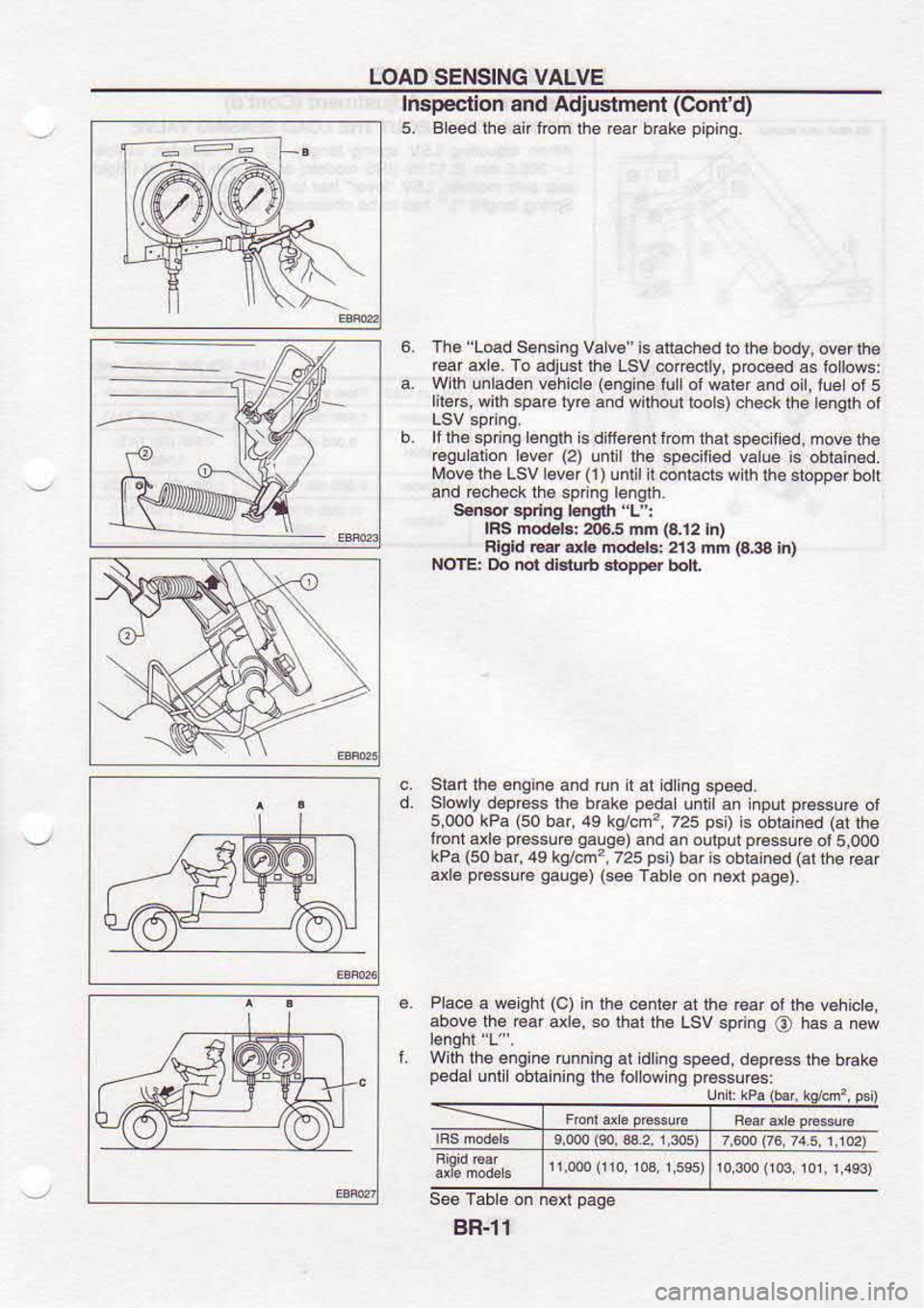
5, Bleedlhe anlom lhe r6af brake pipinq.
The 'Load
Se.s ng Valv€ is attachad
to the body, ovor lh€
reai axle. To adjust lh€ Lsv
@irectly, p@ce€d
as iollows:
With unladen v€hicl€ (engine
lullol wal€r and oil,lle
of5
lilerc, wilh sparc lyr6
and wilhoul lools) ch€ck lhe lenath
ot
lf rh6 spnna bnalh
is d llercnt trom rhal sp& lied.
move lhe
€qu.lion lever (2)
unlillh6 specilied value
is oblan6d.
Move lhe LSVlever(l)un
n @ntacts w ih fie sbDD€r bol
and @check lh6 spnng
bnglh.
SeMr spd.g
|mgrh 'L':
lRs modob: a)6,5 mn la.12lnl
Flgld @r db modeGi 213
mfr (a3a
in)
NOTE: Do nol dialub Etopper
bolt
Stan lhe
enqine and run I al dinq
speed.
Slowly deprcss lh€ bEke peda
uitit an inpur pr6ssu@
ot
5,000 kPa (50
bar,49 kg/.m?,
725 psi)
is obrained (at
lhe
loni axle p€ssu€
Oalge)and an
oulputpressu€
o15.000
kPa (50
bar,49 kg/cm?,725 psl)baris
obiain€d (at
lhe €ar
axl6 p€ssu€
qauge)(seeTabe
on ne{ paae).
6. Pace
a weghr (c)
in rhe
center at lhe Gar oi
tha vehicte,
above the Gaf axl€, so
thal the Lsv sp nq
\6) has
a new
L Wth
lhe engine runninq al idlinq
speed, deprcss the
brake
pedal u|li obtainino
lhe followins prcssures:
gR-l1
Page 890 of 1254
BRAKE
BOOSTEB
r*w On-vehicle
Service
OPEFATING CHECK
. oep@s brake pedal
seveal times wilh engine ofi, and
check that th€G is no change in p6dalslrck€.
. o6p€.6
b6k. p.da|lhen
sl,an engine.It pedalgoes
down
slighlly, opediion is nomal.
AIRTIGHT CHECK
. Siart enqine, and stop il after one of two minut6s. D.press
bEke p6dal
s€voEl lim6s slowly. It pedal
goes
lunher
down lh. lircl I m€ and gEdlally
nses atler s@nd or third
lim€. boosl.r i5 ainighl.
. O6p€65
bEke pedal
whie engine is runninq, and srop
enqine wilh pedaldepressed.lllherc
s no chang€ in pedal
sloke alter holding p€da
down lO sond6,
brake b@ster
Removal
. Bs
cetu|nd lo sdBh
bFlG nud on
t lnled
aE6; hn.y
d4 Finr d.m.ge,
lf bhke nu|d b 3preh.d d p.ilned
'w, wah ft away whh wat6r ififi€diai€ly.
. Be
6r.tu1 noi to d.fom or
bend bElc pbe.r
dudng
aa
f-4
;;'{Lt;::t":'itf
,11,1,','{
8R.16
Page 951 of 1254
ON.VEHICLE
SEBVICE
f4 s- Checkidg
and
Adjusting Ddve B€lts
Beler lo secl
on MA ior
Drve Belt Inspecton
Checking Fluid
Level
Fluid Levershoud be
cheoked usinq HoT
Enge on
dipslrck
at iluid lenoeratur€s ol
50 b ao'C (122
lo 176'F) ot
usmg
'coLo" Gnoe on
d pstck
allluidlempeEtures ol0
to 30'c (32
. Rdnrended fuid
b adomsiic Transmlslon Fluid
Checking Fluid
Leakage
Check lhe
linos lof mproper allachmenl
and lor
l6aks, c6cks,
damage,loose conneclions chal
ng or deleio€lion.
i Bun engine b€ftveen
idLe speed and
1,000 .pm
M.k€ suE lentEr.tuE ot
fluld ln oil
l.nk des to 60lo 30Pc
2. Turn
s1€efne wheel rqhl-to'etl
seve6 limes.
3. Hold sl€ernq
wheelal each 'ock'poslio.lorr
ve s.conds
and carelully check
lor fu d eak.ge
Do not hold the 3teeting sh.€l
in a lek d pGiton
lor moE
4. ll tluid l€akace al
conneclo6 s
noliced, loosen rar€
nll
tro not ovedlgtn n
connectd as lhiB
c.. damage Orlng.
t
i
i
!
t
i
Y3 ri
l:
E
Page 1122 of 1254

BATTERY
CAUTION:
a. lf
it
becomes neoessary to start the engine with
a booster
battery and jumper
cables, use a 12-volt
booster battery.
b. After
connec-ting battery cables,
ensure that they are tightly
clamped to batlery
terminals lor good
contact.
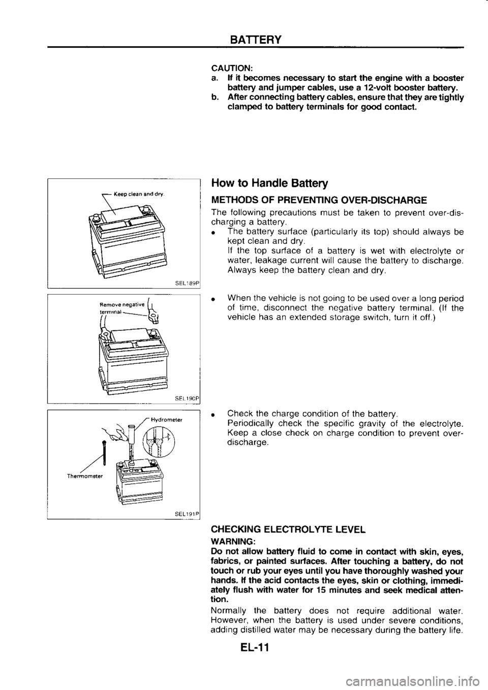
How to Handle
Battery
METHODS OF PREVENTING
OVER-DISCHARGE
The following precaulions
must be
taken to prevent
overdis-
charging a battery.
o The
battery surface (particularly
ils top) should always
be
kept clean and
dry.
lf the top surface of
a battery is
wet wilh electrolyte
or
water, leakage
current will cause the
battery to discharge.
Always keep
the battery
clean and dry.
When the vehicle is not going
to be used over a long period
ol time, disconnect the negative
battery terminal. (ll
the
vehicle has an extended storage
switch, turn it off.)
Check the charge
condition of the battery.
Periodically check the
specific gravity
of the
electrolyte.
Keep a close check
on charge condition
to prevent
over-
discharge.
CHECKING ELECTROLYTE
LEVEL
WARNING: Do not allow battery fluid
to come in contact with
skin, eyes,
fabrics, or painted
surfaces, After touching a
battery, do not
touch or rub your
eyes until you
have thoroughly washed your
hands. lf the
acid contacts the eyes,
skin or clothing, immedi-
ately flush with
water for 15 minutes
and seek medical atten-
tion.
Normally the
battery does not require
additional water.
However, when the
battery is used under severe
condilions,
adding distilled water may be necessary
during the battery life.
sEL
191
t
)
,r/ "
EL-11
Page 1138 of 1254

STARTING
SYSTEM -
Starter -
Assembly
Apply h igh-temperature grease
to lubricate
the bearing, gears
and frictional
surface when
assembling the starter.
Care{ully observe
the following inslructions.
Assembly at next
order:
. Gear
case
Pinion assembly and shift lever,
musl be mounted together.
. Ring
and pinion
shaft.
. (sR20DE)
Put the ball in
its hole.
o Field
coil and armature frame, must
be mounted
together.
Don't lock the holes of screws.
o Armature
f rame.
o Brush
holder.
Check the correct alignment of holes
of screws.
o Rear
cover.
. Magnetic
switch.
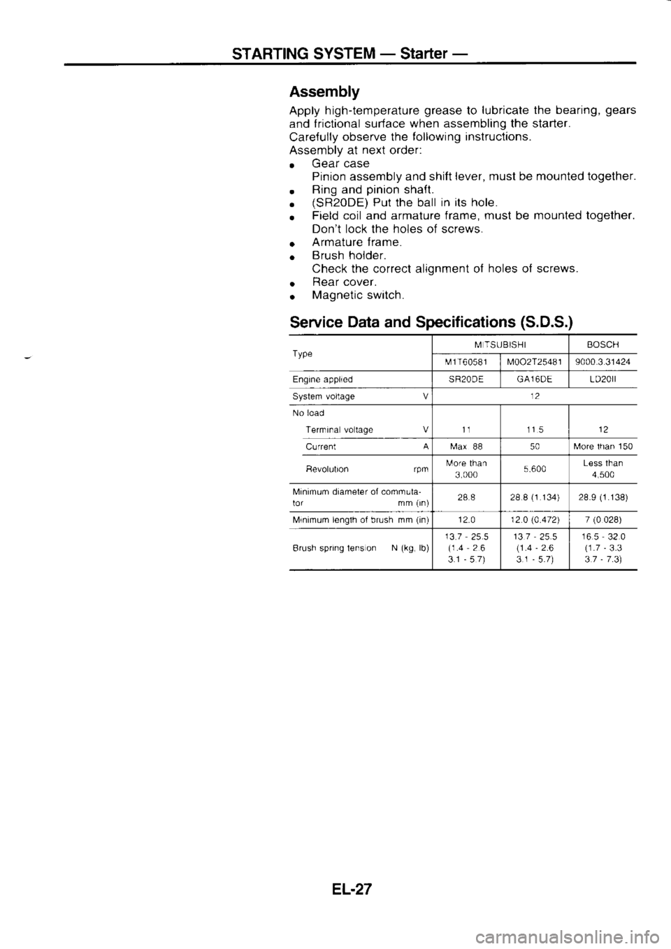
Service Data
and Specifications (S.D.S.)
Type M
TSUBISHI BOSCH
t\.rf 1 T6
05 8 I
M002T25481 9000.3
31424
Engine applied SR20DEGA16DE LD20rl
System voltage V 12
No load
Terrnrna voltage Vt1 115
Current A
[ra.x
88 50[,,lore
lhan 150
Bevolubon rpmtulore
than
3 000 5.600Less
than
4,500
Minimum diameter of comrnula-
lor mm (rn) 288
28 8 (1
134) 28.9 (1.138)
Mrnimum lenglh of brush mm (in)
12.0 12 0 (4.472)
7 (0
028)
Brush spring tens on N (kg,
lb) 13.7
25.5
(1.4 26
3.1 -57) 137
(1 .4
3.1 -
2.6 16.5
32.0
(1.7 -
3.3
3.7 -
7 .3)
EL.27
Page 1190 of 1254
WARNING
LAMPS AND
BUZZER
----](-
Continuity
Bsnery Diode
Check
o Check
continuity using an ohmmeter.
o Diode
is functioning properly
il test results are as shown in
the f
ioure
at left.
o Diodes
for warning lamps are built into the combination
meter orinted circuit.
Refer to "Combination
Meter".
Engine Oil Level Unit
Check
1 . Connect as shown in the figure at left.
2. lf test lamp comes on when disconnecting terminal
O from
battery ground,
engine oil level
unit is
normal.
Warning Buzer
Check
F \zz
fi*ffi=l
| | r:
rL----rr l
#/\
EL-79