1993 FORD MONDEO fuel tank removal
[x] Cancel search: fuel tank removalPage 105 of 279
the ring square to the tank and turning it at the
same time.
10Maintain the pressure while an assistant
refits and engages the retaining ring. When
the ring is engaged in the tank lugs, turn it
clockwise to tighten it until it is secured.
11The remainder of the refitting procedure is
the reverse of removal. Observe the colour-
coding to ensure that the fuel pipes are
reconnected to the correct unions.
Warning: The fuel system pressure
must be released before any part
of the system is disturbed - see
Section 2. Petrol is extremely
flammable, so take extra precautions when
you work on any part of the fuel system.
Don’t smoke, or allow open flames or bare
light bulbs, near the work area. Don’t work
in a garage where a natural gas-type
appliance (such as a water heater or clothes
dryer) with a pilot light is present. If you spill
any fuel on your skin, rinse it off
immediately with soap and water. When you
perform any kind of work on the fuel
system, wear safety glasses, and have a
Class B type fire extinguisher on hand.
1A fuel tank drain plug is not provided; it is
therefore preferable to carry out the removal
operation when the tank is nearly empty.
Before proceeding, disconnect the battery
negative (earth) lead, and syphon or hand-
pump the remaining fuel from the tank.
Alternatively, disconnect the feed pipe from
the fuel filter (see Chapter 1), and connect a
spare length of hose to this so that when the
ignition is switched on, the fuel pump will
empty the tank into a clean container. If this
approach is adopted, ensure that the
container is large enough to take all the fuel in
the tank, and be careful to take all suitable
precautions to prevent the risk of fire. Note:
Before disconnecting or opening any part of
the fuel system, relieve the residual pressure
(see Section 2), and equalise tank pressure by
removing the fuel filler cap. Also disconnect
the battery negative (earth) lead - see Chap-
ter 5, Section 1.2Unbolt or fold forwards (as appropriate) the
rear seat base cushion (see Chapter 11).
Withdraw from the vehicle’s floor the grommet
covering the fuel pump/sender unit. Unplug
the fuel pump/sender unit’s electrical
connector, and disconnect the fuel return pipe
(coded red) from the unit (see Section 9).
3Raise the rear of the vehicle, and support it
securely on axle stands. Get underneath and
familiarise yourself with the layout of the fuel
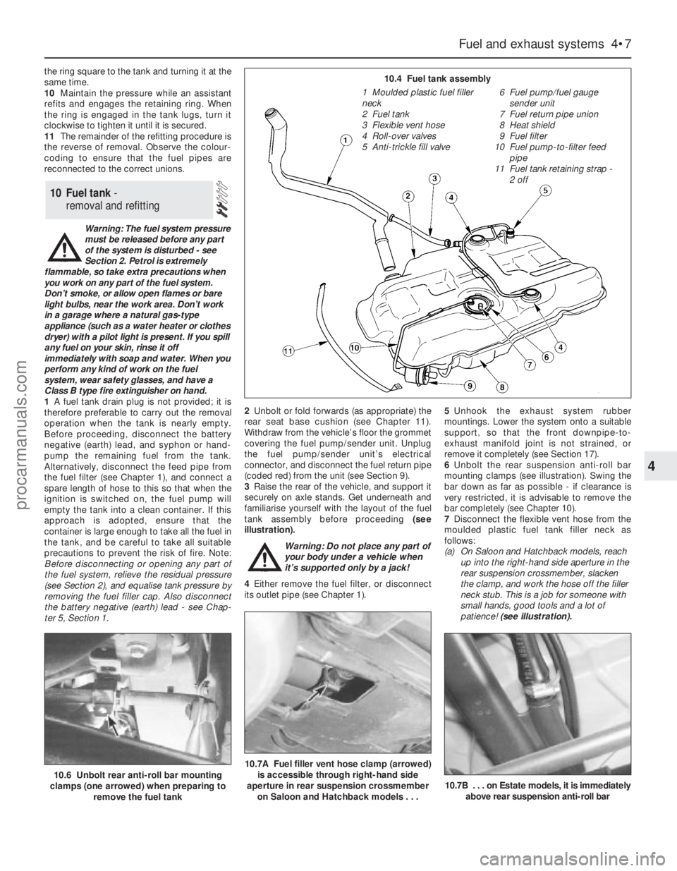
tank assembly before proceeding (see
illustration).
Warning: Do not place any part of
your body under a vehicle when
it’s supported only by a jack!
4Either remove the fuel filter, or disconnect
its outlet pipe (see Chapter 1).5Unhook the exhaust system rubber
mountings. Lower the system onto a suitable
support, so that the front downpipe-to-
exhaust manifold joint is not strained, or
remove it completely (see Section 17).
6Unbolt the rear suspension anti-roll bar
mounting clamps (see illustration). Swing the
bar down as far as possible - if clearance is
very restricted, it is advisable to remove the
bar completely (see Chapter 10).
7Disconnect the flexible vent hose from the
moulded plastic fuel tank filler neck as
follows:
(a) On Saloon and Hatchback models, reach
up into the right-hand side aperture in the
rear suspension crossmember, slacken
the clamp, and work the hose off the filler
neck stub. This is a job for someone with
small hands, good tools and a lot of
patience! (see illustration).
10 Fuel tank -
removal and refitting
Fuel and exhaust systems 4•7
4
10.6 Unbolt rear anti-roll bar mounting
clamps (one arrowed) when preparing to
remove the fuel tank10.7A Fuel filler vent hose clamp (arrowed)
is accessible through right-hand side
aperture in rear suspension crossmember
on Saloon and Hatchback models . . .
10.7B . . . on Estate models, it is immediately
above rear suspension anti-roll bar
10.4 Fuel tank assembly
1 Moulded plastic fuel filler
neck
2 Fuel tank
3 Flexible vent hose
4 Roll-over valves
5 Anti-trickle fill valve6 Fuel pump/fuel gauge
sender unit
7 Fuel return pipe union
8 Heat shield
9 Fuel filter
10 Fuel pump-to-filter feed
pipe
11 Fuel tank retaining strap -
2 off
procarmanuals.com
Page 106 of 279
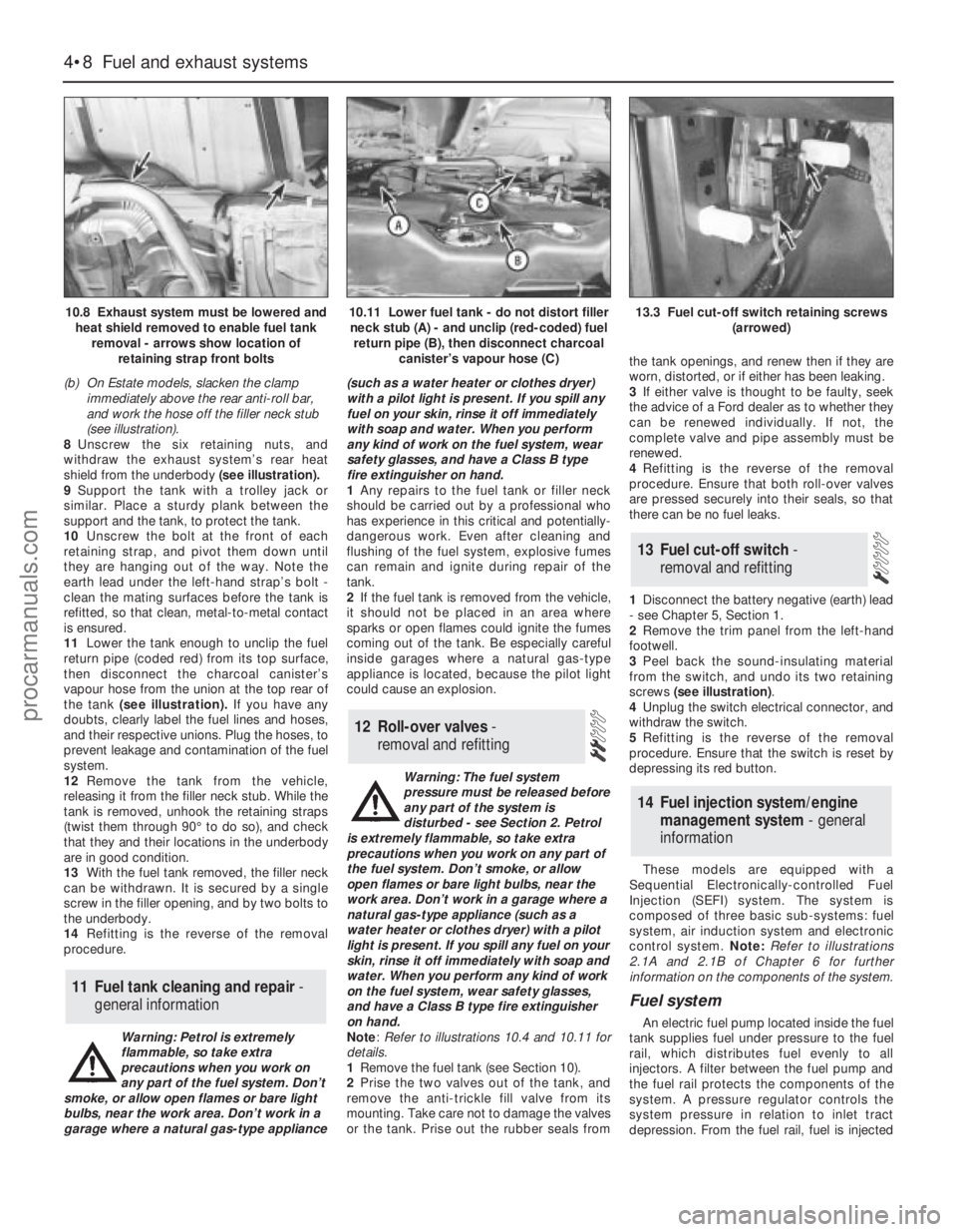
(b) On Estate models, slacken the clamp
immediately above the rear anti-roll bar,
and work the hose off the filler neck stub
(see illustration).
8Unscrew the six retaining nuts, and
withdraw the exhaust system’s rear heat
shield from the underbody (see illustration).
9Support the tank with a trolley jack or
similar. Place a sturdy plank between the
support and the tank, to protect the tank.
10Unscrew the bolt at the front of each
retaining strap, and pivot them down until
they are hanging out of the way. Note the
earth lead under the left-hand strap’s bolt -
clean the mating surfaces before the tank is
refitted, so that clean, metal-to-metal contact
is ensured.
11Lower the tank enough to unclip the fuel
return pipe (coded red) from its top surface,
then disconnect the charcoal canister’s
vapour hose from the union at the top rear of
the tank (see illustration). If you have any
doubts, clearly label the fuel lines and hoses,
and their respective unions. Plug the hoses, to
prevent leakage and contamination of the fuel
system.
12Remove the tank from the vehicle,
releasing it from the filler neck stub. While the
tank is removed, unhook the retaining straps
(twist them through 90° to do so), and check
that they and their locations in the underbody
are in good condition.
13With the fuel tank removed, the filler neck
can be withdrawn. It is secured by a single
screw in the filler opening, and by two bolts to
the underbody.
14Refitting is the reverse of the removal
procedure.
Warning: Petrol is extremely
flammable, so take extra
precautions when you work on
any part of the fuel system. Don’t
smoke, or allow open flames or bare light
bulbs, near the work area. Don’t work in a
garage where a natural gas-type appliance(such as a water heater or clothes dryer)
with a pilot light is present. If you spill any
fuel on your skin, rinse it off immediately
with soap and water. When you perform
any kind of work on the fuel system, wear
safety glasses, and have a Class B type
fire extinguisher on hand.
1Any repairs to the fuel tank or filler neck
should be carried out by a professional who
has experience in this critical and potentially-
dangerous work. Even after cleaning and
flushing of the fuel system, explosive fumes
can remain and ignite during repair of the
tank.
2If the fuel tank is removed from the vehicle,
it should not be placed in an area where
sparks or open flames could ignite the fumes
coming out of the tank. Be especially careful
inside garages where a natural gas-type
appliance is located, because the pilot light
could cause an explosion.
Warning: The fuel system
pressure must be released before
any part of the system is
disturbed - see Section 2. Petrol
is extremely flammable, so take extra
precautions when you work on any part of
the fuel system. Don’t smoke, or allow
open flames or bare light bulbs, near the
work area. Don’t work in a garage where a
natural gas-type appliance (such as a
water heater or clothes dryer) with a pilot
light is present. If you spill any fuel on your
skin, rinse it off immediately with soap and
water. When you perform any kind of work
on the fuel system, wear safety glasses,
and have a Class B type fire extinguisher
on hand.
Note: Refer to illustrations 10.4 and 10.11 for
details.
1Remove the fuel tank (see Section 10).
2Prise the two valves out of the tank, and
remove the anti-trickle fill valve from its
mounting. Take care not to damage the valves
or the tank. Prise out the rubber seals fromthe tank openings, and renew then if they are
worn, distorted, or if either has been leaking.
3If either valve is thought to be faulty, seek
the advice of a Ford dealer as to whether they
can be renewed individually. If not, the
complete valve and pipe assembly must be
renewed.
4Refitting is the reverse of the removal
procedure. Ensure that both roll-over valves
are pressed securely into their seals, so that
there can be no fuel leaks.
1Disconnect the battery negative (earth) lead
- see Chapter 5, Section 1.
2Remove the trim panel from the left-hand
footwell.
3Peel back the sound-insulating material
from the switch, and undo its two retaining
screws (see illustration).
4Unplug the switch electrical connector, and
withdraw the switch.
5Refitting is the reverse of the removal
procedure. Ensure that the switch is reset by
depressing its red button.
These models are equipped with a
Sequential Electronically-controlled Fuel
Injection (SEFI) system. The system is
composed of three basic sub-systems: fuel
system, air induction system and electronic
control system. Note:Refer to illustrations
2.1A and 2.1B of Chapter 6 for further
information on the components of the system.
Fuel system
An electric fuel pump located inside the fuel
tank supplies fuel under pressure to the fuel
rail, which distributes fuel evenly to all
injectors. A filter between the fuel pump and
the fuel rail protects the components of the
system. A pressure regulator controls the
system pressure in relation to inlet tract
depression. From the fuel rail, fuel is injected
14 Fuel injection system/engine
management system - general
information
13 Fuel cut-off switch -
removal and refitting
12 Roll-over valves -
removal and refitting
11 Fuel tank cleaning and repair -
general information
4•8 Fuel and exhaust systems
10.8 Exhaust system must be lowered and
heat shield removed to enable fuel tank
removal - arrows show location of
retaining strap front bolts10.11 Lower fuel tank - do not distort filler
neck stub (A) - and unclip (red-coded) fuel
return pipe (B), then disconnect charcoal
canister’s vapour hose (C)13.3 Fuel cut-off switch retaining screws
(arrowed)
procarmanuals.com
Page 108 of 279
Renewal
3Disconnect the battery negative (earth) lead
- see Chapter 5, Section 1.
4Remove the plenum chamber (see Sec-
tion 4).
5Disconnect the accelerator cable from the
throttle linkage (see Section 5 or 6, as
appropriate). Where fitted, also disconnect
the cruise control actuator cable (see Chap-
ter 12).
6Releasing its wire clip, unplug the large
electrical connector (next to the fuel pressure
regulator). Similarly release and unplug the
throttle potentiometer’s electrical connector.
7Clearly label, then detach, all vacuum hoses
from the throttle housing.
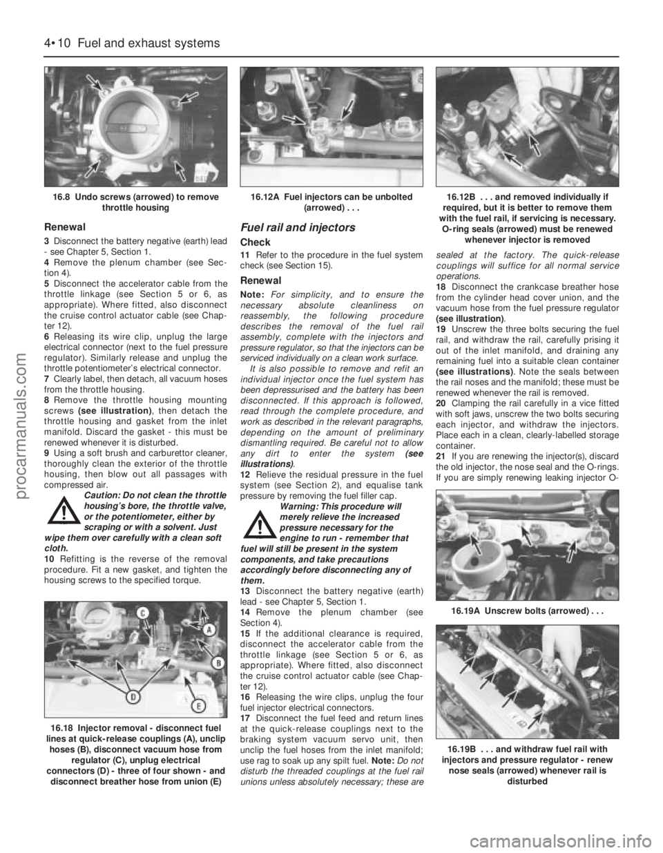
8Remove the throttle housing mounting
screws (see illustration), then detach the
throttle housing and gasket from the inlet
manifold. Discard the gasket - this must be
renewed whenever it is disturbed.
9Using a soft brush and carburettor cleaner,
thoroughly clean the exterior of the throttle
housing, then blow out all passages with
compressed air.
Caution: Do not clean the throttle
housing’s bore, the throttle valve,
or the potentiometer, either by
scraping or with a solvent. Just
wipe them over carefully with a clean soft
cloth.
10Refitting is the reverse of the removal
procedure. Fit a new gasket, and tighten the
housing screws to the specified torque.
Fuel rail and injectors
Check
11Refer to the procedure in the fuel system
check (see Section 15).
Renewal
Note:For simplicity, and to ensure the
necessary absolute cleanliness on
reassembly, the following procedure
describes the removal of the fuel rail
assembly, complete with the injectors and
pressure regulator, so that the injectors can be
serviced individually on a clean work surface.
It is also possible to remove and refit an
individual injector once the fuel system has
been depressurised and the battery has been
disconnected. If this approach is followed,
read through the complete procedure, and
work as described in the relevant paragraphs,
depending on the amount of preliminary
dismantling required. Be careful not to allow
any dirt to enter the system (see
illustrations).
12Relieve the residual pressure in the fuel
system (see Section 2), and equalise tank
pressure by removing the fuel filler cap.
Warning: This procedure will
merely relieve the increased
pressure necessary for the
engine to run - remember that
fuel will still be present in the system
components, and take precautions
accordingly before disconnecting any of
them.
13Disconnect the battery negative (earth)
lead - see Chapter 5, Section 1.
14Remove the plenum chamber (see
Section 4).
15If the additional clearance is required,
disconnect the accelerator cable from the
throttle linkage (see Section 5 or 6, as
appropriate). Where fitted, also disconnect
the cruise control actuator cable (see Chap-
ter 12).
16Releasing the wire clips, unplug the four
fuel injector electrical connectors.
17Disconnect the fuel feed and return lines
at the quick-release couplings next to the
braking system vacuum servo unit, then
unclip the fuel hoses from the inlet manifold;
use rag to soak up any spilt fuel. Note:Do not
disturb the threaded couplings at the fuel rail
unions unless absolutely necessary; these aresealed at the factory. The quick-release
couplings will suffice for all normal service
operations.
18Disconnect the crankcase breather hose
from the cylinder head cover union, and the
vacuum hose from the fuel pressure regulator
(see illustration).
19Unscrew the three bolts securing the fuel
rail, and withdraw the rail, carefully prising it
out of the inlet manifold, and draining any
remaining fuel into a suitable clean container
(see illustrations). Note the seals between
the rail noses and the manifold; these must be
renewed whenever the rail is removed.
20Clamping the rail carefully in a vice fitted
with soft jaws, unscrew the two bolts securing
each injector, and withdraw the injectors.
Place each in a clean, clearly-labelled storage
container.
21If you are renewing the injector(s), discard
the old injector, the nose seal and the O-rings.
If you are simply renewing leaking injector O-
4•10 Fuel and exhaust systems
16.8 Undo screws (arrowed) to remove
throttle housing16.12A Fuel injectors can be unbolted
(arrowed) . . .16.12B . . . and removed individually if
required, but it is better to remove them
with the fuel rail, if servicing is necessary.
O-ring seals (arrowed) must be renewed
whenever injector is removed
16.18 Injector removal - disconnect fuel
lines at quick-release couplings (A), unclip
hoses (B), disconnect vacuum hose from
regulator (C), unplug electrical
connectors (D) - three of four shown - and
disconnect breather hose from union (E)
16.19A Unscrew bolts (arrowed) . . .
16.19B . . . and withdraw fuel rail with
injectors and pressure regulator - renew
nose seals (arrowed) whenever rail is
disturbed
procarmanuals.com
Page 109 of 279
rings, and intend to re-use the same injectors,
remove the old nose seal and O-rings, and
discard them.
22Further testing of the injector(s) is beyond
the scope of the home mechanic. If you are in
doubt as to the status of any injector(s), it can
be tested at a dealer service department.
23Refitting is the reverse of the removal
procedure, noting the following points:
(a) Lubricate each nose seal and O-ring with
clean engine oil on installation.
(b) Locate each injector carefully in the fuel
rail recess, ensuring that the locating tab
on the injector head fits into the slot
provided in the rail. Tighten the bolts to
the specified torque.
(c) Fit a new seal to each fuel rail nose, and
ensure the seals are not displaced as the
rail is refitted. Ensure that the fuel rail is
settled fully in the manifold before
tightening the three bolts evenly and to
the torque wrench setting specified.
(d) Fasten the fuel feed and return quick-
release couplings as described in Sec-
tion 3.
(e) Ensure that the breather hose, vacuum
hose and wiring are routed correctly, and
secured on reconnection by any clips or
ties provided.
(f) On completion, switch the ignition on and
off five times, to activate the fuel pump and
pressurise the system, without cranking
the engine. Check for signs of fuel leaks
around all disturbed unions and joints
before attempting to start the engine.
Fuel pressure regulator
Check
24Refer to the fuel pump/fuel pressure
check procedure (see Section 8).
Renewal
25Relieve the residual pressure in the fuel
system (see Section 2), and equalise tank
pressure by removing the fuel filler cap.
Warning: This procedure will
merely relieve the increased
pressure necessary for the engine
to run - remember that fuel will
still be present in the system components,
and take precautions accordingly before
disconnecting any of them.26Disconnect the battery negative (earth)
lead - see Chapter 5, Section 1.
27Remove the plenum chamber (see
Section 4).
28Disconnect the vacuum hose from the
regulator.
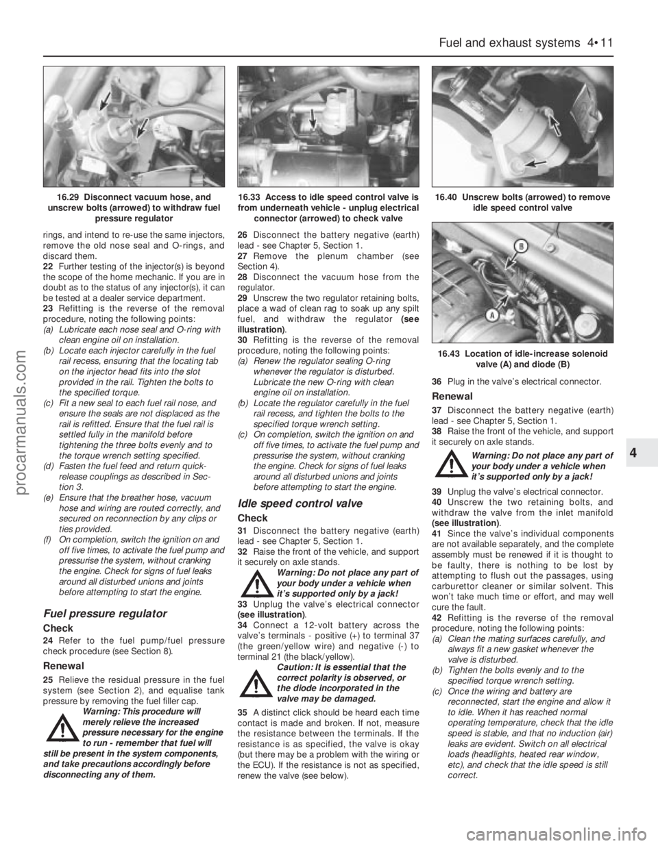
29Unscrew the two regulator retaining bolts,
place a wad of clean rag to soak up any spilt
fuel, and withdraw the regulator (see
illustration).
30Refitting is the reverse of the removal
procedure, noting the following points:
(a) Renew the regulator sealing O-ring
whenever the regulator is disturbed.
Lubricate the new O-ring with clean
engine oil on installation.
(b) Locate the regulator carefully in the fuel
rail recess, and tighten the bolts to the
specified torque wrench setting.
(c) On completion, switch the ignition on and
off five times, to activate the fuel pump and
pressurise the system, without cranking
the engine. Check for signs of fuel leaks
around all disturbed unions and joints
before attempting to start the engine.
Idle speed control valve
Check
31Disconnect the battery negative (earth)
lead - see Chapter 5, Section 1.
32Raise the front of the vehicle, and support
it securely on axle stands.
Warning: Do not place any part of
your body under a vehicle when
it’s supported only by a jack!
33Unplug the valve’s electrical connector
(see illustration).
34Connect a 12-volt battery across the
valve’s terminals - positive (+) to terminal 37
(the green/yellow wire) and negative (-) to
terminal 21 (the black/yellow).
Caution: It is essential that the
correct polarity is observed, or
the diode incorporated in the
valve may be damaged.
35A distinct click should be heard each time
contact is made and broken. If not, measure
the resistance between the terminals. If the
resistance is as specified, the valve is okay
(but there may be a problem with the wiring or
the ECU). If the resistance is not as specified,
renew the valve (see below).36Plug in the valve’s electrical connector.
Renewal
37Disconnect the battery negative (earth)
lead - see Chapter 5, Section 1.
38Raise the front of the vehicle, and support
it securely on axle stands.
Warning: Do not place any part of
your body under a vehicle when
it’s supported only by a jack!
39Unplug the valve’s electrical connector.
40Unscrew the two retaining bolts, and
withdraw the valve from the inlet manifold
(see illustration).
41Since the valve’s individual components
are not available separately, and the complete
assembly must be renewed if it is thought to
be faulty, there is nothing to be lost by
attempting to flush out the passages, using
carburettor cleaner or similar solvent. This
won’t take much time or effort, and may well
cure the fault.
42Refitting is the reverse of the removal
procedure, noting the following points:
(a) Clean the mating surfaces carefully, and
always fit a new gasket whenever the
valve is disturbed.
(b) Tighten the bolts evenly and to the
specified torque wrench setting.
(c) Once the wiring and battery are
reconnected, start the engine and allow it
to idle. When it has reached normal
operating temperature, check that the idle
speed is stable, and that no induction (air)
leaks are evident. Switch on all electrical
loads (headlights, heated rear window,
etc), and check that the idle speed is still
correct.
Fuel and exhaust systems 4•11
4
16.43 Location of idle-increase solenoid
valve (A) and diode (B)
16.29 Disconnect vacuum hose, and
unscrew bolts (arrowed) to withdraw fuel
pressure regulator16.33 Access to idle speed control valve is
from underneath vehicle - unplug electrical
connector (arrowed) to check valve16.40 Unscrew bolts (arrowed) to remove
idle speed control valve
procarmanuals.com
Page 138 of 279
constantly monitors the oxygen content of the
exhaust gas. If the percentage of oxygen in
the exhaust gas is incorrect, an electrical
signal is sent to the ECU. The ECU processes
this information, and then sends a command
to the fuel injection system, telling it to change
the air/fuel mixture; the end result is an air/fuel
mixture ratio which is constantly maintained
at a predetermined ratio, regardless of driving
conditions. This happens in a fraction of a
second, and goes on almost all the time while
the engine is running - the exceptions are that
the ECU cuts out the system and runs the
engine on values pre-programmed
(“mapped”) into its memory both while the
oxygen sensor is reaching its normal
operating temperature after the engine has
been started from cold, and when the throttle
is fully open for full acceleration.
In the event of a sensor malfunction, a
back-up circuit will take over, to provide
driveability until the problem is identified and
fixed.
Precautions
(a) Always disconnect the power by
uncoupling the battery terminals - see
Section 1 of Chapter 5 - before removing
any of the electronic control system’s
electrical connectors.
(b) When installing a battery, be particularly
careful to avoid reversing the positive and
negative battery leads.
(c) Do not subject any components of the
system (especially the ECU) to severe
impact during removal or installation.
(d) Do not be careless during fault diagnosis.
Even slight terminal contact can invalidate
a testing procedure, and damage one of
the numerous transistor circuits.
(e) Never attempt to work on the ECU, to test
it (with any kind of test equipment), or to
open its cover.
(f) If you are inspecting electronic control
system components during rainy weather,
make sure that water does not enter any
part. When washing the engine
compartment, do not spray these parts or
their electrical connectors with water.
General
The various components of the fuel, ignition
and emissions control systems (not forgetting
the same ECU’s control of sub-systems such
as the radiator cooling fan, air conditioning
and automatic transmission, where
appropriate) are so closely interlinked that
diagnosis of a fault in any one component is
virtually impossible using traditional methods.
Working on simpler systems in the past, the
experienced mechanic may well have been
able to use personal skill and knowledge
immediately to pinpoint the cause of a fault, or
quickly to isolate the fault, by elimination;however, with an engine management system
integrated to this degree, this is not likely to
be possible in most instances, because of the
number of symptoms that could arise from
even a minor fault.
So that the causes of faults can be quickly
and accurately traced and rectified, the ECU
is provided with a built-in self-diagnosis
facility, which detects malfunctions in the
system’s components. When a fault occurs,
three things happen: the ECU identifies the
fault, stores a corresponding code in its
memory, and (in most cases) runs the system
using back-up values pre-programmed
(“mapped”) into its memory; some form of
driveability is thus maintained, to enable the
vehicle to be driven to a garage for attention.
Any faults that may have occurred are
indicated in the form of three-digit codes
when the system is connected (via the built-in
diagnosis or self-test connectors, as
appropriate) to special diagnostic equipment -
this points the user in the direction of the
faulty circuit, so that further tests can pinpoint
the exact location of the fault.
Given below is the procedure that would be
followed by a Ford technician to trace a fault
from scratch. Should your vehicle’s engine
management system develop a fault, read
through the procedure and decide how much
you can attempt, depending on your skill and
experience and the equipment available to
you, or whether it would be simpler to have
the vehicle attended to by your local Ford
dealer. If you are concerned about the
apparent complexity of the system, however,
remember the comments made in the fourth
paragraph of Section 1 of this Chapter; the
preliminary checks require nothing but care,
patience and a few minor items of equipment,
and may well eliminate the majority of faults.
(a) Preliminary checks
(b) Fault code read-out *
(c) Check ignition timing and base idle
speed. Recheck fault codes to establish
whether fault has been cured or not *
(d) Carry out basic check of ignition system
components. Recheck fault codes to
establish whether fault has been cured or
not *
(e) Carry out basic check of fuel system
components. Recheck fault codes to
establish whether fault has been cured or
not *
(f) If fault is still not located, carry out system
test *
Note:Operations marked with an asterisk
require special test equipment.
Preliminary checks
Note:When carrying out these checks to
trace a fault, remember that if the fault has
appeared only a short time after any part of
the vehicle has been serviced or overhauled,
the first place to check is where that work was
carried out, however unrelated it may appear,
to ensure that no carelessly-refitted
components are causing the problem.If you are tracing the cause of a “partial”
engine fault, such as lack of performance, in
addition to the checks outlined below, check
the compression pressures (see Part A of
Chapter 2) and bear in mind the possibility
that one of the hydraulic tappets might be
faulty, producing an incorrect valve clearance.
Check also that the fuel filter has been
renewed at the recommended intervals.
If the system appears completely dead,
remember the possibility that the
alarm/inhibitor system may be responsible.
1The first check for anyone without special
test equipment is to switch on the ignition,
and to listen for the fuel pump (the sound of
an electric motor running, audible from
beneath the rear seats); assuming there is
sufficient fuel in the tank, the pump should
start and run for approximately one or two
seconds, then stop, each time the ignition is
switched on. If the pump runs continuously all
the time the ignition is switched on, the
electronic control system is running in the
back-up (or “limp-home”) mode referred to by
Ford as “Limited Operation Strategy” (LOS).
This almost certainly indicates a fault in the
ECU itself, and the vehicle should therefore be
taken to a Ford dealer for a full test of the
complete system using the correct diagnostic
equipment; do not waste time trying to test
the system without such facilities.
2If the fuel pump is working correctly (or not
at all), a considerable amount of fault
diagnosis is still possible without special test
equipment. Start the checking procedure as
follows.
3Open the bonnet and check the condition
of the battery connections - remake the
connections or renew the leads if a fault is
found (Chapter 5). Use the same techniques
to ensure that all earth points in the engine
compartment provide good electrical contact
through clean, metal-to-metal joints, and that
all are securely fastened. (In addition to the
earth connection at the engine lifting eye and
that from the transmission to the
body/battery, there is one earth connection
behind each headlight assembly, and one
below the power steering fluid reservoir.)
4Referring to the information given in
Chapter 12 and in the wiring diagrams at the
back of this manual, check that all fuses
protecting the circuits related to the engine
management system are in good condition.
Fit new fuses if required; while you are there,
check that all relays are securely plugged into
their sockets.
5Next work methodically around the engine
compartment, checking all visible wiring, and
the connections between sections of the
wiring loom. What you are looking for at this
stage is wiring that is obviously damaged by
chafing against sharp edges, or against
moving suspension/transmission components
and/or the auxiliary drivebelt, by being
trapped or crushed between carelessly-
refitted components, or melted by being
forced into contact with hot engine castings,
3 Diagnosis system -
general information
6•4 Emissions control systems
procarmanuals.com
Page 148 of 279
(where fitted) and renew it if it is damaged or
worn. Apply a smear of anti-seize compound
to the sensor’s threads, to prevent them from
welding themselves to the downpipe in
service. Refit the sensor, tightening it to its
specified torque wrench setting; a slotted
socket will be required to do this (see
illustration). Reconnect the wiring and refit
the connector plug.
General description
1This system is fitted to minimise the escape
of unburned hydrocarbons into the
atmosphere. The fuel tank filler cap is sealed,
and a charcoal canister is mounted
underneath the tank, to collect and store
petrol vapours generated in the tank when the
vehicle is parked. When the engine is running,
the vapours are cleared from the canister
(under the control of the ECU via the canister-
purge solenoid valve) into the inlet tract, to be
burned by the engine during normal
combustion - see illustration 2.1A.
2To ensure that the engine runs correctly
when it is cold and/or idling, and to protect
the catalytic converter from the effects of an
over-rich mixture, the canister-purge solenoid
valve is not opened by the ECU until the
engine is fully warmed-up and running under
part-load; the solenoid valve is then switched
on and off, to allow the stored vapour to pass
into the inlet.
Checking
3Poor idle, stalling and poor driveability can
be caused by an inoperative canister-purge
solenoid valve, a damaged canister, split or
cracked hoses, or hoses connected to the
wrong fittings. Check the fuel filler cap for a
damaged or deformed gasket.
4Fuel loss or fuel odour can be caused by
liquid fuel leaking from fuel lines, a cracked or
damaged canister, an inoperative canister-purge solenoid valve, and disconnected,
misrouted, kinked or damaged vapour or
control hoses.
5Inspect each hose attached to the canister
for kinks, leaks and cracks along its entire
length. Repair or renew as necessary.
6Inspect the canister. If it is cracked or
damaged, renew it. Look for fuel leaking from
the bottom of the canister. If fuel is leaking,
renew the canister, and check the hoses and
hose routing.
7If the canister-purge solenoid valve is
thought to be faulty, unplug its electrical
connector and disconnect its vacuum hoses.
Connect a battery directly across the valve
terminals. Check that air can flow through the
valve passages when the solenoid is thus
energised, and that nothing can pass when the
solenoid is not energised. Alternatively,
connect an ohmmeter to measure the
resistance across the solenoid terminals, and
compare this reading to the one listed in the
Specifications Section at the beginning of this
Chapter. Renew the solenoid valve if it is faulty.
8Further testing should be left to a dealer
service department.
Component renewal
Charcoal canister-purge solenoid
valve
9If better access is required, remove the
plenum chamber (see Chapter 4). Disconnect
the battery negative (earth) lead - see Sec-
tion 1 of Chapter 5.10Unplug the valve’s electrical connector
(see illustration). Unclip the valve from the
bulkhead, then disconnect its vacuum hoses
and withdraw it.
11Refitting is the reverse of the removal
procedure.
Charcoal canister - Saloon and
Hatchback models
Note:Read through this procedure carefully
before starting work, and ensure that the
equipment is available that is required to carry
it out safely and with minimum risk of damage,
and to align the crossmember with sufficient
accuracy on reassembly.
12Remove the fuel tank (see Chapter 4).
13Ensure that the rear of the vehicle’s body
is supported securely on axle stands, then
support the rear suspension crossmember
with a jack. Remove the roadwheels and
unscrew the rear suspension strut top
mounting bolts (two per side - see Chapter
10).
14Use white paint or similar (do not use a
sharp-pointed scriber, which might break the
underbody protective coating and cause
rusting) to mark the exact relationship of the
crossmember to the underbody. Unscrew the
four mounting bolts (see illustration). Lower
the crossmember approximately 3 inches (75
mm) on the jack, and support it securely.
Warning: DO NOT place any part
of your body under the vehicle
when it is supported only by a
jack!
5 EVAPorative emissions control
(EVAP) system -
general information, checking
and component renewal
6•14 Emissions control systems
4.64 . . . slotted socket will be required to
tighten sensor with a torque wrench5.10 Charcoal canister-purge solenoid
valve (arrowed) is clipped to bulkhead
behind engine5.14 Support rear suspension
crossmember on jack, and remove
mounting bolts (arrowed) . . .
5.15 . . . lower crossmember by 3 inches,
and unscrew charcoal canister assembly
rear retaining bolts (arrowed) . . .5.16 . . . unplug hoses (arrowed) from
canister assembly . . .
procarmanuals.com
Page 167 of 279
3Unscrew the bolts securing the anti-roll bar
mounting clamps to the rear suspension
crossmember, then unhook the clamps and
withdraw the anti-roll bar from under the
vehicle (see illustration).
4Examine the rubber bushes for the
mounting clamps and links, and if necessary
renew them. The links are available
individually.
Refitting
5Locate the anti-roll bar on the rear
crossmember, hook the mounting clamps in
position, and insert the bolts. Tighten the
bolts to the specified torque.
6Locate the anti-roll bar links in the front
lower arms on both sides, making sure that
the rubber bushes are in position. Refit the
nuts and tighten them to the specified torque.
7Refit the rear wheels, and lower the vehicle
to the ground.
Removal
1Chock the front wheels, then jack up the
rear of the vehicle and support it on axle
stands. Remove the appropriate rear wheel.
Front lower arm
2To remove the front lower arm, it is
necessary to remove the fuel tank first. Refer
to Chapter 4 for details.
3Unscrew the nut and disconnect the anti-
roll bar link from the lower arm. Hold the
actual link with an adjustable spanner or grips
while unscrewing the nut, to prevent damage
to the link joint. Recover the rubber bush.
4Unscrew and remove the bolt securing the
front lower arm to the knuckle.
5Unscrew and remove the bolt securing the
front lower arm to the crossmember.
6Withdraw the front lower arm from under
the vehicle.
Rear lower arm
7Unscrew and remove the bolt securing the
rear lower arm to the knuckle.8The bolt securing the rear lower arm to the
crossmember has an eccentric head and
spacer, which are used to adjust the rear toe
setting. Before removing this bolt, mark its
position, using a scriber or similar sharp
instrument through the aperture in the
crossmember.
9Unscrew and remove the bolt securing the
rear lower arm to the crossmember (see
illustration). The bolt may be removed
through the aperture in the crossmember.
Recover the eccentric spacer.
10Withdraw the rear lower arm from under
the vehicle.
Refitting
11Refitting is a reversal of the removal
procedure, but the arm mounting bolts should
be finger-tightened initially, and only fully
tightened after the vehicle is lowered to the
ground, so that its weight is on the rear
suspension. Note that the rear lower arm is
marked “TOP” for correct refitting (see
illustration). The rear toe setting should be
checked, and if necessary adjusted, at the
earliest opportunity.
Removal
1Chock the front wheels, then jack up the
rear of the vehicle and support it on axle
stands. Remove the appropriate rear wheel.
2Disconnect the handbrake cable from the
tie-bar bracket on the underbody.
3Unscrew and remove the bolt securing the
tie-bar bracket to the rear suspension
knuckle.
4Unscrew the bolts securing the tie-bar
bracket to the underbody, and withdraw the
bracket from the vehicle (see illustration).
5Mount the bracket in a vice, then unscrew
and remove the bolt, and remove the tie-bar
from the bracket.
6It is not possible to renew the rubber
bushes - if they are worn excessively, the tie-
bar should be renewed complete.
Refitting
7Refitting is a reversal of the removal
procedure. The bracket-to-underbody bolts
should be fully tightened to the specified
torque before lowering the vehicle. The bolts
securing the tie-bar to the bracket and
knuckle should be finger-tightened initially,
and only fully tightened after the vehicle is
lowered to the ground, so that its weight is on
the rear suspension.
Note:Before attempting to remove the rear
suspension crossmember, tools to hold the
coil springs in compression must be obtained.
Careful use of conventional coil spring
compressors will prove satisfactory.
Removal
1Chock the front wheels, then jack up the
rear of the vehicle and support it on axle
stands. Remove both rear wheels.
2Remove the complete exhaust system as
described in Chapter 4.
3Unscrew and remove the bolts securing the
tie-bars to the rear suspension knuckles, and
disconnect the tie-bars.
4Unscrew the nuts securing the rear anti-roll
bar links to the front lower arms. Hold the
16 Rear suspension
crossmember
(Saloon/Hatchback models) -
removal and refitting
15 Rear suspension tie-bar
(Saloon/Hatchback models) -
removal and refitting
14 Rear suspension lower arms
(Saloon/Hatchback models)-
removal and refitting
Suspension and steering systems 10•13
10
14.11 “TOP” marking on the rear lower
arm
15.4 Tie-bar bracket on the underbody
13.3 Rear anti-roll bar mounting clamp14.9 Bolt securing the rear lower arm to
the crossmember
procarmanuals.com
Page 214 of 279
located above the front direction indicator
(see illustration).
11Withdraw the front direction indicator light
unit.
12Rotate the bulbholder anti-clockwise, and
withdraw it from the light unit. Alternatively,
the wiring plug can be disconnected from the
bulbholder, leaving the bulb in position (see
illustration). Remove the light unit.
Foglight (front)
13Unscrew the cross-head screws securing
the front foglight unit to the valance, and
withdraw the light unit from the valance.
14Prise open the plastic clips, and remove
the rear cover from the light unit.
15Release the spring clips and withdraw the
bulb, then pull off the wiring connector.
Remove the foglight unit.
Rear light cluster
16With the tailgate or bootlid open, unhook
the parcel net (where fitted) from the rear of
the luggage compartment.
17On Saloon and Hatchback models,
remove the screws, release the clips, and
remove the trim panel from the rear cross
panel. On Estate models, it is sufficient to
open the flap.
18Remove the screws, and press the rear
light trim cover from the guides (where
applicable).
19Disconnect the wiring multi-plug.
20Unscrew the four mounting nuts, and
withdraw the light unit from the outside of the
vehicle (see illustrations).
Rear number plate light assembly
21Remove both number plate lights as
described in Section 5.
22With the tailgate or bootlid open, remove
the screws and withdraw the inner trim panel.
23Unscrew the nuts, and remove the outer
cover and number plate base from the
tailgate.
24Disconnect the multi-plug and remove the
light assembly.
Refitting
25Refitting of all the external light units is a
reversal of the removal procedure, noting the
following points:(a) When refitting the rubber seal on the
headlight unit, note that it has a tapered
seat.
(b) If one or both headlights have been
disturbed, have the beam alignment
checked as described in the next Section.
(c) When refitting the rear light cluster, check
the condition of the sealer on the body
panel, and if necessary renew it.
1Accurate adjustment of the headlight beam
is only possible using optical beam-setting
equipment. This work should therefore be
carried out by a Ford dealer, or other service
station with the necessary facilities.
2Temporary adjustment can be made after
renewal of a headlight bulb or unit, or as an
emergency measure if the alignment is
incorrect following accident damage. Turn the
adjustment screws on the top of the headlamp
unit to make the adjustment (see illustration).
3Before making any adjustments to the
settings, it is important that the tyre pressures
are correct, and that the vehicle is standing on
level ground. Bounce the front of the vehicle a
few times to settle the suspension. Ideally,
somebody of average size should sit in the
driver’s seat during the adjustment, and the
vehicle should have a full tank of fuel. Where a
vehicle is fitted with an electrical beam
levelling system, set the switch to the “O”
position before making any adjustments.4Whenever temporary adjustments are
made, the settings must be checked and if
necessary reset by a Ford dealer or other
qualified person as soon as possible.
Removal
1Remove the headlight unit as described in
Section 7, then remove the cover.
2Disconnect the wiring multi-plug from the
motor.
3Rotate the motor upwards approximately
60°, then pull it forwards slightly.
4Disconnect the adjustment spindle by
pressing the ball coupling to one side, away
from the socket on the reflector.
5Withdraw the motor from the headlight unit.
Refitting
6Refitting is a reversal of the removal
procedure, but make sure that the motor is
turned down until it engages the stop.
Removal
1Disconnect the battery negative (earth) lead
(refer to Chapter 5, Section 1).
10 Instrument panel -
removal and refitting
9 Headlight levelling motor -
removal and refitting
8 Headlight beam alignment-
checking and adjustment
Body electrical system 12•13
12
7.20B Removing the rear light cluster unit
8.2 Headlight beam setting adjustment
screws
1 Vertical alignment screw
2 Horizontal alignment screw
7.10 Loosen the front direction indicator
retaining screw7.12 Disconnecting the wiring plug from
the indicator bulbholder7.20A Rear light cluster mounting nuts
(arrowed)
procarmanuals.com