1993 CHEVROLET PLYMOUTH ACCLAIM ac refrigerant
[x] Cancel search: ac refrigerantPage 31 of 2438
COMPONENT AND SYSTEM INDEX
Name Group-page Name Group-page
BODY ................................... 23-1
AA-VEHICLE BODY COMPONENT SERVICE .......23-11
AC-VEHICLE BODY COMPONENT SERVICE .......23-37
AG-VEHICLE BODY COMPONENT SERVICE .......23-52
AJ/27-VEHICLE CONVERTIBLE BODY COMPONENT SERVICE ............................ 23-86
AJ-VEHICLE BODY COMPONENT SERVICE .......23-71
AP-VEHICLE BODY COMPONENT SERVICE .......23-97
AY-VEHICLE BODY COMPONENT SERVICE .......23-133
BODY DIAGNOSTIC PROCEDURES .............23-2
GENERAL SERVICE INFORMATION .............23-1
PAINT ................................. 23-4
POWER SUNROOF ........................ 23-6
WINDSHIELD ............................ 23-9
BRAKES ..................................5-1
ANTI-LOCK BRAKE SYSTEMÐBENDIX ANTI-LOCK 10 AC/Y BODY ......................... 5-72
ANTI-LOCK BRAKE SYSTEMÐBENDIX ANTI-LOCK 6 AA,AG,AJ,AP BODY .................... 5-113
BRAKE DISC (ROTOR) ...................... 5-53
BRAKE SUPPORT ASSEMBLY .................5-25
FRONT DISC BRAKES ...................... 5-31
GENERAL INFORMATION .....................5-1
HYDRAULIC SYSTEM CONTROL VALVES .........5-26
KELSEY HAYES DOUBLE PIN FAMILY CALIPER .....5-35
KELSEY HAYES DOUBLE PIN NON-FAMILY CALIPER ............................. 5-38
MASTER CYLINDER ....................... 5-66
PARKING BRAKES ........................ 5-57
POWER BRAKES ......................... 5-68
REAR DISC BRAKES ....................... 5-45
REAR WHEEL DRUM BRAKES ................5-18
SERVICE ADJUSTMENTS .....................5-4
WHEEL BEARINGS ........................ 5-70
WHEEL CYLINDERS ....................... 5-23
COOLING SYSTEM ...........................7-1
ACCESSORY DRIVE BELTS ................... 7-24
ENGINE BLOCK HEATER .................... 7-28
GENERAL INFORMATION .....................7-1
SERVICE PROCEDURES ..................... 7-10
SPECIFICATIONS ......................... 7-29
ENGINE ..................................9-1
2.2/2.5L ENGINES .........................9-8
3.0L ENGINE ............................ 9-66
3.3/3.8L ENGINE ......................... 9-98
STANDARD SERVICE PROCEDURES .............9-1
EXHAUST SYSTEM AND INTAKE MANIFOLD .........11-1
GENERAL INFORMATION .................... 11-1
SERVICE PROCEDURES ..................... 11-4
TORQUE SPECIFICATION ................... 11-25
FRAME AND BUMPERS ....................... 13-1
BUMPER AND FASCIA ...................... 13-1
FRAME ................................ 13-9
HEATING AND AIR CONDITIONING ...............24-1
AUTOMATIC TEMPERATURE CONTROL (ATC) .....24-66 COMPONENT SERVICE PROCEDURES
..........24-47
FIXED DISPLACEMENT COMPRESSORÐMODEL 10PA17............................. 24-24
FIXED DISPLACEMENT COMPRESSORÐMODEL SD709P ............................. 24-38
FIXED DISPLACEMENT COMPRESSORÐMODEL TR105 .............................. 24-32
GENERAL INFORMATION .................... 24-1
HEATER AND A/C PERFORMANCE TESTS .........24-6
REFRIGERANT SERVICE PROCEDURES ..........24-8
VACUUM CONTROL SYSTEM DIAGNOSIS .........24-4
VARIABLE DISPLACEMENT COMPRESSORÐMODEL 6C17 ............................... 24-13
INTRODUCTION .......................... Intro.-1
LUBRICATION AND MAINTENANCE ................0-1
CHASSIS AND BODY ....................... 0-19
DRIVETRAIN ............................ 0-16
ENGINE ................................0-8
GENERAL INFORMATION .....................0-1
MANUAL TRANSAXLE CLUTCH ...................6-1
STEERING ................................ 19-1
ACUSTAR STANDARD AND TILT STEERING COLUMN ............................ 19-28
AUTOMATIC TRANSMISSION SHIFTER/IGNITION INTERLOCK .......................... 19-36
GENERAL INFORMATION .................... 19-1
POWER STEERING GEAR ................... 19-25
POWER STEERING PUMPS ..................19-1
SPECIFICATIONS AND TIGHTENING REFERENCE . . . 19-42
SUSPENSION AND DRIVESHAFTS .................2-1
AUTOMATIC AIR LOAD LEVELING SYSTEM ........2-59
AUTOMATIC AIR SUSPENSION ................2-73
DRIVESHAFTS ........................... 2-25
FRONT SUSPENSION .......................2-2
FRONT SUSPENSION SERVICE PROCEDURES .......2-5
GENERAL INFORMATION .....................2-1
REAR (STUB) AXLE ALIGNMENT ALL MODELS .....2-89
REAR SUSPENSION ....................... 2-50
SPECIFICATIONS ......................... 2-91
TRANSAXLE .............................. 21-85
41TE FOUR SPEED AUTOMATIC TRANSAXLE ......21-85
41TE FOUR SPEED TRANSAXLE HYDRAULIC SCHEMATICS ........................ 21-170
41TE ON-BOARD DIAGNOSTICS .............21-145
A-523, A-543, and A-568 MANUAL TRANSAXLE ....21-1
SPECIFICATIONS ........................ 21-183
THREE SPEED TORQUEFLITE AUTOMATIC TRANSAXLE .......................... 21-35
THREE SPEED TRANSAXLE HYDRAULIC SCHEMATICS ........................ 21-162
WHEELSÐTIRES ........................... 22-1
SPECIFICATIONS ......................... 22-8
TIRE SERVICE PROCEDURES .................22-1
WHEELS SERVICE PROCEDURES ..............22-6
Page 411 of 2438
GENERATOR INDEX
page page
General Information ........................ 9
Generator ReplacementÐ2.2L Turbo Engine (With 16 Valve Cylinder Head) ............. 10 Generator ReplacementÐ2.2L/2.5L Engine
...... 9
Generator ReplacementÐ3.0L Engine ......... 10
Generator ReplacementÐ3.3L/3.8L Engine ..... 11
GENERAL INFORMATION
This section will cover generator removal and instal-
lation only. Information covering generator on-vehicle
testing and diagnosis can be found in Group 8A,
Battery/Starting/Charging Systems Diagnostics. To
identify the generator, refer to the Generator Specifi-
cation chart at the rear of this section. These generators are not intended to be disas-
sembled for service. It must be replaced as an
assembly.
GENERATOR REPLACEMENTÐ2.2L/2.5L ENGINE
Removal and repositioning of A/C compressor (with-
out disconnecting refrigerant lines) is necessary on
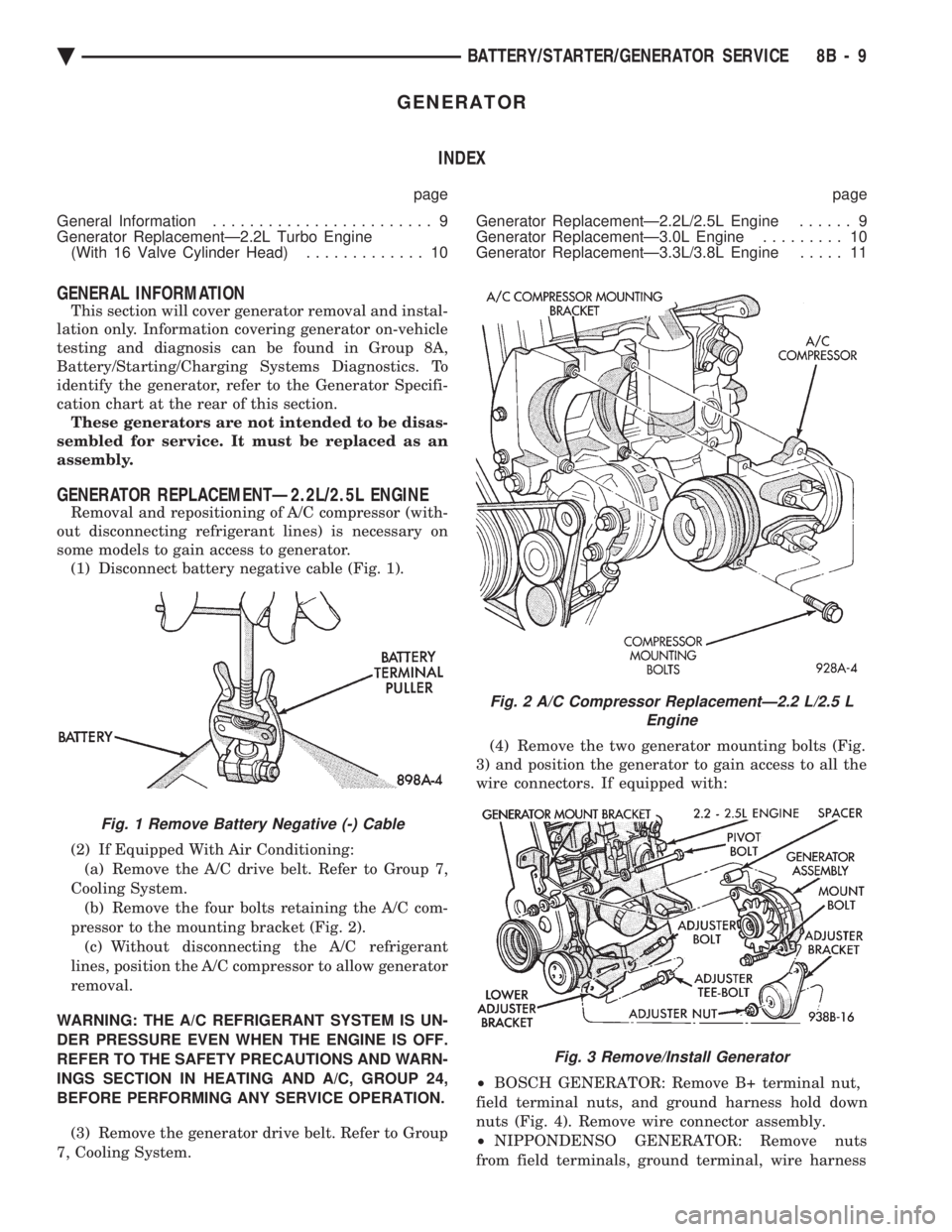
some models to gain access to generator. (1) Disconnect battery negative cable (Fig. 1).
(2) If Equipped With Air Conditioning:
(a) Remove the A/C drive belt. Refer to Group 7,
Cooling System. (b) Remove the four bolts retaining the A/C com-
pressor to the mounting bracket (Fig. 2). (c) Without disconnecting the A/C refrigerant
lines, position the A/C compressor to allow generator
removal.
WARNING: THE A/C REFRIGERANT SYSTEM IS UN-
DER PRESSURE EVEN WHEN THE ENGINE IS OFF.
REFER TO THE SAFETY PRECAUTIONS AND WARN-
INGS SECTION IN HEATING AND A/C, GROUP 24,
BEFORE PERFORMING ANY SERVICE OPERATION. (3) Remove the generator drive belt. Refer to Group
7, Cooling System. (4) Remove the two generator mounting bolts (Fig.
3) and position the generator to gain access to all the
wire connectors. If equipped with:
² BOSCH GENERATOR: Remove B+ terminal nut,
field terminal nuts, and ground harness hold down
nuts (Fig. 4). Remove wire connector assembly.
² NIPPONDENSO GENERATOR: Remove nuts
from field terminals, ground terminal, wire harness
Fig. 1 Remove Battery Negative (-) Cable
Fig. 2 A/C Compressor ReplacementÐ2.2 L/2.5 L Engine
Fig. 3 Remove/Install Generator
Ä BATTERY/STARTER/GENERATOR SERVICE 8B - 9
Page 412 of 2438

and B+ terminal (Fig. 5). B+ terminal nut must be
removed last to prevent damage to terminal insula-
tor. (5) Remove the generator from the vehicle.
(6) For installation, reverse above procedures.
Tighten all fasteners to the proper torque. Refer to
the Torque Specifications chart at the rear of this
group.
GENERATOR REPLACEMENTÐ2.2L TURBO
ENGINE (WITH 16 VALVE CYLINDER HEAD)
(1) Disconnect battery NEGATIVE cable (Fig. 1).
(2) Remove generator/air conditioning drive belt.
Refer to Group 7, Cooling System. (3) Remove the bolts retaining the A/C compressor
to the mounting bracket. (4) Without disconnecting the A/C refrigerant
lines, position the A/C compressor to allow generator
removal. WARNING: THE A/C REFRIGERANT SYSTEM IS UN-
DER PRESSURE EVEN WHEN THE ENGINE IS OFF.
REFER TO THE SAFETY PRECAUTIONS AND
WARNINGS SECTION IN HEATING AND A/C,
GROUP 24, BEFORE PERFORMING ANY SERVICE
OPERATION.
(5) Remove the generator mounting bracket bolts
and separate generator from mounting bracket (Fig.
6).
(6) Remove the B+ terminal nut, field terminal
nuts, and ground/wire harness hold-down nuts. Re-
move wire connectors. (7) Remove the generator from the vehicle.
(8) For installation, reverse above procedures.
Tighten all fasteners to the proper torque. Refer to
the Torque Specifications chart at the rear of this
group.
GENERATOR REPLACEMENTÐ3.0L ENGINE
(1) Disconnect battery negative cable (Fig. 1).
(2) Remove generator drive belt. Refer to Group 7,
Cooling System. (3) Remove the generator mounting bolts and sep-
arate the generator from the mounting bracket (Fig.
7). (4) Remove the B+ terminal nut, field terminal
nuts, and ground/wire harness hold-down nuts. Re-
move wire connectors. (5) Remove the generator from the vehicle.
Fig. 4 Remove or Install Wire Connector AssemblyÐBosch Generator
Fig. 5 Remove or Install Wire ConnectorAssemblyÐNippondenso Generator
Fig. 6 Generator MountingÐ2.2 L Turbo Engine With 16 Valve Cylinder Head
8B - 10 BATTERY/STARTER/GENERATOR SERVICE Ä
Page 2305 of 2438
HEATING AND AIR CONDITIONING
CONTENTS
page page
AUTOMATIC TEMPERATURE CONTROL (ATC) .............................. 66
COMPONENT SERVICE PROCEDURES ...... 47
FIXED DISPLACEMENT COMPRESSORÐ MODEL 10PA17 ...................... 24
FIXED DISPLACEMENT COMPRESSORÐ MODEL SD709P ...................... 38 FIXED DISPLACEMENT COMPRESSORÐ
MODEL TR105 ....................... 32
GENERAL INFORMATION .................. 1
HEATER AND A/C PERFORMANCE TESTS .... 6
REFRIGERANT SERVICE PROCEDURES ...... 8
VACUUM CONTROL SYSTEM DIAGNOSIS .... 4
VARIABLE DISPLACEMENT COMPRESSORÐ MODEL 6C17 ......................... 13
GENERAL INFORMATION INDEX
page page
A/C System Identification ................... 1
Cooling System Precautions ................. 3
Description and Operation ................... 1
Engine Cooling System Requirements .......... 2 Handling Tubing and Fittings
................. 3
Safety Precautions and Warnings ............. 3
Side Window Demisters .................... 2
System Airflow ........................... 1
A/C SYSTEM IDENTIFICATION
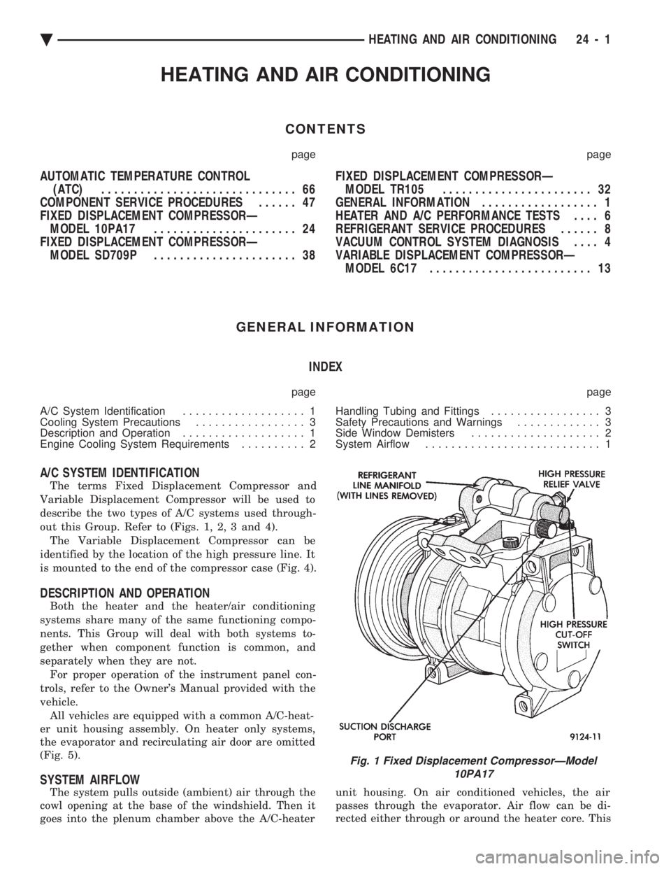
The terms Fixed Displacement Compressor and
Variable Displacement Compressor will be used to
describe the two types of A/C systems used through-
out this Group. Refer to (Figs. 1, 2, 3 and 4). The Variable Displacement Compressor can be
identified by the location of the high pressure line. It
is mounted to the end of the compressor case (Fig. 4).
DESCRIPTION AND OPERATION
Both the heater and the heater/air conditioning
systems share many of the same functioning compo-
nents. This Group will deal with both systems to-
gether when component function is common, and
separately when they are not. For proper operation of the instrument panel con-
trols, refer to the Owner's Manual provided with the
vehicle. All vehicles are equipped with a common A/C-heat-
er unit housing assembly. On heater only systems,
the evaporator and recirculating air door are omitted
(Fig. 5).
SYSTEM AIRFLOW
The system pulls outside (ambient) air through the
cowl opening at the base of the windshield. Then it
goes into the plenum chamber above the A/C-heater unit housing. On air conditioned vehicles, the air
passes through the evaporator. Air flow can be di-
rected either through or around the heater core. This
Fig. 1 Fixed Displacement CompressorÐModel 10PA17
Ä HEATING AND AIR CONDITIONING 24 - 1
Page 2306 of 2438
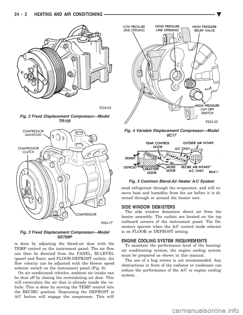
is done by adjusting the blend-air door with the
TEMP control on the instrument panel. The air flow
can then be directed from the PANEL, BI-LEVEL
(panel and floor), and FLOOR-DEFROST outlets. Air
flow velocity can be adjusted with the blower speed
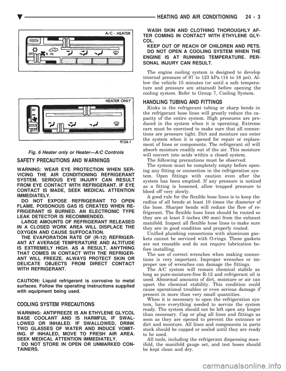
selector switch on the instrument panel (Fig. 6). On air conditioned vehicles, ambient air intake can
be shut off by closing the recirculating air door. This
will recirculate the air that is already inside the ve-
hicle. This is done by moving the TEMP control into
the RECIRC position. Depressing the DEFROST or
A/C button will engage the compressor. This will send refrigerant through the evaporator, and will re-
move heat and humidity from the air before it is di-
rected through or around the heater core.
SIDE WINDOW DEMISTERS
The side window demisters direct air from the
heater assembly. The outlets are located on the top
outboard corners of the instrument panel. The De-
misters operate when the A/C control mode selector
is on FLOOR or DEFROST setting.
ENGINE COOLING SYSTEM REQUIREMENTS
To maintain the performance level of the heating/
air conditioning system, the engine cooling system
must be prepared as shown in this manual. The use of a bug screen is not recommended. Any
obstructions in front of the radiator or condenser can
reduce the performance of the A/C or engine cooling
system.
Fig. 2 Fixed Displacement CompressorÐModel TR105
Fig. 3 Fixed Displacement CompressorÐModelSD709P
Fig. 4 Variable Displacement CompressorÐModel 6C17
Fig. 5 Common Blend-Air Heater A/C System
24 - 2 HEATING AND AIR CONDITIONING Ä
Page 2307 of 2438
SAFETY PRECAUTIONS AND WARNINGS
WARNING: WEAR EYE PROTECTION WHEN SER-
VICING THE AIR CONDITIONING REFRIGERANT
SYSTEM. SERIOUS EYE INJURY CAN RESULT
FROM EYE CONTACT WITH REFRIGERANT. IF EYE
CONTACT IS MADE, SEEK MEDICAL ATTENTION
IMMEDIATELY. DO NOT EXPOSE REFRIGERANT TO OPEN
FLAME. POISONOUS GAS IS CREATED WHEN RE-
FRIGERANT IS BURNED. AN ELECTRONIC TYPE
LEAK DETECTOR IS RECOMMENDED. LARGE AMOUNTS OF REFRIGERANT RELEASED
IN A CLOSED WORK AREA WILL DISPLACE THE
OXYGEN AND CAUSE SUFFOCATION. THE EVAPORATION RATE OF (R-12) REFRIGER-
ANT AT AVERAGE TEMPERATURE AND ALTITUDE
IS EXTREMELY HIGH. AS A RESULT, ANYTHING
THAT COMES IN CONTACT WITH THE REFRIGER-
ANT WILL FREEZE. ALWAYS PROTECT SKIN OR
DELICATE OBJECTS FROM DIRECT CONTACT
WITH REFRIGERANT.
CAUTION: Liquid refrigerant is corrosive to metal
surfaces. Follow the operating instructions supplied
with equipment being used.
COOLING SYSTEM PRECAUTIONS
WARNING: ANTIFREEZE IS AN ETHYLENE GLYCOL
BASE COOLANT AND IS HARMFUL IF SWAL-
LOWED OR INHALED. IF SWALLOWED, DRINK
TWO GLASSES OF WATER AND INDUCE VOMIT-
ING. IF INHALED, MOVE TO FRESH AIR AREA.
SEEK MEDICAL ATTENTION IMMEDIATELY. DO NOT STORE IN OPEN OR UNMARKED CON-
TAINERS. WASH SKIN AND CLOTHING THOROUGHLY AF-
TER COMING IN CONTACT WITH ETHYLENE GLY-
COL. KEEP OUT OF REACH OF CHILDREN AND PETS.
DO NOT OPEN A COOLING SYSTEM WHEN THE
ENGINE IS AT RUNNING TEMPERATURE. PER-
SONAL INJURY CAN RESULT.
The engine cooling system is designed to develop
internal pressure of 97 to 123 kPa (14 to 18 psi). Al-
low the vehicle 15 minutes (or until a safe tempera-
ture and pressure are attained) before opening the
cooling system. Refer to Group 7, Cooling System.
HANDLING TUBING AND FITTINGS
Kinks in the refrigerant tubing or sharp bends in
the refrigerant hose lines will greatly reduce the ca-
pacity of the entire system. High pressures are pro-
duced in the system when it is operating. Extreme
care must be exercised to make sure that all connec-
tions are pressure tight. Dirt and moisture can enter
the system when it is opened for repair or replace-
ment of lines or components. The refrigerant oil will
absorb moisture readily out of the air. This moisture
will convert into acids within a closed system. The following precautions must be observed:
The system must be completely empty before open-
ing any fitting or connection in the refrigeration sys-
tem. Open fittings with caution even after the
system has been emptied. If any pressure is noticed
as a fitting is loosened, allow trapped pressure to
bleed off very slowly. A good rule for the flexible hose lines is to keep the
radius of all bends at least 10 times the diameter of
the hose. Sharper bends will reduce the flow of re-
frigerant. The flexible hose lines should be routed so
they are at least 3 inches (80 mm) from the exhaust
manifold. Inspect all flexible hose lines to make sure
they are in good condition and properly routed. Unified plumbing connections with aluminum gas-
kets cannot be serviced with O-rings. These gaskets
are not reusable and do not require lubrication be-
fore installing. The use of correct wrenches when making connec-
tions is very important. Improper wrenches or im-
proper use of wrenches can damage the fittings. The A/C system will remain chemical stabile as
long as pure-moisture-free R-12 and refrigerant oil is
used. Abnormal amounts of dirt, moisture or air can
upset the chemical stability. This condition could
cause operational troubles or even serious damage if
present in more than very small quantities. When it is necessary to open the refrigeration sys-
tem, have everything needed to service the system
ready. The system should not be left open any longer
than necessary. Cap or plug all lines and fittings as
soon as they are opened to prevent the entrance or
dirt and moisture. All lines and components in parts
stock should be capped or sealed until they are ready
to be used. All tools, including the refrigerant dispensing man-
ifold, the manifold gauge set, and test hoses should
be kept clean and dry.
Fig. 6 Heater only or HeaterÐA/C Controls
Ä HEATING AND AIR CONDITIONING 24 - 3
Page 2312 of 2438
REFRIGERANT SERVICE PROCEDURES INDEX
page page
Adding Partial Refrigerant Charge ............ 10
Charging Refrigerant SystemÐEmpty System . . . 11
Discharging Refrigerant System .............. 11
Evacuating Refrigerant System .............. 11
Manifold Gauge Set Connections ............. 9 Oil Level
............................... 12
R-12 Refrigerant Equipment ................. 8
Refrigerant Recycling ...................... 9
Sight Glass Refrigerant Level Inspection ........ 8
Testing for Refrigerant Leaks ............... 10
SIGHT GLASS REFRIGERANT LEVEL INSPECTION
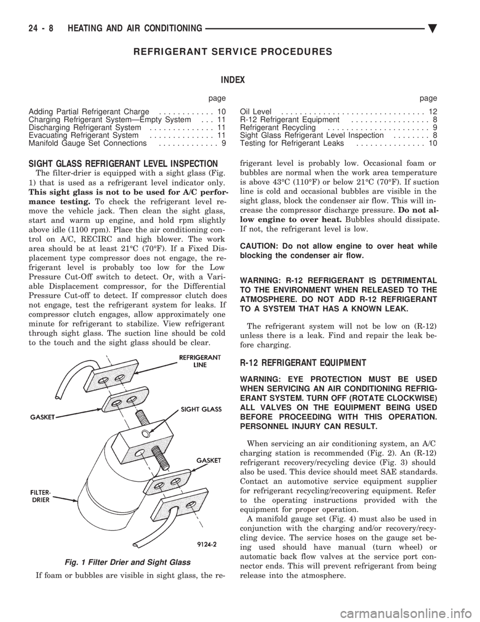
The filter-drier is equipped with a sight glass (Fig.
1) that is used as a refrigerant level indicator only.
This sight glass is not to be used for A/C perfor-
mance testing. To check the refrigerant level re-
move the vehicle jack. Then clean the sight glass,
start and warm up engine, and hold rpm slightly
above idle (1100 rpm). Place the air conditioning con-
trol on A/C, RECIRC and high blower. The work
area should be at least 21ÉC (70ÉF). If a Fixed Dis-
placement type compressor does not engage, the re-
frigerant level is probably too low for the Low
Pressure Cut-Off switch to detect. Or, with a Vari-
able Displacement compressor, for the Differential
Pressure Cut-off to detect. If compressor clutch does
not engage, test the refrigerant system for leaks. If
compressor clutch engages, allow approximately one
minute for refrigerant to stabilize. View refrigerant
through sight glass. The suction line should be cold
to the touch and the sight glass should be clear.
If foam or bubbles are visible in sight glass, the re- frigerant level is probably low. Occasional foam or
bubbles are normal when the work area temperature
is above 43ÉC (110ÉF) or below 21ÉC (70ÉF). If suction
line is cold and occasional bubbles are visible in the
sight glass, block the condenser air flow. This will in-
crease the compressor discharge pressure. Do not al-
low engine to over heat. Bubbles should dissipate.
If not, the refrigerant level is low.
CAUTION: Do not allow engine to over heat while
blocking the condenser air flow.
WARNING: R-12 REFRIGERANT IS DETRIMENTAL
TO THE ENVIRONMENT WHEN RELEASED TO THE
ATMOSPHERE. DO NOT ADD R-12 REFRIGERANT
TO A SYSTEM THAT HAS A KNOWN LEAK.
The refrigerant system will not be low on (R-12)
unless there is a leak. Find and repair the leak be-
fore charging.
R-12 REFRIGERANT EQUIPMENT
WARNING: EYE PROTECTION MUST BE USED
WHEN SERVICING AN AIR CONDITIONING REFRIG-
ERANT SYSTEM. TURN OFF (ROTATE CLOCKWISE)
ALL VALVES ON THE EQUIPMENT BEING USED
BEFORE PROCEEDING WITH THIS OPERATION.
PERSONNEL INJURY CAN RESULT.
When servicing an air conditioning system, an A/C
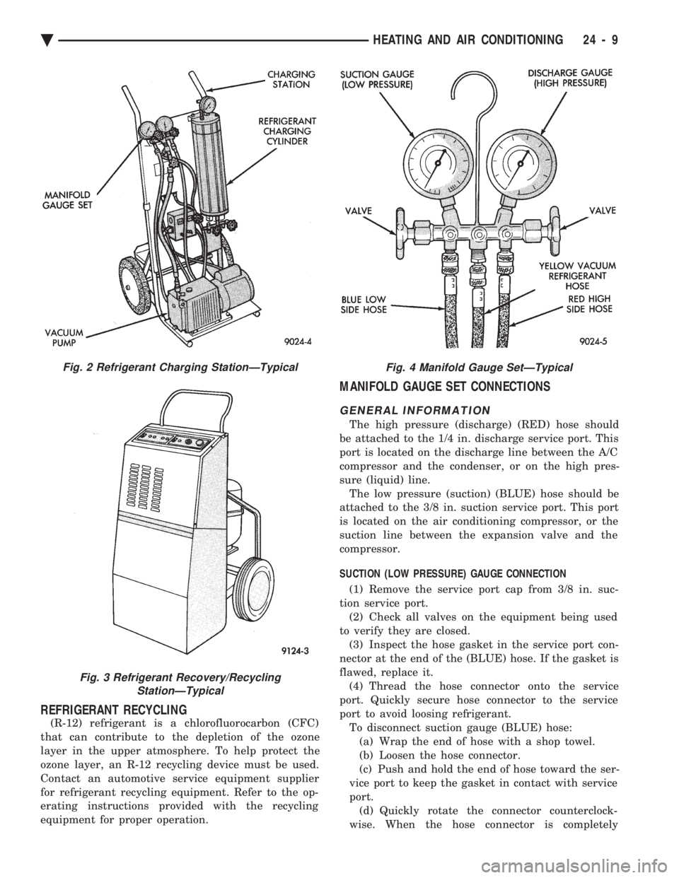
charging station is recommended (Fig. 2). An (R-12)
refrigerant recovery/recycling device (Fig. 3) should
also be used. This device should meet SAE standards.
Contact an automotive service equipment supplier
for refrigerant recycling/recovering equipment. Refer
to the operating instructions provided with the
equipment for proper operation. A manifold gauge set (Fig. 4) must also be used in
conjunction with the charging and/or recovery/recy-
cling device. The service hoses on the gauge set be-
ing used should have manual (turn wheel) or
automatic back flow valves at the service port con-
nector ends. This will prevent refrigerant from being
release into the atmosphere.
Fig. 1 Filter Drier and Sight Glass
24 - 8 HEATING AND AIR CONDITIONING Ä
Page 2313 of 2438
REFRIGERANT RECYCLING
(R-12) refrigerant is a chlorofluorocarbon (CFC)
that can contribute to the depletion of the ozone
layer in the upper atmosphere. To help protect the
ozone layer, an R-12 recycling device must be used.
Contact an automotive service equipment supplier
for refrigerant recycling equipment. Refer to the op-
erating instructions provided with the recycling
equipment for proper operation.
MANIFOLD GAUGE SET CONNECTIONS
GENERAL INFORMATION
The high pressure (discharge) (RED) hose should
be attached to the 1/4 in. discharge service port. This
port is located on the discharge line between the A/C
compressor and the condenser, or on the high pres-
sure (liquid) line. The low pressure (suction) (BLUE) hose should be
attached to the 3/8 in. suction service port. This port
is located on the air conditioning compressor, or the
suction line between the expansion valve and the
compressor.
SUCTION (LOW PRESSURE) GAUGE CONNECTION
(1) Remove the service port cap from 3/8 in. suc-
tion service port. (2) Check all valves on the equipment being used
to verify they are closed. (3) Inspect the hose gasket in the service port con-
nector at the end of the (BLUE) hose. If the gasket is
flawed, replace it. (4) Thread the hose connector onto the service
port. Quickly secure hose connector to the service
port to avoid loosing refrigerant. To disconnect suction gauge (BLUE) hose:(a) Wrap the end of hose with a shop towel.
(b) Loosen the hose connector.
(c) Push and hold the end of hose toward the ser-
vice port to keep the gasket in contact with service
port. (d) Quickly rotate the connector counterclock-
wise. When the hose connector is completely
Fig. 2 Refrigerant Charging StationÐTypical
Fig. 3 Refrigerant Recovery/Recycling StationÐTypical
Fig. 4 Manifold Gauge SetÐTypical
Ä HEATING AND AIR CONDITIONING 24 - 9