1993 CHEVROLET PLYMOUTH ACCLAIM temperature
[x] Cancel search: temperaturePage 458 of 2438

(3) Inspect the spark plug condition. Refer to Spark
Plug Condition in this section.
SPARK PLUG GAP ADJUSTMENT
Check the spark plug gap with a gap gauge. If the
gap is not correct, adjust it by bending the ground
electrode (Fig. 6).
SPARK PLUG INSTALLATION
(1) Start the spark plug into the cylinder head by
hand to avoid cross threading. (2) Tighten spark plugs to 28 N Im (20 ft. lbs.)
torque. (3) Install spark plug cables over spark plugs.
IDLE RPM TESTÐ2.5L AND 3.0L ENGINES
WARNING: APPLY PARKING BRAKE AND/OR BLOCK
WHEELS BEFORE PERFORMING IDLE CHECK OR
ADJUSTMENT, OR ANY TESTS WITH A RUNNING
ENGINE.
Engine idle set rpmshould be recorded when the
vehicle is first brought into shop for testing. This
will assist in diagnosing complaints of engine stalling,
creeping and hard shifting on vehicles equipped with
automatic transaxles. Proceed to the Throttle Body Minimum Airflow pro-
cedures in Group 14.
IGNITION TIMING PROCEDUREÐ2.2L TBI, 2.5L
TBI, 2.5L MPI, AND 3.0L ENGINES
WARNING: APPLY PARKING BRAKE AND/OR BLOCK
WHEELS BEFORE PERFORMING SETTING IGNITION
TIMING OR PERFORMING ANY TEST ON AN OPER-
ATING ENGINE.
Proper ignition timing is required to obtain optimum
engine performance. The distributor must be correctly
indexed to provide correct initial ignition timing. (1) Set the gearshift selector in park or neutral and
apply the parking brake. All lights and accessories
must be off. (2) If using a magnetic timing light, insert the
pickup probe into the open receptacle next to the
timing scale window. If a magnetic timing unit is not
available, use a conventional timing light connected to
the number one cylinder spark plug cable. Do not puncture cables, boots or nipples with
test probes. Always use proper adapters. Punc-
turing the spark plug cables with a probe will
damage the cables. The probe can separate the
conductor and cause high resistance. In addition
breaking the rubber insulation may permit sec-
ondary current to arc to ground. (3) Turn selector switch to the appropriate cylinder
position. (4) Start engine and run until operating tempera-
ture is obtained. (5) With the engine at normal operating tempera-
ture, connect the DRBII scan tool to the data link
connector (diagnostic connector). Access the State Dis-
play screen. Refer to the appropriate Powertrain Diag-
nostics Procedures Manual. If not using the DRBII
scan tool, disconnect the coolant temperature
sensor electrical connector. The electric radiator
fan will operate and the malfunction indicator lamp
(instrument panel Check Engine light) will turn on
after disconnecting the coolant sensor or starting the
DRBII scan tool procedure. (6) Aim Timing Light at timing scale (Fig. 7 or Fig.
8) or read magnetic timing unit. If flash occurs when
timing mark is before specified degree mark, timing is
advanced. To adjust, turn distributor housing in direc-
tion of rotor rotation. If flash occurs when timing mark is after specified
degree mark, timing is retarded. To adjust, turn dis-
tributor housing against direction of rotor rotation.
Refer to Vehicle Emission Control Information label for
correct timing specification. If timing is within 62É of
value specified on the label, proceed to step (8). If
outside specified tolerance, proceed to next step. (7) Loosen distributor hold-down arm screw
enough to rotate the distributor housing (Fig. 9 or
Fig. 6 Setting Spark Plug GapÐTypical
8D - 16 IGNITION SYSTEMS Ä
Page 459 of 2438

Fig. 10). Turn distributor housing to adjust timing.
Tighten the hold-down arm screw and recheck timing.
(8) Turn the engine off. Remove timing light or
magnetic timing unit and tachometer. If the coolant
temperature sensor was disconnected, connect the sen-
sor and erase fault codes using the Erase Fault
Code Mode on the DRBII scan tool.
DISTRIBUTORÐ2.2L TBI, 2.5L TBI AND 2.5L MPI
ENGINES
REMOVAL
(1) Disconnect distributor pick-up connector from
wiring harness connector (Fig. 11).
(2) Remove splash shield retaining screws (Fig.
12). (3) Remove splash shield (Fig. 12).
(4) Loosen distributor cap retaining screws (Fig.
13). (5) Lift cap off of distributor (Fig. 14).
(6) Rotate engine crankshaft until the distributor
rotor is pointing toward the cylinder block. Use this
as reference when reinstalling distributor. (7) Remove distributor hold-down screw.
(8) Carefully lift the distributor from the engine.
Fig. 10 Distributor HolddownÐ3.0L Engine
Fig. 11 Distributor Pickup ConnectorÐ2.5L Engine
Fig. 7 Timing ScaleÐ2.2L TBI, 2.5L TBI and 2.5L MPI Engines
Fig. 8 Timing ScaleÐ3.0L Engine
Fig. 9 Distributor HolddownÐ2.5L Engine
Ä IGNITION SYSTEMS 8D - 17
Page 466 of 2438

2.2L TURBO III, 3.3L AND 3.8L IGNITION SYSTEMÐSYSTEM OPERATION INDEX
page page
Auto Shutdown (ASD) Relay and Fuel Pump Relay ................................ 32
Camshaft Position Sensor .................. 28
Coolant Temperature Sensor ................ 32
Crankshaft Position Sensor ................. 29
General Information ....................... 24 Ignition Coil
............................. 31
Knock SensorÐTurbo III Engine ............. 32
Manifold Absolute Pressure (MAP) Sensor ..... 32
Powertrain Control Module (PCM) ............ 24
Spark Plug Cables ....................... 25
Spark Plugs ............................ 26
GENERAL INFORMATION
This section describes the ignition systems for 2.2L
Turbo III, 3.3L and 3.8L engines. The Fuel Injection sections of Group 14 describe On
Board Diagnostics. Group 0, Lubrication and Maintenance, contains
general maintenance information for ignition related
items. The Owner's Manual also contains maintenance
information. 2.2L Turbo III, 3.3L and 3.8L engines uses a
fixed ignition timing system. Basic ignition tim-
ing is not adjustable. All spark advance is deter-
mined by the powertrain control module (PCM). The ignition system does not use a distributor. The
system is referred to as the Direct Ignition System. The
system's three main components are the coil pack,
crankshaft position sensor, and camshaft position sen-
sor. The crankshaft and camshaft sensors are hall
effect devices. The camshaft position and crankshaft position sen-
sors generate pulses that are the inputs sent to the
PCM. The PCM interprets crankshaft and camshaft
position from these sensors. The PCM uses crankshaft
position sensor input to determine ignition timing. The
PCM determines injector sequence from the camshaft
position sensor. The camshaft position sensor determines when a
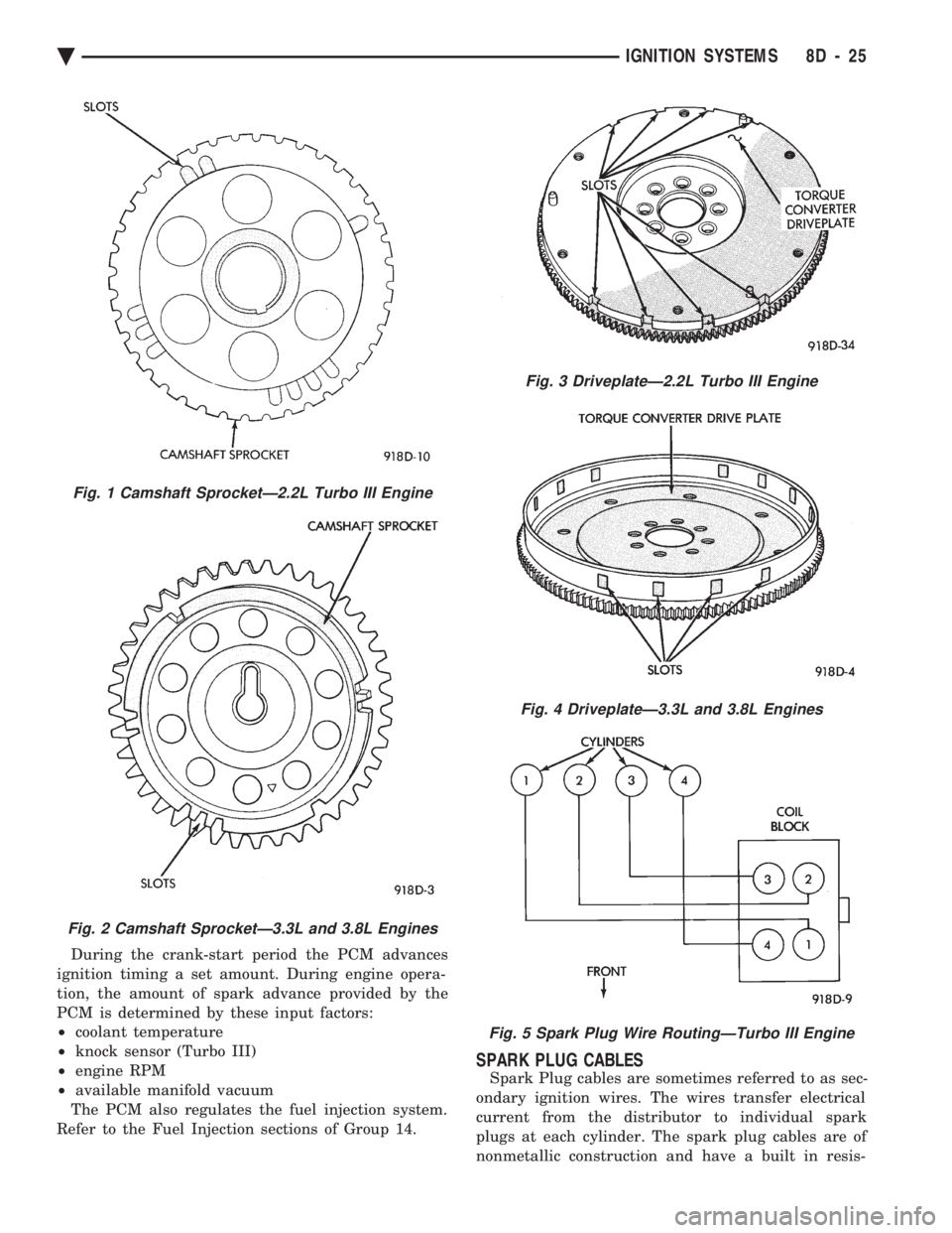
slot in the camshaft gear passes beneath it (Fig. 1 or
Fig. 2). The crankshaft position sensor determines
when a window in the drive plate passes under it
(Fig. 3 or Fig. 4). When metal aligns with the sensor,
voltage goes low (less than 0.5 volts). When a notch
aligns with the sensor, voltage spikes high (5.0
volts). As a group of notches pass under the sensor,
the voltage switches from low (metal) to high (notch)
then back to low.
FIRING ORDER
The firing order of the 2.2L Turbo III engine direct
ignition system is 1-3-4-2 (Fig. 5). The firing order of
the 3.3L and 3.8L engines direct ignition system is
1-2-3-4-5-6 (Fig. 6).
POWERTRAIN CONTROL MODULE (PCM)
The ignition system is regulated by the powertrain
control module (PCM) (Fig. 7). The PCM supplies
battery voltage to the ignition coil through the Auto
Shutdown (ASD) Relay. The PCM also controls
ground circuit for the ignition coil. By switching the
ground path for the coil on and off, the PCM adjusts
ignition timing to meet changing engine operating
conditions.
Fig. 37 Manifold Absolute Pressure (MAP) SensorÐ3.0L Engine
8D - 24 IGNITION SYSTEMS Ä
Page 467 of 2438

During the crank-start period the PCM advances
ignition timing a set amount. During engine opera-
tion, the amount of spark advance provided by the
PCM is determined by these input factors:
² coolant temperature
² knock sensor (Turbo III)
² engine RPM
² available manifold vacuum
The PCM also regulates the fuel injection system.
Refer to the Fuel Injection sections of Group 14.
SPARK PLUG CABLES
Spark Plug cables are sometimes referred to as sec-
ondary ignition wires. The wires transfer electrical
current from the distributor to individual spark
plugs at each cylinder. The spark plug cables are of
nonmetallic construction and have a built in resis-
Fig. 1 Camshaft SprocketÐ2.2L Turbo III Engine
Fig. 2 Camshaft SprocketÐ3.3L and 3.8L Engines
Fig. 3 DriveplateÐ2.2L Turbo III Engine
Fig. 4 DriveplateÐ3.3L and 3.8L Engines
Fig. 5 Spark Plug Wire RoutingÐTurbo III Engine
Ä IGNITION SYSTEMS 8D - 25
Page 469 of 2438

mal wear can usually be cleaned, have the electrodes
filed and regapped, and then reinstalled. Some fuel refiners in several areas of the United
States have introduced a manganese additive (MMT)
for unleaded fuel. During combustion, fuel with MMT
may coat the entire tip of the spark plug with a rust
colored deposit. The rust color deposits can be misdi-
agnosed as being caused by coolant in the combustion
chamber. Spark plug performance is not affected by
MMT deposits.
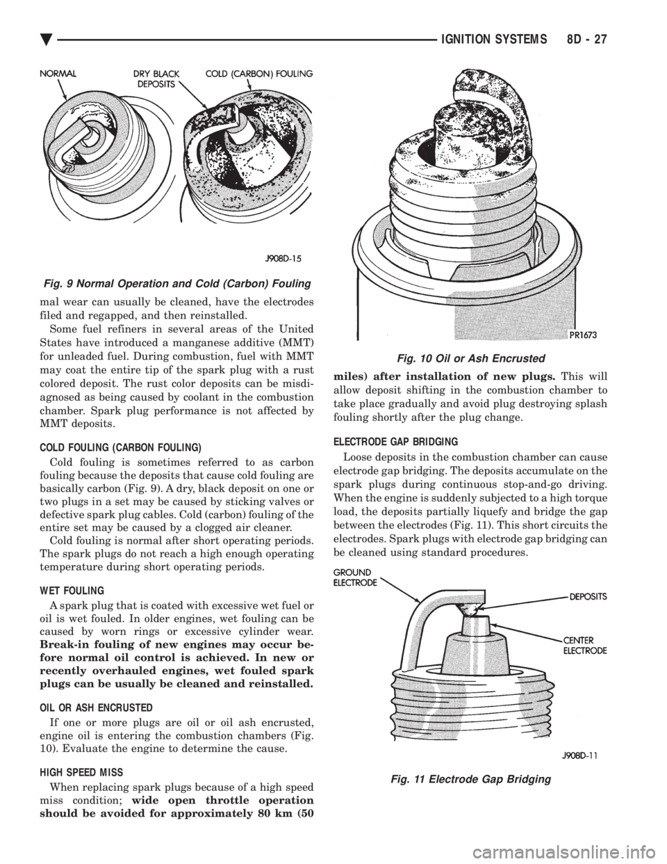
COLD FOULING (CARBON FOULING) Cold fouling is sometimes referred to as carbon
fouling because the deposits that cause cold fouling are
basically carbon (Fig. 9). A dry, black deposit on one or
two plugs in a set may be caused by sticking valves or
defective spark plug cables. Cold (carbon) fouling of the
entire set may be caused by a clogged air cleaner. Cold fouling is normal after short operating periods.
The spark plugs do not reach a high enough operating
temperature during short operating periods.
WET FOULING A spark plug that is coated with excessive wet fuel or
oil is wet fouled. In older engines, wet fouling can be
caused by worn rings or excessive cylinder wear.
Break-in fouling of new engines may occur be-
fore normal oil control is achieved. In new or
recently overhauled engines, wet fouled spark
plugs can be usually be cleaned and reinstalled.
OIL OR ASH ENCRUSTED If one or more plugs are oil or oil ash encrusted,
engine oil is entering the combustion chambers (Fig.
10). Evaluate the engine to determine the cause.
HIGH SPEED MISS When replacing spark plugs because of a high speed
miss condition; wide open throttle operation
should be avoided for approximately 80 km (50 miles) after installation of new plugs.
This will
allow deposit shifting in the combustion chamber to
take place gradually and avoid plug destroying splash
fouling shortly after the plug change.
ELECTRODE GAP BRIDGING
Loose deposits in the combustion chamber can cause
electrode gap bridging. The deposits accumulate on the
spark plugs during continuous stop-and-go driving.
When the engine is suddenly subjected to a high torque
load, the deposits partially liquefy and bridge the gap
between the electrodes (Fig. 11). This short circuits the
electrodes. Spark plugs with electrode gap bridging can
be cleaned using standard procedures.
Fig. 9 Normal Operation and Cold (Carbon) Fouling
Fig. 10 Oil or Ash Encrusted
Fig. 11 Electrode Gap Bridging
Ä IGNITION SYSTEMS 8D - 27
Page 470 of 2438

SCAVENGER DEPOSITS Fuel scavenger deposits may be either white or yel-
low (Fig. 12). They may appear to be harmful, but
are a normal condition caused by chemical additives
in certain fuels. These additives are designed to
change the chemical nature of deposits and decrease
spark plug misfire tendencies. Accumulation on the
ground electrode and shell area may be heavy but
the deposits are easily removed. Spark plugs with
scavenger deposits can be considered normal in con-
dition and be cleaned using standard procedures.
CHIPPED ELECTRODE INSULATOR A chipped electrode insulator usually results from
bending the center electrode while adjusting the
spark plug electrode gap. Under certain conditions,
severe detonation also can separate the insulator
from the center electrode (Fig. 13). Spark plugs with
chipped electrode insulators must be replaced.
PREIGNITION DAMAGE
Excessive combustion chamber temperature can
cause preignition damage. First, the center electrode
dissolves and the ground electrode dissolves some- what later (Fig. 14). Insulators appear relatively de-
posit free. Determine if the spark plug has the
correct heat range rating for the engine, if ignition
timing is over advanced or if other operating condi-
tions are causing engine overheating. The heat range
rating refers to the operating temperature of a par-
ticular type spark plug. Spark plugs are designed to
operate within specific temperature ranges depend-
ing upon the thickness and length of the center elec-
trode and porcelain insulator.
SPARK PLUG OVERHEATING
Overheating is indicated by a white or gray center
electrode insulator that also appears blistered (Fig.
15). The increase in electrode gap will be consider-
ably in excess of 0.001 in per 1000 miles of operation.
This suggests that a plug with a cooler heat range
rating should be used. Over advanced ignition tim-
ing, detonation and cooling system malfunctions also
can cause spark plug overheating.
CAMSHAFT POSITION SENSOR
The camshaft position sensor provides fuel injection
synchronization and cylinder identification informa-
Fig. 12 Scavenger Deposits
Fig. 13 Chipped Electrode Insulator
Fig. 14 Preignition Damage
Fig. 15 Spark Plug Overheating
8D - 28 IGNITION SYSTEMS Ä
Page 474 of 2438

The coil's low primary resistance allows the PCM to
fully charge the coil for each firing.
COOLANT TEMPERATURE SENSOR
On 2.2L Turbo III engines, the coolant temperature
sensor is installed into the thermostat housing (Fig. 30).
On 3.3L and 3.8L engines, the coolant temperature sensor
is located next to the thermostat housing (Fig. 31).
The coolant temperature sensor provides an input
voltage to the powertrain control module (PCM). The
sensor is a variable resistance (thermistor) with a
range of -40ÉC to 130ÉC (-40ÉF to 265ÉF). As coolant
temperature varies, the sensor resistance changes,
resulting in a different input voltage to the PCM.
The PCM contains different spark advance schedules
for cold and warm engine operation. The schedules reduce
engine emission and improve driveability.
The PCM demands slightly richer air-fuel mixtures
and higher idle speeds until the engine reaches normal
operating temperature. The coolant sensor input is also used for cooling
fan control.
KNOCK SENSORÐTURBO III ENGINE
Turbo III engines use a knock sensor. The sensor gen-
erates a signal when spark detonation occurs in the
combustion chambers. The sensor is mounted on the in-
take manifold behind the PCV breather (Fig. 32). The
sensor provides input voltage used by the powertrain
control module (PCM) to modify spark advance and
boost schedules in order to eliminate detonation.
MANIFOLD ABSOLUTE PRESSURE (MAP) SENSOR
The MAP sensor reacts to absolute pressure in the
intake manifold and provides an input voltage to the
powertrain control module (PCM). As engine load
changes, manifold pressure varies. The changes in
engine load cause the MAP output voltage to change.
The change in MAP sensor output voltage results in
a different input voltage to the PCM.
The input voltage level supplies the PCM with infor-
mation relating to ambient barometric pressure during
engine start-up (cranking) and engine load while its op-
erating. The PCM uses this input along with inputs
from other sensors to adjust air-fuel mixture.
On Turbo III engines, the MAP sensor is mounted
to the front right fender (Fig. 33) On 3.3L and 3.8L
engines, the MAP sensor (Fig. 34) is mounted to the
side of the intake manifold, below the positive crank-
case ventilation (PCV) valve. The sensor is connected
to the PCM electrically.
AUTO SHUTDOWN (ASD) RELAY AND FUEL PUMP
RELAY
The powertrain control module (PCM) operates the
auto shutdown (ASD) relay and fuel pump relay
through one ground path. The PCM operates the re-
lays by switching the ground path on and off. Both
relays turn on and off at the same time.
Fig. 32 Knock SensorÐTurbo III Engine
Fig. 30 Coolant Temperature SensorÐTurbo III En- gines
Fig. 31 Coolant Temperature SensorÐ3.3L and 3.8LEngines
8D - 32 IGNITION SYSTEMS Ä
Page 477 of 2438

2.2L TURBO III, 3.3L AND 3.8L IGNITION SYSTEMÐDIAGNOSTIC PROCEDURES INDEX
page page
Check Coil TestÐ3.3L and 3.8L Engines ...... 36
Check Coil TestÐTurbo III Engine ........... 35
Coolant Temperature Sensor Test ............ 38
Crankshaft Position Sensor and Camshaft Position Sensor Tests .......................... 38 Failure to Start Test
...................... 37
Failure to Start TestÐTurbo III Engine ........ 36
Manifold Absolute Pressure (MAP) Sensor Test . 38
Testing for Spark at CoilÐ3.3L and 3.8L Engines . 36
Testing for Spark at CoilÐTurbo III Engine ..... 35
TESTING FOR SPARK AT COILÐTURBO III ENGINE
WARNING: THE DIRECT IGNITION SYSTEM GENER-
ATES APPROXIMATELY 40,000 VOLTS. PERSONAL
INJURY COULD RESULT FROM CONTACT WITH
THIS SYSTEM.
The coil pack contains 2 independent coils. Each
coil must be checked individually.
CAUTION: Spark plug wire damage may occur if the
spark plug is moved more than 1/4 inch away from
the engine ground.
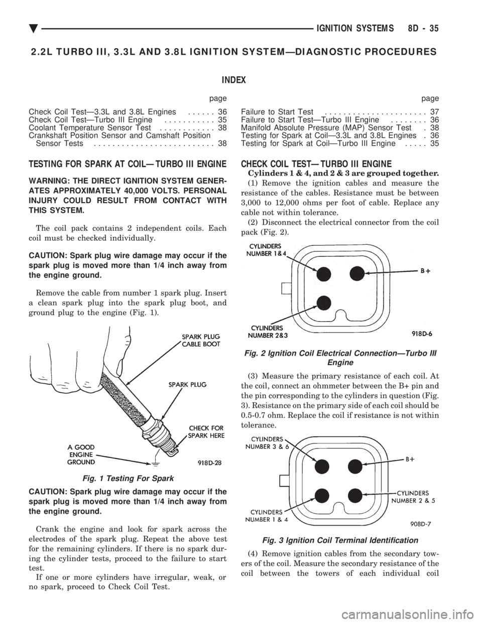
Remove the cable from number 1 spark plug. Insert
a clean spark plug into the spark plug boot, and
ground plug to the engine (Fig. 1).
CAUTION: Spark plug wire damage may occur if the
spark plug is moved more than 1/4 inch away from
the engine ground. Crank the engine and look for spark across the
electrodes of the spark plug. Repeat the above test
for the remaining cylinders. If there is no spark dur-
ing the cylinder tests, proceed to the failure to start
test. If one or more cylinders have irregular, weak, or
no spark, proceed to Check Coil Test.
CHECK COIL TESTÐTURBO III ENGINE
Cylinder s1&4,and2&3are grouped together.
(1) Remove the ignition cables and measure the
resistance of the cables. Resistance must be between
3,000 to 12,000 ohms per foot of cable. Replace any
cable not within tolerance. (2) Disconnect the electrical connector from the coil
pack (Fig. 2).
(3) Measure the primary resistance of each coil. At
the coil, connect an ohmmeter between the B+ pin and
the pin corresponding to the cylinders in question (Fig.
3). Resistance on the primary side of each coil should be
0.5-0.7 ohm. Replace the coil if resistance is not within
tolerance.
(4) Remove ignition cables from the secondary tow-
ers of the coil. Measure the secondary resistance of the
coil between the towers of each individual coil
Fig. 1 Testing For Spark
Fig. 2 Ignition Coil Electrical ConnectionÐTurbo III Engine
Fig. 3 Ignition Coil Terminal Identification
Ä IGNITION SYSTEMS 8D - 35