1993 CHEVROLET PLYMOUTH ACCLAIM ECO mode
[x] Cancel search: ECO modePage 743 of 2438
AUTOMATIC DAY/NIGHT INSIDE MIRROR
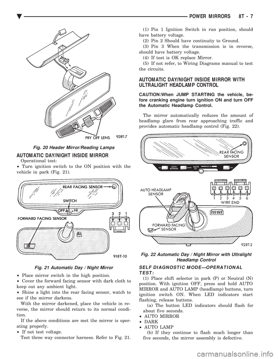
Operational test:
² Turn ignition switch to the ON position with the
vehicle in park (Fig. 21).
² Place mirror switch in the high position.
² Cover the forward facing sensor with dark cloth to
keep out any ambient light.
² Shine a light into the rear facing sensor, watch to
see if the mirror darkens. With the mirror darkened, place the vehicle in re-
verse, the mirror should return to its normal condi-
tion. If the above conditions are met the mirror is oper-
ating properly.
² If not test voltage.
Test three way connector harness. Refer to Fig. 21. (1) Pin 1 Ignition Switch in run position, should
have battery voltage. (2) Pin 2 Should have continuity to Ground.
(3) Pin 3 When the transmission is in reverse,
should have battery voltage. (4) If test is OK replace Mirror.
(5) If not refer, to Wiring Diagrams manual to test
the circuits.
AUTOMATIC DAY/NIGHT INSIDE MIRROR WITH
ULTRALIGHT HEADLAMP CONTROL
CAUTION:When JUMP STARTING the vehicle, be-
fore cranking engine turn ignition ON and turn OFF
the Automatic Headlamp Control.
The mirror automatically reduces the amount of
headlamp glare from rear approaching traffic and
provides automatic headlamp control (Fig. 22).
SELF DIAGNOSTIC MODEÐOPERATIONAL TEST:
(1) Place shift selector in park (P) or Neutral (N)
position. With ignition OFF, press and hold AUTO
MIRROR and AUTO LAMP (headlamp) buttons, turn
ignition switch ON. When LED indicators start
flashing, release buttons. (a) The button LED indicators should flash for
about five seconds.
² AUTO MIRROR
² DARK
² AUTO LAMP
(b) If they continue to flash much longer than
five seconds, the mirror assembly is defective.
Fig. 20 Header Mirror/Reading Lamps
Fig. 21 Automatic Day / Night Mirror
Fig. 22 Automatic Day / Night Mirror with Ultralight Headlamp Control
Ä POWER MIRRORS 8T - 7
Page 751 of 2438
GENERAL INFORMATION
CONTENTS
page page
CIRCUIT IDENTIFICATION ................. 3
COMPONENT IDENTIFICATION ............. 3
CONNECTORS ........................... 4
FUSIBLE LINKS ......................... 4
HARNESS REPAIR ....................... 4
LOCATING A SYSTEM .................... 3 SECONDARY IGNITION WIRING
............ 1
SPLICE LOCATIONS ...................... 3
SYMBOLS, FUSES AND RELAYS ........... 7
TROUBLESHOOTING WIRING PROBLEMS .... 4
WIRE CODE IDENTIFICATION .............. 2
WIRING DIAGRAM SHEETS AND INDEXES . . . 1
The wiring diagrams contain the latest information
at the time of publication. Throughout this group ref-
erences may be made to a particular vehicle by letter
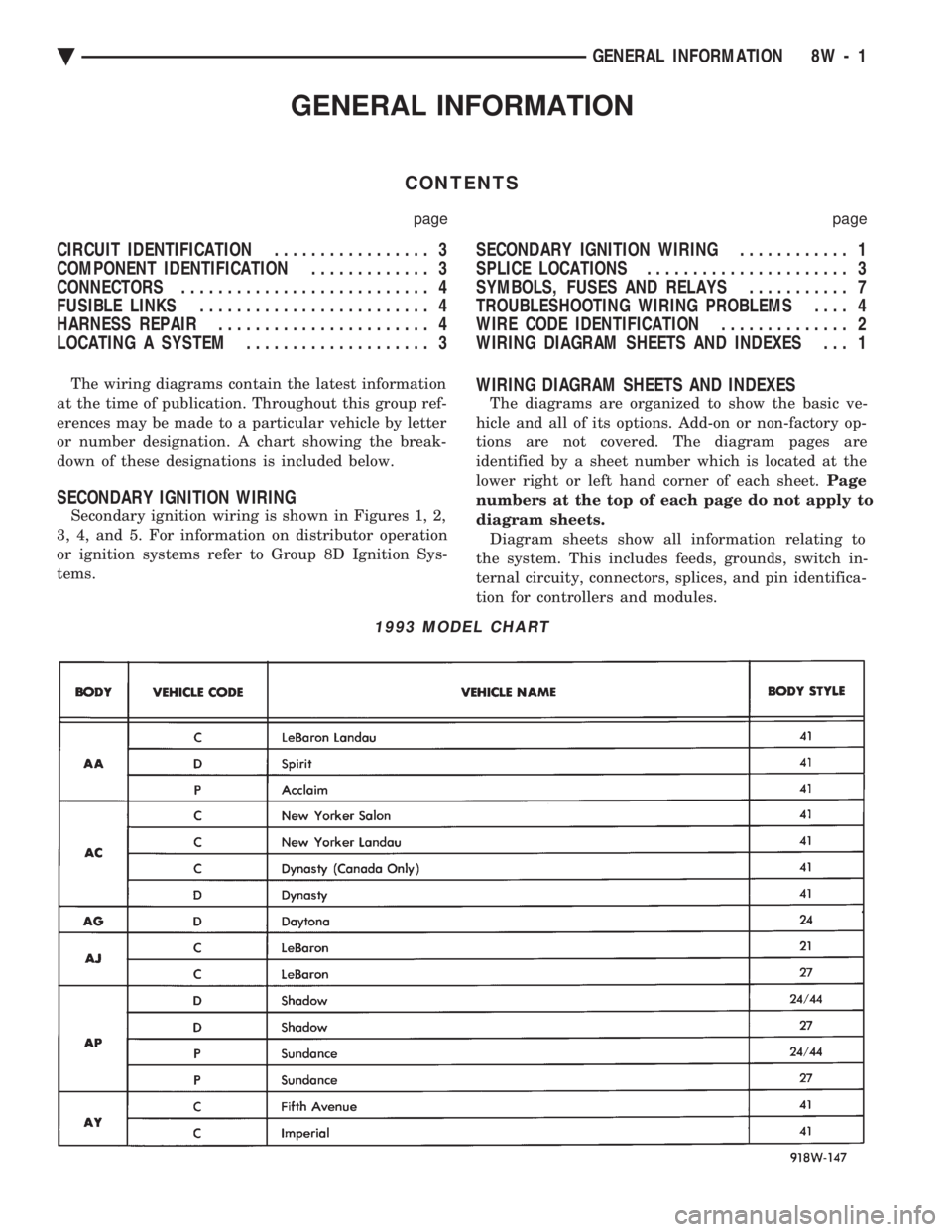
or number designation. A chart showing the break-
down of these designations is included below.
SECONDARY IGNITION WIRING
Secondary ignition wiring is shown in Figures 1, 2,
3, 4, and 5. For information on distributor operation
or ignition systems refer to Group 8D Ignition Sys-
tems.
WIRING DIAGRAM SHEETS AND INDEXES
The diagrams are organized to show the basic ve-
hicle and all of its options. Add-on or non-factory op-
tions are not covered. The diagram pages are
identified by a sheet number which is located at the
lower right or left hand corner of each sheet. Page
numbers at the top of each page do not apply to
diagram sheets. Diagram sheets show all information relating to
the system. This includes feeds, grounds, switch in-
ternal circuity, connectors, splices, and pin identifica-
tion for controllers and modules.
1993 MODEL CHART
Ä GENERAL INFORMATION 8W - 1
Page 753 of 2438

is non-standard the main wire color will have a slash
(/) after it followed by the tracer color.
CIRCUIT IDENTIFICATION
All circuits in the diagrams use an alpha/numeric
code to identify the wire and its function. To identify
which circuit code applies to a system, refer to the
Circuit Identification Code Chart. This chart shows
the main circuits only and does not show the second-
ary codes that may apply to some models.
LOCATING A SYSTEM
To locate a system or component in the diagrams,
refer to the alphabetical index at the front of the di-
agrams. Determine the diagram sheet number. Sheet
numbers are located at the lower right or left hand
corner of each sheet. Page numbers at the top of
the page do not apply to diagram sheets. The diagram index identifies the main system and
all components in that system. There are also sec-
tions of the index that identify specific components
only (for example modules, lamps, etc.). Refer to a
components name in the index if you are unclear as
to what a system may be called. Diagram pages are arranged starting with the bat-
tery and fuses. Then working into charging, starting,
and ignition systems. After this they start at the
front of the vehicle and work to rear of the vehicle.
The diagrams end with connector identification
pages.
COMPONENT IDENTIFICATION
When looking for a components location on the ve-
hicle refer to the wiring and components section.
This section shows the wire harness routing and the
components location in the vehicle. To use this sec-
tion refer to the wiring diagrams for the location of
the component. Then use the component identifica-
tion index to locate the proper figure number.
SPLICE LOCATIONS
Splices are indicated in the diagrams by a diamond
with a splice circuit code within it (Fig. 9 example 1).
If there is more than one splice per circuit a small
box will be connected to it with the splice number in
it (Fig. 9 example 2). To locate a splice in the wiring harness determine
the splice number from the wiring diagrams then re-
fer to the splice location index. This section shows
the general location of the splice in the harness.
Fig. 6 Wiring Diagram Page Sample
Fig. 7 Wire Color Code Identification
Fig. 8 Wire Color Code Chart
Ä GENERAL INFORMATION 8W - 3
Page 1617 of 2438
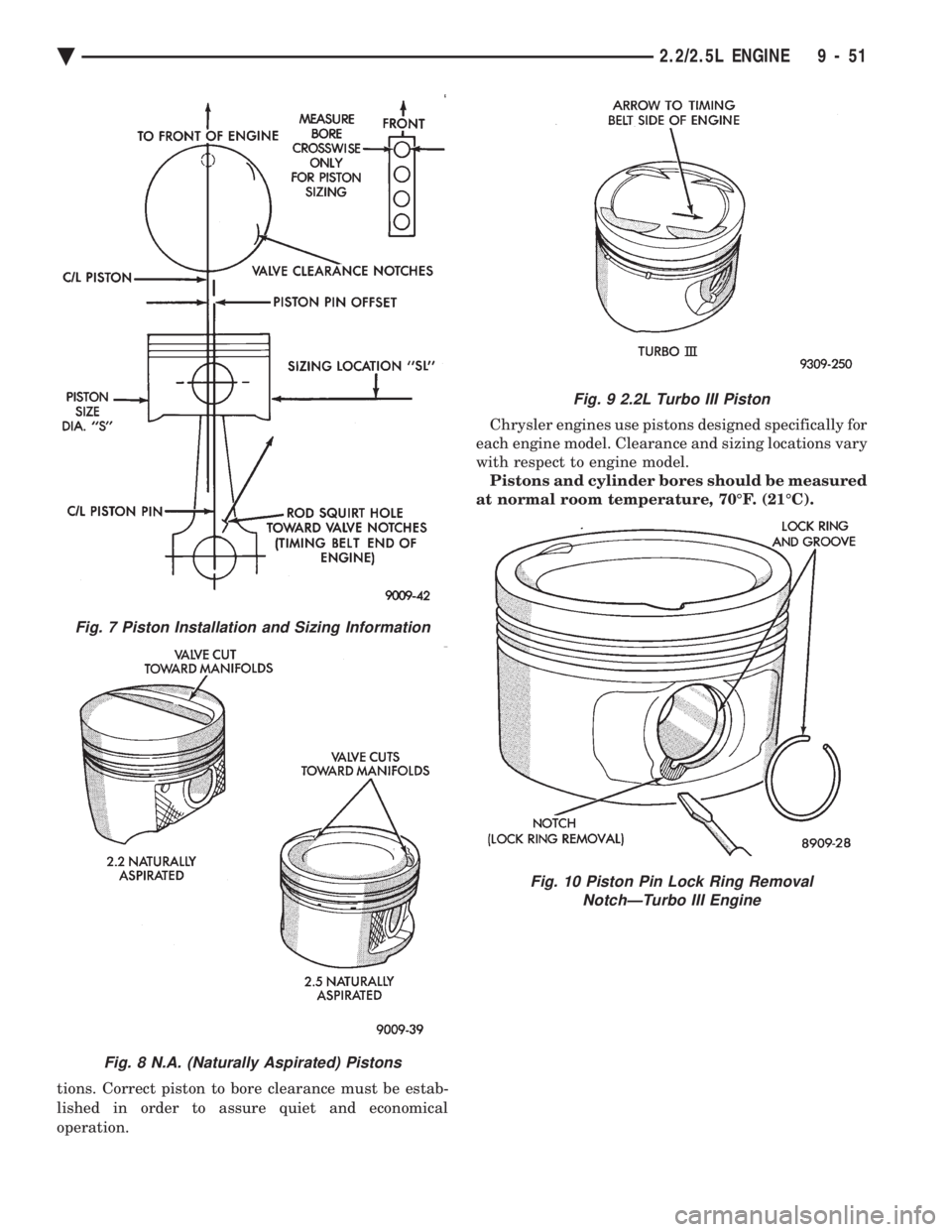
tions. Correct piston to bore clearance must be estab-
lished in order to assure quiet and economical
operation. Chrysler engines use pistons designed specifically for
each engine model. Clearance and sizing locations vary
with respect to engine model. Pistons and cylinder bores should be measured
at normal room temperature, 70ÉF. (21ÉC).
Fig. 7 Piston Installation and Sizing Information
Fig. 8 N.A. (Naturally Aspirated) Pistons
Fig. 9 2.2L Turbo III Piston
Fig. 10 Piston Pin Lock Ring Removal NotchÐTurbo III Engine
Ä 2.2/2.5L ENGINE 9 - 51
Page 1770 of 2438
The PCM removes the ground to the solenoid when
the engine reaches a specified temperature and the
time delay interval has occurred. When the solenoid is
de-energized, vacuum flows to the canister purge
valve. Vapors are purged from the canister and flow to
the throttle body. The purge solenoid is also energized during certain
idle conditions to update the fuel delivery calibration.
MALFUNCTION INDICATOR LAMP (CHECK
ENGINE)ÐPCM OUTPUT
The Malfunction Indicator lamp (instrument panel
Check Engine lamp) comes on each time the ignition
key is turned ON and stays on for 3 seconds as a bulb
test. The malfunction indicator lamp warns the opera-
tor that the PCM has entered a Limp-in mode. During
Limp-in-Mode, the PCM attempts to keep the system
operational. The malfunction indicator lamp signals
the need for immediate service. In limp-in mode, the
PCM compensates for the failure of certain components
that send incorrect signals. The PCM substitutes for
the incorrect signals with inputs from other sensors. Signals that can trigger the Malfunction Indi-
cator Lamp.
² Coolant Temperature Sensor
² Manifold Absolute Pressure Sensor
² Throttle Position Sensor
² Battery Voltage Input
² An Emissions Related System
² Charging system
The malfunction indicator lamp can also be used to
display diagnostic trouble codes. Cycle the ignition
switch on, off, on, off, on, within five seconds and any
diagnostic trouble codes stored in the PCM will be
displayed. Refer to the 2.2L/2.5L Single Point Fuel
InjectionÐOn-Board Diagnostics section in this group.
DATA LINK CONNECTORÐPCM OUTPUT
The data link connector provides the technician with
the means to connect the DRBII scan tool to diagnosis
the vehicle.
ELECTRIC ELECTRONIC GAS
RECIRCULATIONÐPCM OUTPUT
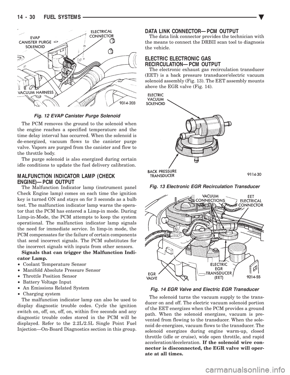
The electronic exhaust gas recirculation transducer
(EET) is a back pressure transducer/electric vacuum
solenoid assembly (Fig. 13). The EET assembly mounts
above the EGR valve (Fig. 14).
The solenoid turns the vacuum supply to the trans-
ducer on and off. The electric vacuum solenoid portion
of the EET energizes when the PCM provides a ground
path. When the solenoid energizes, vacuum is pre-
vented from flowing to the transducer. When the sole-
noid de-energizes, vacuum flows to the transducer. The
solenoid energizes during engine warm-up, closed
throttle (idle or cruise), wide open throttle, and rapid
acceleration/deceleration. If the solenoid wire con-
nector is disconnected, the EGR valve will oper-
ate at all times.
Fig. 12 EVAP Canister Purge Solenoid
Fig. 13 Electronic EGR Recirculation Transducer
Fig. 14 EGR Valve and Electric EGR Transducer
14 - 30 FUEL SYSTEMS Ä
Page 1771 of 2438
FUEL INJECTORÐPCM OUTPUT
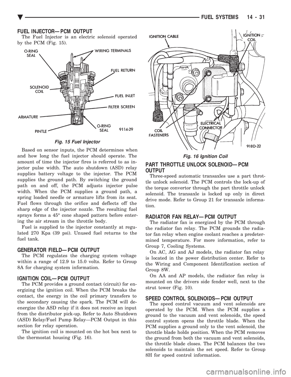
The Fuel Injector is an electric solenoid operated
by the PCM (Fig. 15).
Based on sensor inputs, the PCM determines when
and how long the fuel injector should operate. The
amount of time the injector fires is referred to as in-
jector pulse width. The auto shutdown (ASD) relay
supplies battery voltage to the injector. The PCM
supplies the ground path. By switching the ground
path on and off, the PCM adjusts injector pulse
width. When the PCM supplies a ground path, a
spring loaded needle or armature lifts from its seat.
Fuel flows through the orifice and deflects off the
sharp edge of the injector nozzle. The resulting fuel
sprays forms a 45É cone shaped pattern before enter-
ing the air stream in the throttle body. Fuel is supplied to the injector constantly at regu-
lated 270 Kpa (39 psi). Unused fuel returns to the
fuel tank.
GENERATOR FIELDÐPCM OUTPUT
The PCM regulates the charging system voltage
within a range of 12.9 to 15.0 volts. Refer to Group
8A for charging system information.
IGNITION COILÐPCM OUTPUT
The PCM provides a ground contact (circuit) for en-
ergizing the ignition coil. When the PCM breaks the
contact, the energy in the coil primary transfers to
the secondary causing the spark. The PCM will de-
energize the ASD relay if it does not receive an input
from the distributor pick-up. Refer to Auto Shutdown
(ASD) Relay/Fuel Pump RelayÐPCM Output in this
section for relay operation. The ignition coil is mounted on the hot box next to
the thermostat housing (Fig. 16).
PART THROTTLE UNLOCK SOLENOIDÐPCM
OUTPUT
Three-speed automatic transaxles use a part throt-
tle unlock solenoid. The PCM controls the lock-up of
the torque convertor through the part throttle unlock
solenoid. The transaxle is locked up only in direct
drive mode. Refer to Group 21 for transaxle informa-
tion.
RADIATOR FAN RELAYÐPCM OUTPUT
The radiator fan is energized by the PCM through
the radiator fan relay. The PCM grounds the radia-
tor fan relay when engine coolant reaches a predeter-
mined temperature. For more information, refer to
Group 7, Cooling Systems. On AC, AG and AJ models, the radiator fan relay
is located in the power distribution center. Refer to
the Wiring and Component Identification section of
Group 8W. On AA and AP models, the radiator fan relay is
mounted on the drivers side fender well, next to the
strut tower (Fig. 10).
SPEED CONTROL SOLENOIDSÐPCM OUTPUT
The speed control vacuum and vent solenoids are
operated by the PCM. When the PCM supplies a
ground to the vacuum and vent solenoids, the speed
control system opens the throttle blade. When the
PCM supplies a ground only to the vent solenoid, the
throttle blade holds position. When the PCM removes
the ground from both the vacuum and vent solenoids,
the throttle blade closes. The PCM balances the two
solenoids to maintain the set speed. Refer to Group
8H for speed control information.
Fig. 15 Fuel Injector
Fig. 16 Ignition Coil
Ä FUEL SYSTEMS 14 - 31
Page 1772 of 2438
TACHOMETERÐPCM OUTPUT
The PCM supplies engine RPM to the instrument
panel tachometer. Refer to Group 8 for tachometer
information.
MODES OF OPERATION
As input signals to the PCM change, the PCM
adjusts its response to the output devices. For example,
the PCM must calculate a different injector pulse
width and ignition timing for idle than it does for wide
open throttle (WOT). There are several different modes
of operation that determine how the PCM responds to
the various input signals. There are two different areas of operation, OPEN
LOOP and CLOSED LOOP. During OPEN LOOP modes, the PCM receives input
signals and responds according to preset PCM pro-
gramming. Input from the oxygen (O
2) sensor is not
monitored during OPEN LOOP modes. During CLOSED LOOP modes, the PCM does moni-
tor the oxygen (O
2) sensor input. This input tells the
PCM if the calculated injector pulse width results in an
air-fuel ratio of 14.7 to 1. By monitoring the exhaust
oxygen content, the can PCM fine tune injector pulse
width for optimum fuel economy and low emissions. The single point fuel injection system has the follow-
ing modes of operation:
² Ignition switch ON - Zero RPM
² Engine start-up
² Engine warm-up
² Cruise (Idle)
² Acceleration
² Deceleration
² Wide Open Throttle
² Ignition switch OFF
The engine start-up (cranking), engine warm-up, and
wide open throttle modes are OPEN LOOP modes. The
acceleration, deceleration, and cruise modes, with the
engine at operating temperature are CLOSED
LOOP modes (under most operating conditions).
IGNITION SWITCH ON (ZERO RPM) MODE
When the single point fuel injection system is acti-
vated by the ignition switch, the following actions
occur:
² The PCM determines atmospheric air pressure from
the MAP sensor input to calculate basic fuel strategy.
² The PCM monitors the coolant temperature sensor
and throttle position sensor inputs. The PCM modifies
fuel strategy based on these inputs. When the key is in the ON position and the engine is
not running, the (ASD) and fuel pump relays are not
energized. Therefore, battery voltage is not supplied to
the fuel pump, ignition coil, fuel injector or oxygen
sensor heating element. ENGINE START-UP MODE
This is an OPEN LOOP mode. The following actions
occur when the starter motor is engaged. If the PCM receives a distributor signal it energizes
the auto shutdown (ASD) relay and fuel pump relay to
supply battery voltage to the fuel injector, ignition coil
and oxygen sensor heating element. If the PCM does
not receive a distributor input, it de-energizes the ASD
and fuel pump relays after approximately one second. When the engine idles within 664 RPM of the target
RPM, the PCM compares the current MAP value with
the atmospheric pressure value it received during the
Ignition Switch On (Zero RPM) Mode. If a minimum
difference between the two is not detected, a MAP
sensor fault is set into memory. Once the ASD relay and fuel pump relay have ener-
gized, the PCM:
² Supplies a ground path to the injector. The injector
is pulsed four times per engine revolution instead of
the normal two pulses per revolution.
² Determines injector pulse width based on coolant
temperature, MAP sensor input, throttle position, and
the number of engine revolutions since cranking was
initiated.
² Monitors the coolant temperature sensor, distribu-
tor pick-up, MAP sensor, and throttle position sensor to
determine correct ignition timing.
ENGINE WARM-UP MODE
This is a OPEN LOOP mode. The following inputs
are received by the PCM:
² coolant temperature
² manifold absolute pressure (MAP)
² engine speed (distributor pick-up)
² throttle position
² A/C switch
² battery voltage
The PCM provides a ground path for the injector to
precisely control injector pulse width (by switching the
ground on and off) and fires the injector twice per
engine revolution. The PCM regulates ignition timing.
It also adjusts engine idle speed through the idle air
control motor.
CRUISE OR IDLE MODE
When the engine is at operating temperature this is
a CLOSED LOOP mode. During cruising speed and at
idle the following inputs are received by the PCM:
² coolant temperature
² manifold absolute pressure
² engine speed
² throttle position
² exhaust gas oxygen content
² A/C control positions
² battery voltage
14 - 32 FUEL SYSTEMS Ä
Page 1773 of 2438
The PCM provides a ground path for the injector to
precisely control injector pulse width and fires the in-
jector twice per engine revolution. The PCM controls
engine idle speed and ignition timing. The PCM con-
trols the air/fuel ratio according to the oxygen con-
tent in the exhaust gas.
ACCELERATION MODE This is a CLOSED LOOP mode. The PCM recog-
nizes an abrupt increase in throttle position or MAP
pressure as a demand for increased engine output
and vehicle acceleration. The PCM increases injector
pulse width in response to increased fuel demand.
DECELERATION MODE This is a CLOSED LOOP mode. During decelera-
tion the following inputs are received by the PCM:
² coolant temperature
² manifold absolute pressure
² engine speed
² throttle position
² exhaust gas oxygen content
² A/C control positions
² battery voltage
The PCM may receive a closed throttle input from
the throttle position sensor (TPS) at the same time it
senses an abrupt decrease in manifold pressure from
the manifold absolute pressure (MAP) sensor. This
indicates a hard deceleration. The PCM may reduce
injector firing to once per engine revolution. This
helps maintain better control of the air-fuel mixture
(as sensed through the O
2sensor).
During a deceleration condition, the PCM grounds
the exhaust gas recirculation transducer (EET) sole-
noid. EGR stops when the PCM grounds the solenoid.
WIDE OPEN THROTTLE MODE This is an OPEN LOOP mode. During wide open
throttle operation, the following inputs are received
by the PCM:
² coolant temperature
² manifold absolute pressure
² engine speed
² throttle position
When the PCM senses a wide open throttle condi-
tion through the throttle position sensor (TPS) it
will:
² De-energize the air conditioning relay. This dis-
ables the air conditioning system.
² Provide a ground path for the electric EGR trans-
ducer (EET) solenoid, preventing the EGR system
from functioning. The exhaust gas oxygen content input is not ac-
cepted by the PCM during wide open throttle opera- tion. The PCM will adjust injector pulse width to
supply a predetermined amount of additional fuel.
IGNITION SWITCH OFF MODE
When the ignition switch is turned to the OFF po-
sition, the following occurs:
² All outputs are turned off.
² No inputs are monitored.
² The PCM shuts down.
FUEL PRESSURE REGULATOR
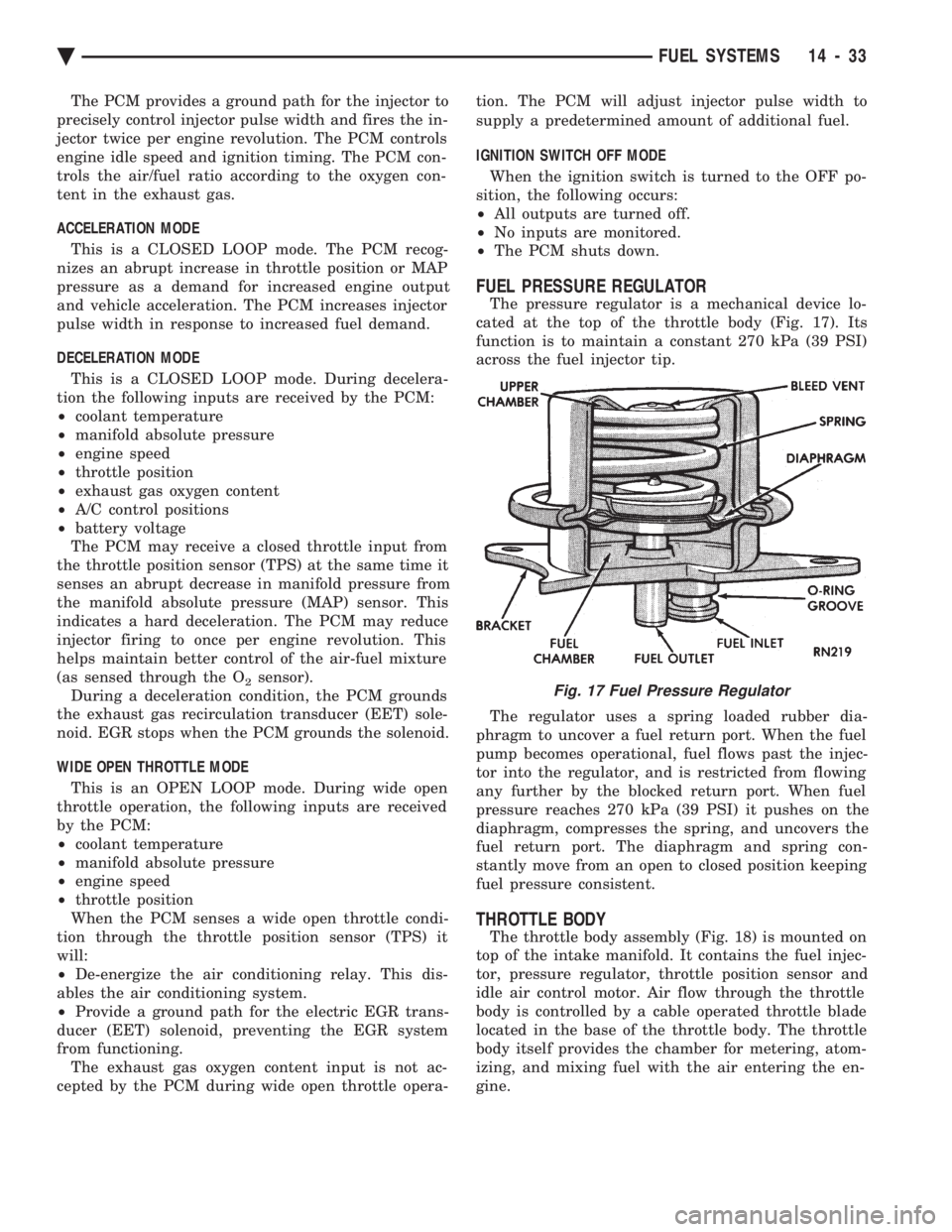
The pressure regulator is a mechanical device lo-
cated at the top of the throttle body (Fig. 17). Its
function is to maintain a constant 270 kPa (39 PSI)
across the fuel injector tip.
The regulator uses a spring loaded rubber dia-
phragm to uncover a fuel return port. When the fuel
pump becomes operational, fuel flows past the injec-
tor into the regulator, and is restricted from flowing
any further by the blocked return port. When fuel
pressure reaches 270 kPa (39 PSI) it pushes on the
diaphragm, compresses the spring, and uncovers the
fuel return port. The diaphragm and spring con-
stantly move from an open to closed position keeping
fuel pressure consistent.
THROTTLE BODY
The throttle body assembly (Fig. 18) is mounted on
top of the intake manifold. It contains the fuel injec-
tor, pressure regulator, throttle position sensor and
idle air control motor. Air flow through the throttle
body is controlled by a cable operated throttle blade
located in the base of the throttle body. The throttle
body itself provides the chamber for metering, atom-
izing, and mixing fuel with the air entering the en-
gine.
Fig. 17 Fuel Pressure Regulator
Ä FUEL SYSTEMS 14 - 33