1993 CHEVROLET PLYMOUTH ACCLAIM heater
[x] Cancel search: heaterPage 1471 of 2438
Wiring Diagram
Name Sheet Number
Splice M1-3 ........................... .40, 55
Splice M2-1 ...............................39
Splice P33 ............................ .62, 64
Splice P34 ............................ .62, 64
Splice Q1 ................................58
Splice T13 ...............................24
Splice T16 ...............................25
Splice T41 ...............................23
Splice T41-1 ............................9,10
Splice X2 ................................42
Splice X2-1 ...............................42
Splice X13 ...............................66
Splice X15 ...............................66
Splice Z0 .................................3
Splice Z0-1 ...............................14
Splice Z0-2 ...............................21
Splice Z1 ......... .40, 44, 55, 57, 60, 61, 63, 68, 69, 71
Splice Z1-1 ...................... .38, 46, 47, 66
Splice Z1-2 ......................... .31, 33, 42
Splice Z1-3 ......................... .32, 34, 42
Splice Z1-4 ............7,27,28,29,32,34,42,45,49
Splice Z1-5 .................... .55, 57, 60, 61, 63
Splice Z1-6 ...............................38
Splice Z1-7 ........................... .70, 72
Splice Z1-8 ........................... .67, 70
Splice Z1-10 ........................... .32, 34
Splice Z1-11 ........................ .32, 34, 42
Splice Z1-12 .............. .55, 57, 60, 61, 63, 69, 71
Splice Z1-14 ........................... .27, 28
Splice Z2 ................................38
Splice Z12 ............................ .14, 21
Splice Z13 ...............................25
Splice Z14 ...............................25
Steering Column Connectors ......................81
Steering Multi-Function Switch Column Connectors .......82
Stereo Radio ................................65
Stop Lamp System ............................29
Stop Lamp Switch ............................29
Switches A/C Cycling Clutch Switch ......................48
A/C Switch ...............................47
A/C Heater Blower Switch ......................47
A/C High Pressure Switch ......................48
A/C Low Pressure Switch ......................48
Back-Up Lamp Switch .....................7,8,9
Blower Switch-A/C Heater ......................47
Brake Warning Lamp Switch ....................11
Clutch Pedal Position Switch ...................7,9
Defrost Switch .............................47
Door Lock Switch (2-dr) ................... .61, 62
Door Lock Switch (4-dr) ................... .63, 64
Door Jamb Switch ....................... .39, 40
Dual Mirror Control Switch .....................55
Engine Oil Pressure Switch .....................12
Fog Lamp Switch ........................ .31, 33
Glove Box Lamp Switch .......................39
Hazard Flasher Switch ........................52Wiring Diagram
Name Sheet Number
Headlamp Switch .........................1,36
Heated Rear Window Switch ....................67
Heater Bi-level Control Switch ...................46
Horn Switch ..............................42
Ignition Switch ...........................2,11
Liftgate Latch Switch .........................40
Mercury Switch ............................12
Park Brake Switch ...........................11
Park/Neutral Position Switch .....................8
Park/Neutral Start Switch ......................23
Power Mirrors Switch ........................55
Power Seat Switch ..........................60
Power Steering Pressure Switch ..................19
Power Window Switch (2 Dr) ...................57
Power Window Switch (4 Dr) ...................58
Seat Belt Warning Switch ......................44
Speed Control Switch ........................29
Stop Lamp Switch ..........................29
Transmission Range Switch .....................25
Transmission Solenoids and Pressure Switch ..........25
Turn Signal Flasher Switch .....................52
Vehicle Speed Control Switch ...................29
Wiper Park Switch ..........................54
Wiper Switch ..............................53
Temperature Sending Unit .......................18
Time Delay Relay .............................44
Throttle Position (Sensor) 2.2L ....................16
Throttle Position (Sensor) 2.5L ....................16
THrottle Position (Sensor) 3.0L ....................20
Transmission Control Module Connector ..............91
Transmission Control System ................23, 24, 25
Back-up Lamp Relay .........................23
Output Speed Sensor .........................24
Park/Neutral Switch ..........................23
Safety Shut Down Relay .......................25
Transmission Control Module ...............23, 24, 25
Transmission Range Switch .....................25
Transmission Solenoids and Pressure Switch ..........25
Turbine Speed Sensor ........................24
Transmission EMCC Solenoid ......................8
Transmission Solenoid Connector ..................92
Transmission Solenoids and Pressure Switch ...........25
Turn and Hazard Flasher System .................51, 52
Hazard Flasher ......................... .51, 52
Switch ..................................52
Turn Signal Flasher ..........................51
Turn Signal Lamps ..........31, 32, 33, 34, 69, 70, 71, 72
Underhood Lamp .............................12
Vehicle Speed Control Servo ......................29
Vehicle Speed Control and Stop Lamp System ..........29
Clockspring ................................29
Powertrain Control Module .......................29
Stop Lamp Switch with Vehicle Speed Control ..........29
Stop Lamp without Vehicle Speed Control .............29
Vehicle Speed Control Servo ......................29
Vehicle Speed Control Switch .....................29
Wiper System ........................... .53, 54
Ä WIRING DIAGRAMS AP BODY D-P 8W - 721
Page 1579 of 2438
² Drive shaft distress: See Driveshafts in Suspension,
Group 2.
² Any front end structural damage (after repair).
² Insulator replacement.
ENGINE MOUNT INSULATOR ADJUSTMENT
(1) Remove the load on the engine motor mounts by
carefully supporting the engine and transmission as-
sembly with a floor jack. (2) Loosen the right engine mount insulator vertical
fasteners, and the front engine mount bracket to front
crossmember screws and nuts. Left engine mount insulator is sleeved over
shaft and long support bolt to provide lateral
movement adjustment with engine weight re-
moved or not. (3) Pry the engine right or left as required to achieve
the proper drive shaft assembly length. See Drive
Shaft in Suspension Group 2 for driveshaft identifica-
tion and related assembly length measuring. (4) Tighten right engine mount insulator vertical
bolts to 68 N Im (50 ft. lbs.). Then tighten front engine
mount screws and nuts to 54 N Im (40 ft. lbs.) and
center left engine mount insulator. (5) Recheck drive shaft length.
ENGINE ASSEMBLY
REMOVAL
(1) Disconnect battery.
(2) Scribe hood hinge outline on hood and remove
hood. (3) Drain cooling system.
(4) Remove hoses from radiator and engine.
(5) Remove radiator and fan assembly.
(6) Remove air cleaner and hoses.
(7) Remove air conditioning compressor mounting
bolts and set compressor aside, if equipped. (8) Remove power steering pump mounting bolts
and set pump aside (9) Remove oil filter.
(10) Disconnect fuel line, heater hose and acceler-
ator cable. (11) Disconnect all electrical connections and har-
nesses at throttle body and engine. (12) Manual Transmission
(a) Disconnect clutch cable.
(b) Remove transmission case lower cover.
(c) Disconnect exhaust pipe at manifold.
(d) Disconnect starter and lay aside.
(e) Install transmission holding fixture.
(13) Automatic Transmission
(a) Disconnect exhaust pipe at manifold.
(b) Disconnect starter and lay aside.
(c) Remove transmission case lower cover.
(d) Mark flex plate to torque converter.
(e) Remove screws holding torque converter to
flex plate.
(14) Attach C clamp on front bottom of torque con-
verter housing to prevent torque converter from com-
ing out. (15) Install transmission holding fixture.
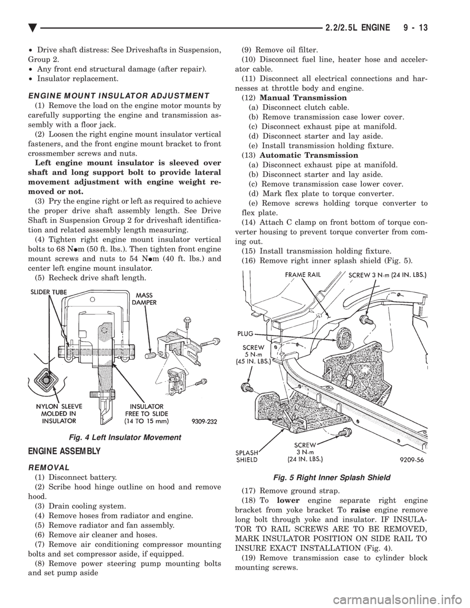
(16) Remove right inner splash shield (Fig. 5).
(17) Remove ground strap.
(18) To lowerengine separate right engine
bracket from yoke bracket To raiseengine remove
long bolt through yoke and insulator. IF INSULA-
TOR TO RAIL SCREWS ARE TO BE REMOVED,
MARK INSULATOR POSITION ON SIDE RAIL TO
INSURE EXACT INSTALLATION (Fig. 4). (19) Remove transmission case to cylinder block
mounting screws.Fig. 5 Right Inner Splash Shield
Fig. 4 Left Insulator Movement
Ä 2.2/2.5L ENGINE 9 - 13
Page 1580 of 2438
CAUTION: Make sure clutch cable has been discon-
nected. (20) Remove front engine mount screw and nut.
(21) Remove manual transmission damper.
(22) Remove left insulator through bolt from inside
wheelhouse or insulator bracket to transmission
screws. (23) Remove engine from vehicle.
INSTALLATION
(1) Install hoist to the engine and lower engine
into the engine compartment. SEE: ENGINE MOUNT RUBBER INSULATORS,
THIS GROUP. (2) Align engine mounts and install but do not
tighten until all mounting bolts have been installed.
(3) Install transmission case to cylinder block
mounting screws. Tighten to 95 N Im (70 ft. lbs.)
torque. (4) Remove engine hoist and transmission holding
fixture. (5) Install ground strap.
(6) Install right inner splash shield.
(7) Connect starter. See Electrical Group 8 for in-
stallation. (8) Connect exhaust system. See Exhaust Systems
Group 11 for installation. (9) Manual Transmission: Install transmission
case lower cover. Automatic Transmission: Remove C clamp from
torque converter housing. Align flexplate to torque
converter and install mounting screws. Tighten to 75
N Im (55 ft. lbs.) torque.
(10) Manual Transmission: Connect clutch cable.
See Clutch Group 6. (11) Install power steering pump. Refer to Cooling
System Group 7, Accessory Drive Section for belt
tension adjustment. (12) Connect fuel line, heater hose, and accelerator
cable. (13) Connect all electrical connections and har-
nesses at throttle body and engine. (14) Install oil filter. Fill engine crankcase with
proper oil to correct level. (15) Install air conditioning compressor (if
equipped). See Heater and Air Conditioning, Group
24 for installation. (16) Install air cleaner and hoses.
(17) Install radiator and shroud assembly . Install
radiator hoses. Fill cooling system. See Cooling Sys-
tem Group 7 for filling procedure. (18) Install hood.
(19) Connect battery.
(20) Start engine and run until operating temper-
ature is reached. (21) Adjust transmission linkage, if necessary.
SOLID MOUNT COMPRESSOR BRACKET SERVICE
When service procedures require solid mount
bracket removal and installation for example: cylin-
der head removal, etc., it is important that bracket
fasteners numbered 1 through 7 (Fig. 4) be removed
and installed in sequence, as instructed in Remove
and Install.
ACCESSORIES REMOVAL
(1) Remove (and install/adjust) belts,see Accessory
Drive Belts in Cooling System,Group 7. (2) Remove air conditioning compressor (in vehicle
with lines and set aside) (Fig. 6). (3) Remove generator pivot bolt and remove gener-
ator (in vehicle: turn wiring side up and disconnect,
then rotate generator, pulley end towards engine and
remove). (4) Remove air conditioner compressor belt idler.
SOLID MOUNT BRACKETÐREMOVAL (FIG. 4)
(1) Remove right engine mount yoke screw (see
Engine Remove Fig. 3) securing engine mount sup-
port strut to engine mount bracket. (2) Remove five side mounting bolts #1, #4 , #5,
#6, and #7 (Fig. 4). (3) Remove front mounting nut, #2, and remove
front bolt #3*. (4) Remove front mounting bolt and strut, rotate
solid mount bracket away from engine and slide
bracket on stud until #2 nut mounting stud until
free. Remove spacer from stud.
SOLID MOUNT BRACKETÐINSTALLATION
(1) Put spacer onto stud, then install bracket on
front (#2 nut) mounting stud and slide bracket over
timing belt cover into position. (2) Loosen assembly bracket to engine fasteners
(numbered #1 through #7 in Fig. 6). (3)
CAUTION: Fasteners MUST BE TIGHTENED IN SE-
QUENCE and to specified torque as follows :
² First Bolt #1 to 3.3 N Im (30 in. lbs.)
² Second Nut #2 and Bolt #3 to 54 N Im (40 ft. lbs.).
² Third Bolts #1 (second tightening) #4 and #5 to
54 N Im (40 ft. lbs.).
² Fourth Bolts #6 and #7 to 54 N Im (40 ft. lbs.).
(4) Install generator and compressor. Tighten com-
pressor mounting bracket bolts to 54 N Im (40 ft.
lbs.).
SOLID MOUNT COMPRESSOR BRACKET SERVICEÐTURBO III ENGINE
REMOVAL
(1) Disconnect negative battery cable
9 - 14 2.2/2.5L ENGINE Ä
Page 1668 of 2438
(15) Install hood.
(16) Connect battery.
(17) Start engine and run until operating temper-
ature is reached. (18) Adjust transmission or linkage if necessary.
ROCKER ARMS AND SHAFT ASSEMBLY
REMOVAL
(1) Remove upper intake manifold assembly. Refer
to Intake and Exhaust Manifolds, Group 11. (2) Disconnect spark plug wires by pulling on the
boot straight out in line with plug. (3) Disconnect closed ventilation system and evap-
oration control system from cylinder head cover. (4) Remove cylinder head cover and gasket.
(5) Remove four rocker shaft bolts and retainers.
(6) Remove rocker arms and shaft assembly.
(7) If rocker arm assemblies are disassembled for
cleaning or replacement. Assemble rocker arms in
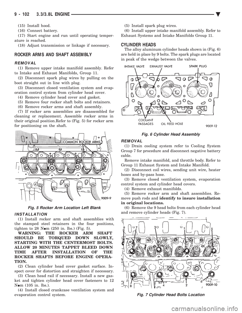
their original position.Refer to (Fig. 5) for rocker arm
for positioning on the shaft.
INSTALLATION
(1) Install rocker arm and shaft assemblies with
the stamped steel retainers in the four positions,
tighten to 28 N Im (250 in. lbs.) (Fig. 5).
WARNING: THE ROCKER ARM SHAFT
SHOULD BE TORQUED DOWN SLOWLY,
STARTING WITH THE CENTERMOST BOLTS.
ALLOW 20 MINUTES TAPPET BLEED DOWN
TIME AFTER INSTALLATION OF THE
ROCKER SHAFTS BEFORE ENGINE OPERA-
TION. (2) Clean cylinder head cover gasket surface. In-
spect cover for distortion and straighten if necessary. (3) Clean head rail if necessary. Install a new gas-
ket and tighten cylinder head cover fasteners to 12
N Im (105 in. lbs.).
(4) Install closed crankcase ventilation system and
evaporation control system. (5) Install spark plug wires.
(6) Install upper intake manifold assembly. Refer to
Exhaust Systems and Intake Manifolds Group 11.
CYLINDER HEADS
The alloy aluminum cylinder heads shown in (Fig. 6)
are held in place by 9 bolts. The spark plugs are located
in peak of the wedge between the valves.
REMOVAL
(1) Drain cooling system refer to Cooling System
Group 7 for procedure and disconnect negative battery
cable. Remove intake manifold, and throttle body. Refer to
Group 11 Exhaust System and Intake Manifold. (2) Disconnect coil wires, sending unit wire, heater
hoses and by-pass hose. (3) Remove closed ventilation system, evaporation
control system and cylinder head covers. (4) Remove exhaust manifolds.
(5) Remove rocker arm and shaft assemblies. Re-
move push rods and identify to insure installation
in original locations. (6) Remove the 9 head bolts from each cylinder head
and remove cylinder heads (Fig. 7).
Fig. 5 Rocker Arm Location Left Blank
Fig. 6 Cylinder Head Assembly
Fig. 7 Cylinder Head Bolts Location
9 - 102 3.3/3.8L ENGINE Ä
Page 1701 of 2438
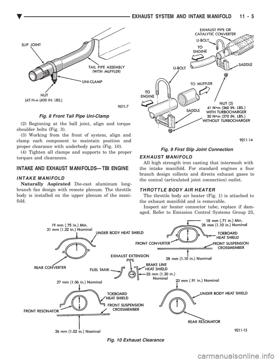
(2) Beginning at the ball joint, align and torque
shoulder bolts (Fig. 3). (3) Working from the front of system, align and
clamp each component to maintain position and
proper clearance with underbody parts (Fig. 10). (4) Tighten all clamps and supports to the proper
torques and clearances.
INTAKE AND EXHAUST MANIFOLDSÐTBI ENGINE
INTAKE MANIFOLD
Naturally Aspirated Die-cast aluminum long-
branch fan design with remote plenum. The throttle
body is installed on the upper plenum of the mani-
fold.
EXHAUST MANIFOLD
All high strength iron casting that intermesh with
the intake manifold. For standard engines a four
branch design collects and directs exhaust gases to
the conical (articulated joint connection) outlet.
THROTTLE BODY AIR HEATER
The throttle body air heater (Fig. 1) is attached to
the exhaust manifold and is removable. Inspect air heater connector tube; replace if dam-
aged. Refer to Emission Control Systems Group 25,
Fig. 9 First Slip Joint Connection
Fig. 10 Exhaust Clearance
Fig. 8 Front Tail Pipe Uni-Clamp
Ä EXHAUST SYSTEM AND INTAKE MANIFOLD 11 - 5
Page 1702 of 2438
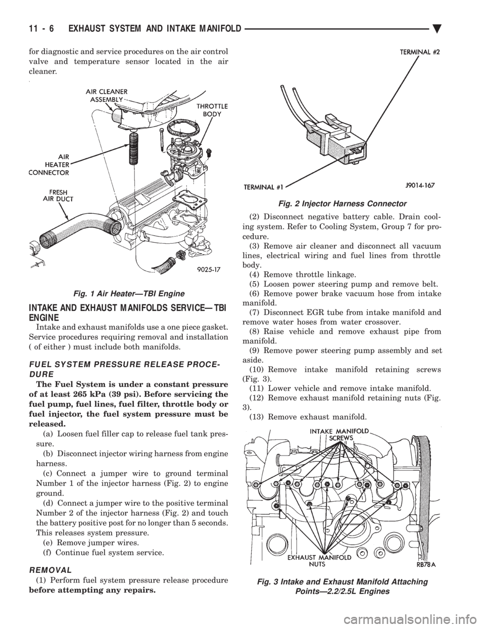
for diagnostic and service procedures on the air control
valve and temperature sensor located in the air
cleaner.
INTAKE AND EXHAUST MANIFOLDS SERVICEÐTBI
ENGINE
Intake and exhaust manifolds use a one piece gasket.
Service procedures requiring removal and installation
( of either ) must include both manifolds.
FUEL SYSTEM PRESSURE RELEASE PROCE- DURE
The Fuel System is under a constant pressure
of at least 265 kPa (39 psi). Before servicing the
fuel pump, fuel lines, fuel filter, throttle body or
fuel injector, the fuel system pressure must be
released. (a) Loosen fuel filler cap to release fuel tank pres-
sure. (b) Disconnect injector wiring harness from engine
harness. (c) Connect a jumper wire to ground terminal
Number 1 of the injector harness (Fig. 2) to engine
ground. (d) Connect a jumper wire to the positive terminal
Number 2 of the injector harness (Fig. 2) and touch
the battery positive post for no longer than 5 seconds.
This releases system pressure. (e) Remove jumper wires.
(f) Continue fuel system service.
REMOVAL
(1) Perform fuel system pressure release procedure
before attempting any repairs. (2) Disconnect negative battery cable. Drain cool-
ing system. Refer to Cooling System, Group 7 for pro-
cedure. (3) Remove air cleaner and disconnect all vacuum
lines, electrical wiring and fuel lines from throttle
body. (4) Remove throttle linkage.
(5) Loosen power steering pump and remove belt.
(6) Remove power brake vacuum hose from intake
manifold. (7) Disconnect EGR tube from intake manifold and
remove water hoses from water crossover. (8) Raise vehicle and remove exhaust pipe from
manifold. (9) Remove power steering pump assembly and set
aside. (10) Remove intake manifold retaining screws
(Fig. 3). (11) Lower vehicle and remove intake manifold.
(12) Remove exhaust manifold retaining nuts (Fig.
3). (13) Remove exhaust manifold.
Fig. 2 Injector Harness Connector
Fig. 3 Intake and Exhaust Manifold Attaching PointsÐ2.2/2.5L Engines
Fig. 1 Air HeaterÐTBI Engine
11 - 6 EXHAUST SYSTEM AND INTAKE MANIFOLD Ä
Page 1711 of 2438
(e) Remove jumper wires.
(f) Continue fuel system service.
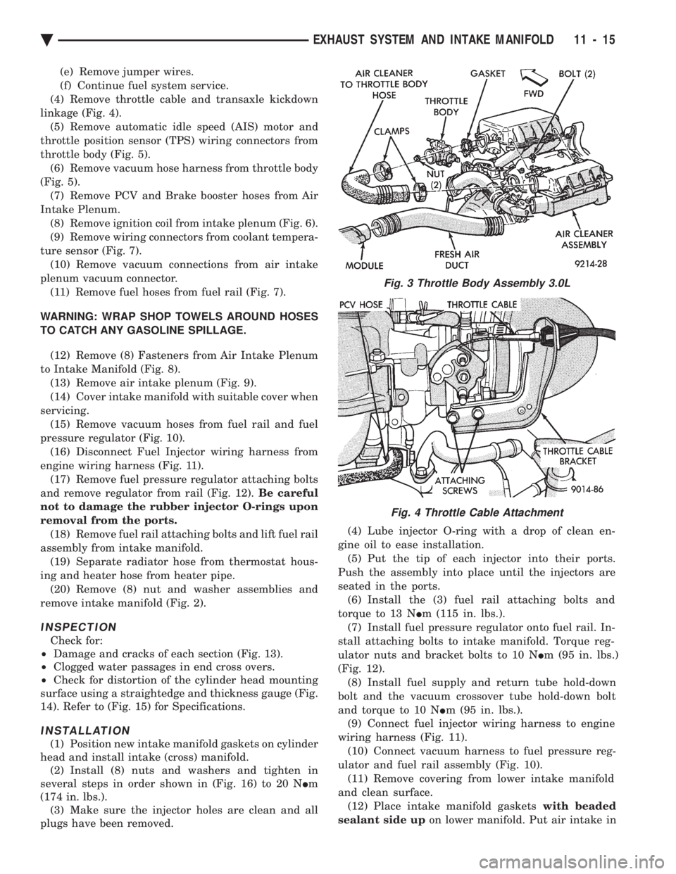
(4) Remove throttle cable and transaxle kickdown
linkage (Fig. 4). (5) Remove automatic idle speed (AIS) motor and
throttle position sensor (TPS) wiring connectors from
throttle body (Fig. 5). (6) Remove vacuum hose harness from throttle body
(Fig. 5). (7) Remove PCV and Brake booster hoses from Air
Intake Plenum. (8) Remove ignition coil from intake plenum (Fig. 6).
(9) Remove wiring connectors from coolant tempera-
ture sensor (Fig. 7). (10) Remove vacuum connections from air intake
plenum vacuum connector. (11) Remove fuel hoses from fuel rail (Fig. 7).
WARNING: WRAP SHOP TOWELS AROUND HOSES
TO CATCH ANY GASOLINE SPILLAGE. (12) Remove (8) Fasteners from Air Intake Plenum
to Intake Manifold (Fig. 8). (13) Remove air intake plenum (Fig. 9).
(14) Cover intake manifold with suitable cover when
servicing. (15) Remove vacuum hoses from fuel rail and fuel
pressure regulator (Fig. 10). (16) Disconnect Fuel Injector wiring harness from
engine wiring harness (Fig. 11). (17) Remove fuel pressure regulator attaching bolts
and remove regulator from rail (Fig. 12). Be careful
not to damage the rubber injector O-rings upon
removal from the ports. (18) Remove fuel rail attaching bolts and lift fuel rail
assembly from intake manifold. (19) Separate radiator hose from thermostat hous-
ing and heater hose from heater pipe. (20) Remove (8) nut and washer assemblies and
remove intake manifold (Fig. 2).
INSPECTION
Check for:
² Damage and cracks of each section (Fig. 13).
² Clogged water passages in end cross overs.
² Check for distortion of the cylinder head mounting
surface using a straightedge and thickness gauge (Fig.
14). Refer to (Fig. 15) for Specifications.
INSTALLATION
(1) Position new intake manifold gaskets on cylinder
head and install intake (cross) manifold. (2) Install (8) nuts and washers and tighten in
several steps in order shown in (Fig. 16) to 20 N Im
(174 in. lbs.). (3) Make sure the injector holes are clean and all
plugs have been removed. (4) Lube injector O-ring with a drop of clean en-
gine oil to ease installation. (5) Put the tip of each injector into their ports.
Push the assembly into place until the injectors are
seated in the ports. (6) Install the (3) fuel rail attaching bolts and
torque to 13 N Im (115 in. lbs.).
(7) Install fuel pressure regulator onto fuel rail. In-
stall attaching bolts to intake manifold. Torque reg-
ulator nuts and bracket bolts to 10 N Im (95 in. lbs.)
(Fig. 12). (8) Install fuel supply and return tube hold-down
bolt and the vacuum crossover tube hold-down bolt
and torque to 10 N Im (95 in. lbs.).
(9) Connect fuel injector wiring harness to engine
wiring harness (Fig. 11). (10) Connect vacuum harness to fuel pressure reg-
ulator and fuel rail assembly (Fig. 10). (11) Remove covering from lower intake manifold
and clean surface. (12) Place intake manifold gaskets with beaded
sealant side up on lower manifold. Put air intake in
Fig. 3 Throttle Body Assembly 3.0L
Fig. 4 Throttle Cable Attachment
Ä EXHAUST SYSTEM AND INTAKE MANIFOLD 11 - 15
Page 1712 of 2438
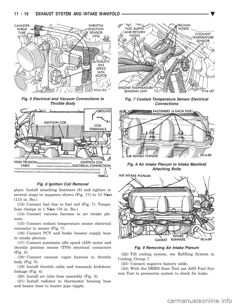
place. Install attaching fasteners (8) and tighten in
several steps in sequence shown (Fig. 17) to 13 N Im
(115 in. lbs.). (13) Connect fuel line to fuel rail (Fig. 7). Torque
hose clamps to 1 N Im (10 in. lbs.).
(14) Connect vacuum harness to air intake ple-
num. (15) Connect coolant temperature sensor electrical
connector to sensor (Fig. 7). (16) Connect PCV and brake booster supply hose
to intake plenum. (17) Connect automatic idle speed (AIS) motor and
throttle position sensor (TPS) electrical connectors
(Fig. 5). (18) Connect vacuum vapor harness to throttle
body (Fig. 5). (19) Install throttle cable and transaxle kickdown
linkage (Fig. 4). (20) Install air inlet hose assembly (Fig. 3).
(21) Install radiator to thermostat housing hose
and heater hose to heater pipe nipple. (22) Fill cooling system, see Refilling System in
Cooling, Group 7. (23) Connect negative battery cable.
(24) With the DRBII Scan Tool use ASD Fuel Sys-
tem Test to pressurize system to check for leaks.
Fig. 5 Electrical and Vacuum Connections to Throttle Body
Fig. 6 Ignition Coil Removal
Fig. 7 Coolant Temperature Sensor Electrical Connections
Fig. 8 Air Intake Plenum to Intake ManifoldAttaching Bolts
Fig. 9 Removing Air Intake Plenum
11 - 16 EXHAUST SYSTEM AND INTAKE MANIFOLD Ä