1993 CHEVROLET PLYMOUTH ACCLAIM heater
[x] Cancel search: heaterPage 2310 of 2438
HEATER AND A/C PERFORMANCE TESTS
HEATER OUTPUT TEST
PRE-DIAGNOSTIC PREPARATIONS
Review Safety Precautions and Warnings before
performing the following procedures. Check the radiator coolant level, drive belt tension,
and engine vacuum line connections. Also check ra-
diator air flow and radiator fan operation. Start en-
gine and allow to warm up to normal operating
temperature.
WARNING: DO NOT REMOVE RADIATOR CAP
WHEN ENGINE IS HOT, PERSONAL INJURY CAN
RESULT.
If vehicle has been run recently, wait 15 minutes
before removing cap. Place a rag over the cap and
turn it to the first safety stop. Allow pressure to es-
cape through the overflow tube. When the system
stabilizes, remove the cap completely.
MAXIMUM HEATER OUTPUT: TEST AND ACTION
Engine coolant is provided to the heater system by
two 16 mm (5/8 inch inside diameter) heater hoses.
With engine idling at normal running temperature,
set the control to maximum heat, floor, and high
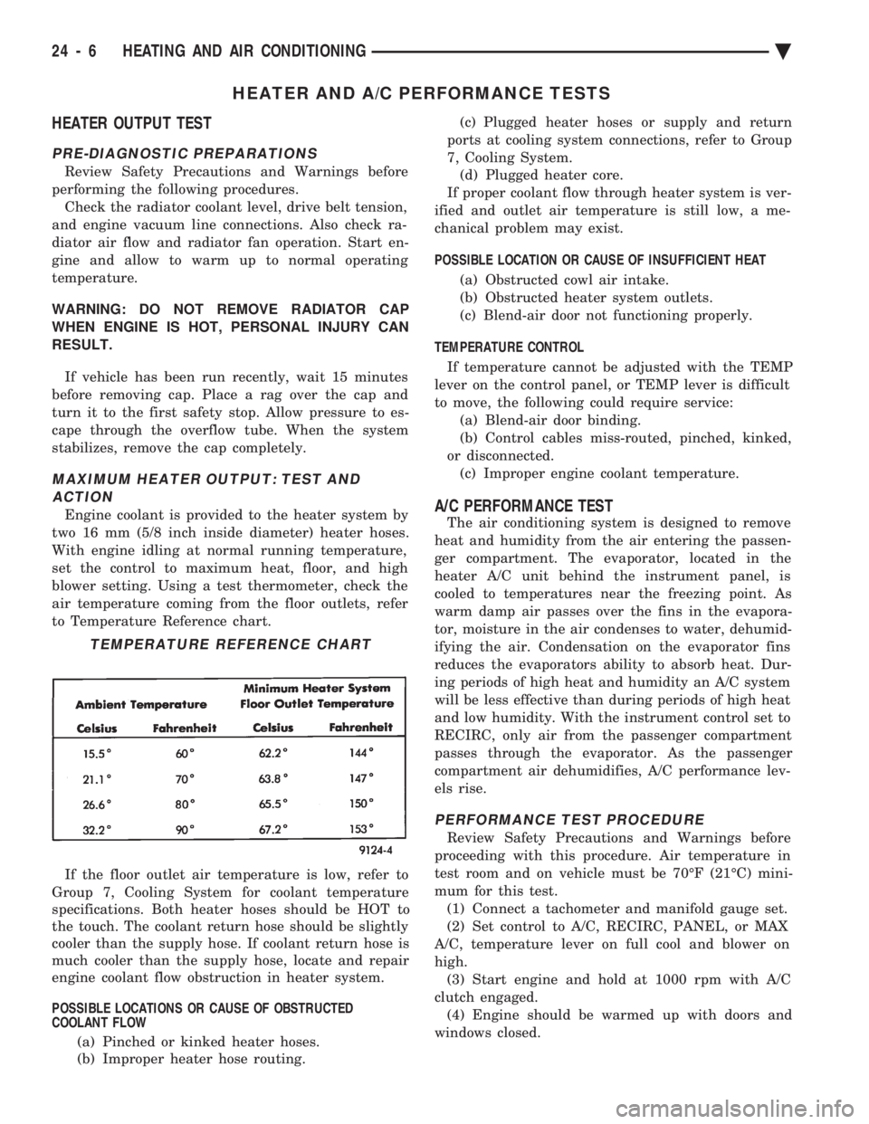
blower setting. Using a test thermometer, check the
air temperature coming from the floor outlets, refer
to Temperature Reference chart.
If the floor outlet air temperature is low, refer to
Group 7, Cooling System for coolant temperature
specifications. Both heater hoses should be HOT to
the touch. The coolant return hose should be slightly
cooler than the supply hose. If coolant return hose is
much cooler than the supply hose, locate and repair
engine coolant flow obstruction in heater system.
POSSIBLE LOCATIONS OR CAUSE OF OBSTRUCTED
COOLANT FLOW
(a) Pinched or kinked heater hoses.
(b) Improper heater hose routing. (c) Plugged heater hoses or supply and return
ports at cooling system connections, refer to Group
7, Cooling System. (d) Plugged heater core.
If proper coolant flow through heater system is ver-
ified and outlet air temperature is still low, a me-
chanical problem may exist.
POSSIBLE LOCATION OR CAUSE OF INSUFFICIENT HEAT
(a) Obstructed cowl air intake.
(b) Obstructed heater system outlets.
(c) Blend-air door not functioning properly.
TEMPERATURE CONTROL If temperature cannot be adjusted with the TEMP
lever on the control panel, or TEMP lever is difficult
to move, the following could require service: (a) Blend-air door binding.
(b) Control cables miss-routed, pinched, kinked,
or disconnected. (c) Improper engine coolant temperature.A/C PERFORMANCE TEST
The air conditioning system is designed to remove
heat and humidity from the air entering the passen-
ger compartment. The evaporator, located in the
heater A/C unit behind the instrument panel, is
cooled to temperatures near the freezing point. As
warm damp air passes over the fins in the evapora-
tor, moisture in the air condenses to water, dehumid-
ifying the air. Condensation on the evaporator fins
reduces the evaporators ability to absorb heat. Dur-
ing periods of high heat and humidity an A/C system
will be less effective than during periods of high heat
and low humidity. With the instrument control set to
RECIRC, only air from the passenger compartment
passes through the evaporator. As the passenger
compartment air dehumidifies, A/C performance lev-
els rise.
PERFORMANCE TEST PROCEDURE
Review Safety Precautions and Warnings before
proceeding with this procedure. Air temperature in
test room and on vehicle must be 70ÉF (21ÉC) mini-
mum for this test. (1) Connect a tachometer and manifold gauge set.
(2) Set control to A/C, RECIRC, PANEL, or MAX
A/C, temperature lever on full cool and blower on
high. (3) Start engine and hold at 1000 rpm with A/C
clutch engaged. (4) Engine should be warmed up with doors and
windows closed.
TEMPERATURE REFERENCE CHART
24 - 6 HEATING AND AIR CONDITIONING Ä
Page 2316 of 2438
WARNING: REVIEW SAFETY PRECAUTIONS AND
WARNINGS BEFORE CHARGING THE REFRIGER-
ANT SYSTEM.
After the system has been tested for leaks and
evacuated, a refrigerant charge can be injected into
the system. (1) Connect manifold gauge set.
(2) Measure refrigerant (refer to capacities) and
heat to 52ÉC (125ÉF) with the charging station. Refer
to the instructions provided with the equipment be-
ing used.
REFRIGERANT CAPACITIES:
² Without Rear A/C = 907 g (32 oz.)
² With Rear A/C = 1219 g (43 oz.)
(3) Open the suction and discharge valves. Open
the charge valve to allow the heated refrigerant to
flow into the system. When the transfer of refriger-
ant has stopped, close the suction and discharge
valve. (4) If all of the refrigerant charge did not transfer
from the dispensing device, start engine and hold at
idle (1400 rpm). Set the A/C control to A/C, low
blower speed, and open windows. If the A/C compres-
sor does not engage, test the compressor clutch con-
trol circuit and correct any failure. Refer to Group
8W, Wiring Diagrams. (5) Open the suction valve to allow the remaining
refrigerant to transfer to the system.
WARNING: TAKE CARE NOT TO OPEN THE DIS-
CHARGE (HIGH-PRESSURE) VALVE AT THIS TIME.
(6) Close all valves and test the A/C system perfor-
mance. Refer to Heater and A/C Performance Tests
in this Group. (7) Disconnect the charging station or manifold
gauge set. Install the service port caps.
OIL LEVEL
It is important to have the correct amount of oil in
the A/C system to ensure proper lubrication of the
compressor. Too little oil will result in damage to the
compressor. Too much oil will reduce the cooling ca-
pacity of the system. The oil used in the compressor is a 500 SUS viscos-
ity, wax-free refrigerant oil. Only refrigerant oil of
the same type should be used to service the system.
Do not use any other oil. The oil container should be
kept tightly capped until it is ready for use, and then
tightly capped after use to prevent contamination
from dirt and moisture. Refrigerant oil will quickly
absorb any moisture it comes in contact with. It will not be necessary to check oil level in the
compressor or to add oil unless there has been an oil
loss. This may be due to a ruptured line, shaft seal leakage, leakage from the evaporator, condenser
leak, filter drier or loss of refrigerant due to a colli-
sion. Oil loss at a the leak point will be evident by
the presence of a wet, shiny surface around the leak.
REFRIGERANT OIL LEVEL CHECK
When an A/C system is assembled at the factory,
all components (except the compressor) are refriger-
ant oil free. After the system has been charged with
R-12 and operated, the oil in the compressor is dis-
persed through the lines and components. The evap-
orator, condenser, and filter-drier will retain a
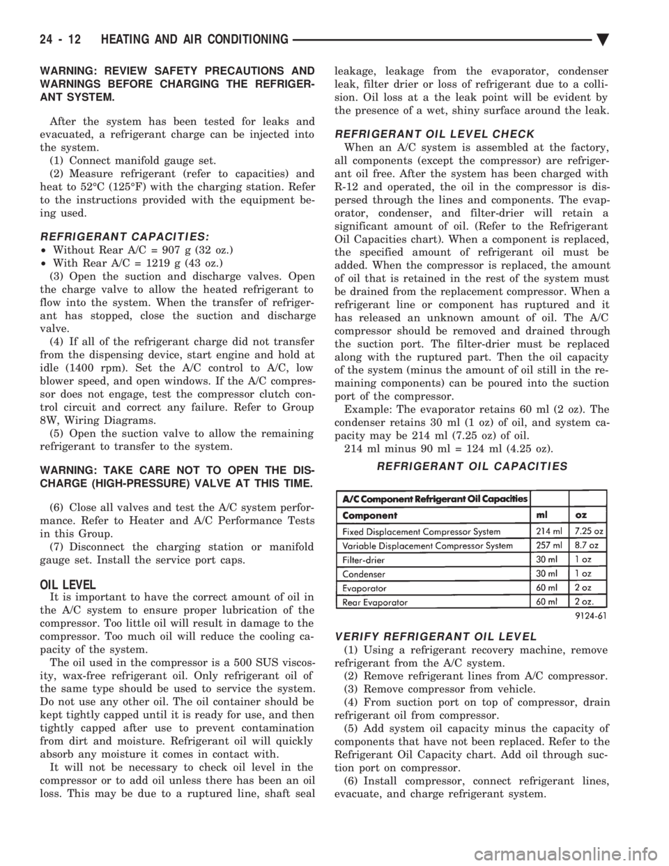
significant amount of oil. (Refer to the Refrigerant
Oil Capacities chart). When a component is replaced,
the specified amount of refrigerant oil must be
added. When the compressor is replaced, the amount
of oil that is retained in the rest of the system must
be drained from the replacement compressor. When a
refrigerant line or component has ruptured and it
has released an unknown amount of oil. The A/C
compressor should be removed and drained through
the suction port. The filter-drier must be replaced
along with the ruptured part. Then the oil capacity
of the system (minus the amount of oil still in the re-
maining components) can be poured into the suction
port of the compressor. Example: The evaporator retains 60 ml (2 oz). The
condenser retains 30 ml (1 oz) of oil, and system ca-
pacity may be 214 ml (7.25 oz) of oil. 214 ml minus 90 ml = 124 ml (4.25 oz).
VERIFY REFRIGERANT OIL LEVEL
(1) Using a refrigerant recovery machine, remove
refrigerant from the A/C system. (2) Remove refrigerant lines from A/C compressor.
(3) Remove compressor from vehicle.
(4) From suction port on top of compressor, drain
refrigerant oil from compressor. (5) Add system oil capacity minus the capacity of
components that have not been replaced. Refer to the
Refrigerant Oil Capacity chart. Add oil through suc-
tion port on compressor. (6) Install compressor, connect refrigerant lines,
evacuate, and charge refrigerant system.
REFRIGERANT OIL CAPACITIES
24 - 12 HEATING AND AIR CONDITIONING Ä
Page 2317 of 2438
VARIABLE DISPLACEMENT COMPRESSORÐMODEL 6C17 INDEX
page page
Clutch Coil Tests ......................... 17
Compressor ............................. 17
Compressor Clutch Inoperative .............. 13
Compressor Clutch/Coil Assembly ............ 19
Compressor Diagnosis ..................... 13
Compressor Front Shaft Seal ............... 20 Compressor High Pressure Cut-Out Switch
..... 21
Compressor High Pressure Relief Valve (HPR) . . 22
Compressor Identification ................... 13
Compressor Main or Sub Control Valves ....... 22
Compressor Noise ........................ 13
General Information ....................... 13
GENERAL INFORMATION
The Variable Displacement Compressor (VDC) pro-
vides maximum A/C performance under most condi-
tions. It is designed to operate continuously without
any cycling of the compressor clutch. The compressor
has a variable angle wobble plate with six axially
oriented cylinders. During vehicle A/C system operation, the compres-
sor will change its displacement to match the vehi-
cles A/C cooling demands. When the A/C system
needs more cooling capacity, the compressor will in-
crease its pumping capacity. This is done by increas-
ing the wobble plate angle to increase the piston
stroke. When the A/C system cooling demand is low,
the compressor will decrease its pumping capacity by
reducing the piston pumping stroke. The low cooling
capacity will prevent evaporator from freezing.
COMPRESSOR IDENTIFICATION
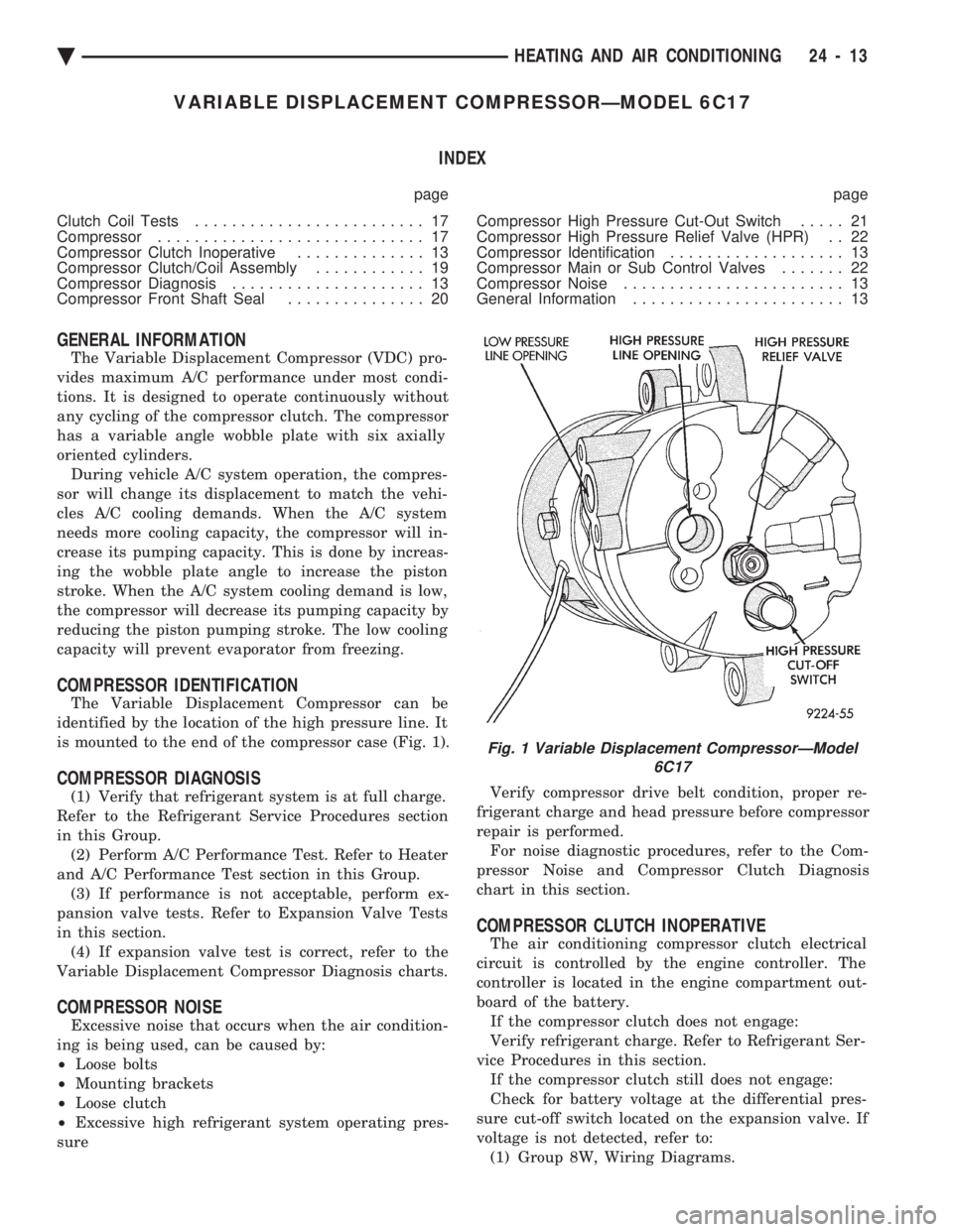
The Variable Displacement Compressor can be
identified by the location of the high pressure line. It
is mounted to the end of the compressor case (Fig. 1).
COMPRESSOR DIAGNOSIS
(1) Verify that refrigerant system is at full charge.
Refer to the Refrigerant Service Procedures section
in this Group. (2) Perform A/C Performance Test. Refer to Heater
and A/C Performance Test section in this Group. (3) If performance is not acceptable, perform ex-
pansion valve tests. Refer to Expansion Valve Tests
in this section. (4) If expansion valve test is correct, refer to the
Variable Displacement Compressor Diagnosis charts.
COMPRESSOR NOISE
Excessive noise that occurs when the air condition-
ing is being used, can be caused by:
² Loose bolts
² Mounting brackets
² Loose clutch
² Excessive high refrigerant system operating pres-
sure Verify compressor drive belt condition, proper re-
frigerant charge and head pressure before compressor
repair is performed. For noise diagnostic procedures, refer to the Com-
pressor Noise and Compressor Clutch Diagnosis
chart in this section.
COMPRESSOR CLUTCH INOPERATIVE
The air conditioning compressor clutch electrical
circuit is controlled by the engine controller. The
controller is located in the engine compartment out-
board of the battery. If the compressor clutch does not engage:
Verify refrigerant charge. Refer to Refrigerant Ser-
vice Procedures in this section. If the compressor clutch still does not engage:
Check for battery voltage at the differential pres-
sure cut-off switch located on the expansion valve. If
voltage is not detected, refer to: (1) Group 8W, Wiring Diagrams.
Fig. 1 Variable Displacement CompressorÐModel 6C17
Ä HEATING AND AIR CONDITIONING 24 - 13
Page 2351 of 2438
COMPONENT SERVICE PROCEDURES INDEX
page page
Air Distribution Duct ...................... 50
Air Distribution Duct ...................... 52
Ambient Switch .......................... 47
Blend-Air Door .......................... 64
Blower Motor ............................ 58
Blower Motor Wheel Assembly .............. 58
Blower Resistor Block ..................... 49
Condensate Drain Tube ................... 64
Condenser Assembly ...................... 57
Condenser Fan Control Switch .............. 47
Defroster Duct ........................... 51
Defroster Duct Adapter .................... 51
Defroster Ducts/Demister Ducts and Hoses ..... 52
Differential Pressure Cut-Out Switch Diagnosis . . 48
Evaporator Coil .......................... 64 Expansion Valve
......................... 55
Filter-Drier Assembly ...................... 57
Fin-Sensing Cycling Clutch Switch ............ 53
Heater Core ............................ 64
Heater Hoses ........................... 51
Heater-A/C Unit AssemblyÐRemoval and Installation ............................ 61
Heater-A/C Unit Recondition ................ 63
Low or Differential Pressure Cut-Off Switch ..... 54
Temperature Control CableÐAA,AP,AG and AJ Models ............................ 49
Temperature Control CableÐAC/AY Models .... 48
Vacuum ActuatorÐFresh/Recirc Door ......... 50
Vacuum ActuatorsÐMode Doors ............. 52
AMBIENT SWITCH
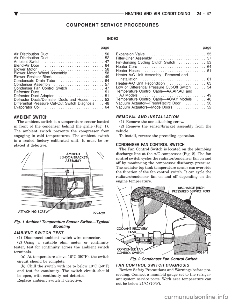
The ambient switch is a temperature sensor located
in front of the condenser behind the grille (Fig. 1).
The ambient switch prevents the compressor from
engaging in cold temperatures. The ambient switch
is a sealed factory calibrated unit. It must be re-
placed if defective.
AMBIENT SWITCH TEST
(1) Disconnect ambient switch wire connector.
(2) Using a suitable ohm meter or continuity
tester, test for continuity across the ambient switch
terminals. (a) At temperature above 10ÉC (50ÉF), the switch
circuit should be complete. (b) Chill the switch with ice to below 10ÉC (50ÉF)
and test for continuity. The switch circuit should
be open, with continuity not detected.
Replace ambient switch if defective.
REMOVAL AND INSTALLATION
(1) Remove the one attaching screw.
(2) Remove the sensor/bracket assembly from the
vehicle. To install, reverse the preceding operation.
CONDENSER FAN CONTROL SWITCH
The Fan Control Switch is located on the plumbing
discharge line at the A/C compressor (Fig. 2). The fan
control switch cycles the radiator/condenser fan on and
off by monitoring the compressor discharge pressure.
The radiator top tank temperature sensor can over ride
the function of the fan control switch. It can cycle the
radiator/condenser fan on and off depending on the
engine temperature.
FAN CONTROL SWITCH DIAGNOSIS
Review Safety Precautions and Warnings before pro-
ceeding. Connect a manifold gauge set to the refriger-
ant system service ports. Work area temperature can
not be below 21ÉC (70ÉF).
Fig. 1 Ambient Temperature Sensor SwitchÐTypical Mounting
Fig. 2 Condenser Fan Control Switch
Ä HEATING AND AIR CONDITIONING 24 - 47
Page 2352 of 2438
WARNING: AVOID RADIATOR/CONDENSER FAN
BLADES WHEN WORKING IN THE RADIATOR
AREA. FAN IS CONTROLLED BY TEMPERATURE
AND CAN START ANY TIME IGNITION IS ON. PER-
SONAL INJURY CAN RESULT.
(1) Disconnect fan control switch wire connector.
(2) Using a suitable jumper wire, jump across ter-
minals in wire connector. (3) Connect a suitable continuity tester across fan
control switch terminals. (4) Start engine and set idle at 1300 rpm. The ra-
diator fan should run constantly. (5) Set the A/C controls to A/C and high blower.
(6) If the high pressure gauge reads below 1102
kPa (160 psi) there should be no continuity across
the switch terminals.
CAUTION: Do not allow engine to overheat when ra-
diator air flow is blocked.
(7) Block radiator air flow with a suitable cover to
increase the high side pressure to at least 1585 kPa
(230 psi). Electrical continuity should be detected
across the fan control switch terminals. (8) Remove cover from front of vehicle to allow
high side pressure to decrease. When pressure drops
below 1102 kPa (160 psi), continuity should cease. If fan control switch is defective, replace it.
REMOVAL AND INSTALLATION
CAUTION: Refrigerant removal is not necessary
when removing the Condenser Fan Control Switch.
However, a small amount of refrigerant will vent
from the switch port. Review the refrigerant han-
dling section of Safety Precautions and Warnings in
the General Information section of this Group.
(1) Disconnect wire connector from condenser fan
control switch. (2) Loosen and quickly rotate the switch counter-
clockwise and separate from the high pressure line
switch port. To install, reverse the preceding operation.
DIFFERENTIAL PRESSURE CUT-OUT SWITCH
DIAGNOSIS
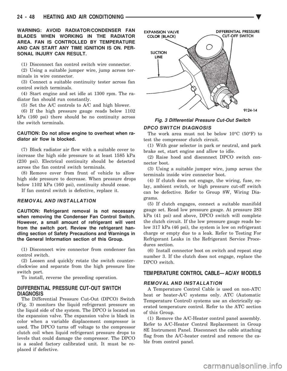
The Differential Pressure Cut-Out (DPCO) Switch
(Fig. 3) monitors the liquid refrigerant pressure on
the liquid side of the system. The DPCO is located on
the expansion valve. The expansion valve is black in
color when a variable displacement compressor is
used. The DPCO turns off voltage to the compressor
clutch coil when liquid refrigerant pressure drops to
levels that could damage the compressor. The DPCO
is a sealed factory calibrated unit. It must be re-
placed if defective.
DPCO SWITCH DIAGNOSIS
The work area must not be below 10ÉC (50ÉF) to
test the compressor clutch circuit. (1) With gear selector in park or neutral, and park
brake set, start engine and allow to idle. (2) Raise hood and disconnect DPCO switch con-
nector boot. (3) Using a suitable jumper wire, jump across the
terminals inside wire connector boot. (4) If clutch does not engage, the wiring, fuse, re-
lay, ambient switch, or high pressure cut-off switch
can be defective. Refer to Group 8W, Wiring Dia-
grams. (5) If clutch engages, connect a suitable manifold
gauge set. Read low pressure gauge. At pressure 283
kPa (41 psi) and above, DPCO switch will complete
the clutch circuit. If the low pressure gauge reads be-
low 317 kPa (46 psi), the system is low on refrigerant
charge or empty due to a leak. Refer to Testing For
Refrigerant Leaks in the Refrigerant Service Proce-
dures section. (6) Install connector boot on switch and repeat step
number 3. If the clutch does not engage, replace the
DPCO switch.
TEMPERATURE CONTROL CABLEÐAC/AY MODELS
REMOVAL AND INSTALLATION
A Temperature Control Cable is used on non-ATC
heat or heater-A/C systems only. ATC (Automatic
Temperature Control) systems use an electrically op-
erated temperature control. Refer to the ATC section
of this Group. (1) Remove the A/C-Heater control panel assembly.
Refer to A/C-Heater Control Replacement in Group
8E Instrument Panel. Disconnect the cable attaching
flag from the A/C-heater control and remove the ca-
ble from control panel.
Fig. 3 Differential Pressure Cut-Out Switch
24 - 48 HEATING AND AIR CONDITIONING Ä
Page 2353 of 2438
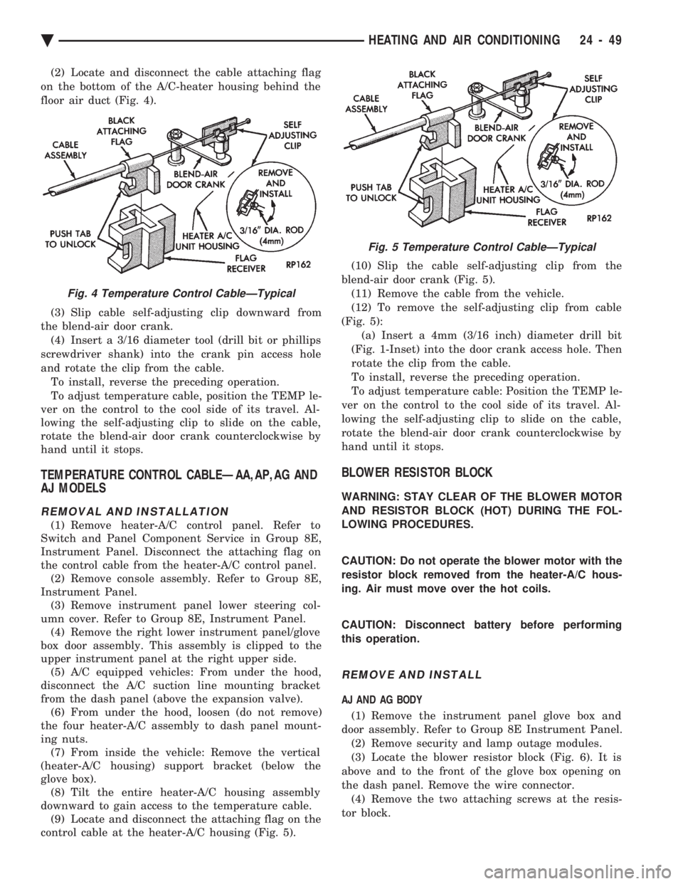
(2) Locate and disconnect the cable attaching flag
on the bottom of the A/C-heater housing behind the
floor air duct (Fig. 4).
(3) Slip cable self-adjusting clip downward from
the blend-air door crank. (4) Insert a 3/16 diameter tool (drill bit or phillips
screwdriver shank) into the crank pin access hole
and rotate the clip from the cable. To install, reverse the preceding operation.
To adjust temperature cable, position the TEMP le-
ver on the control to the cool side of its travel. Al-
lowing the self-adjusting clip to slide on the cable,
rotate the blend-air door crank counterclockwise by
hand until it stops.
TEMPERATURE CONTROL CABLEÐAA,AP,AG AND
AJ MODELS
REMOVAL AND INSTALLATION
(1) Remove heater-A/C control panel. Refer to
Switch and Panel Component Service in Group 8E,
Instrument Panel. Disconnect the attaching flag on
the control cable from the heater-A/C control panel. (2) Remove console assembly. Refer to Group 8E,
Instrument Panel. (3) Remove instrument panel lower steering col-
umn cover. Refer to Group 8E, Instrument Panel. (4) Remove the right lower instrument panel/glove
box door assembly. This assembly is clipped to the
upper instrument panel at the right upper side. (5) A/C equipped vehicles: From under the hood,
disconnect the A/C suction line mounting bracket
from the dash panel (above the expansion valve). (6) From under the hood, loosen (do not remove)
the four heater-A/C assembly to dash panel mount-
ing nuts. (7) From inside the vehicle: Remove the vertical
(heater-A/C housing) support bracket (below the
glove box). (8) Tilt the entire heater-A/C housing assembly
downward to gain access to the temperature cable. (9) Locate and disconnect the attaching flag on the
control cable at the heater-A/C housing (Fig. 5). (10) Slip the cable self-adjusting clip from the
blend-air door crank (Fig. 5). (11) Remove the cable from the vehicle.
(12) To remove the self-adjusting clip from cable
(Fig. 5): (a) Insert a 4mm (3/16 inch) diameter drill bit
(Fig. 1-Inset) into the door crank access hole. Then
rotate the clip from the cable.
To install, reverse the preceding operation.
To adjust temperature cable: Position the TEMP le-
ver on the control to the cool side of its travel. Al-
lowing the self-adjusting clip to slide on the cable,
rotate the blend-air door crank counterclockwise by
hand until it stops.
BLOWER RESISTOR BLOCK
WARNING: STAY CLEAR OF THE BLOWER MOTOR
AND RESISTOR BLOCK (HOT) DURING THE FOL-
LOWING PROCEDURES.
CAUTION: Do not operate the blower motor with the
resistor block removed from the heater-A/C hous-
ing. Air must move over the hot coils.
CAUTION: Disconnect battery before performing
this operation.
REMOVE AND INSTALL
AJ AND AG BODY
(1) Remove the instrument panel glove box and
door assembly. Refer to Group 8E Instrument Panel. (2) Remove security and lamp outage modules.
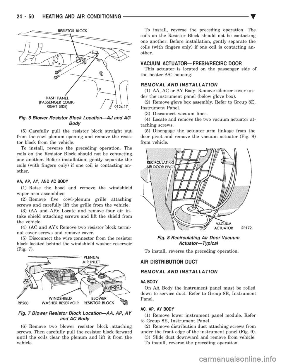
(3) Locate the blower resistor block (Fig. 6). It is
above and to the front of the glove box opening on
the dash panel. Remove the wire connector. (4) Remove the two attaching screws at the resis-
tor block.
Fig. 4 Temperature Control CableÐTypical
Fig. 5 Temperature Control CableÐTypical
Ä HEATING AND AIR CONDITIONING 24 - 49
Page 2354 of 2438
(5) Carefully pull the resistor block straight out
from the cowl plenum opening and remove the resis-
tor block from the vehicle. To install, reverse the preceding operation. The
coils on the Resistor Block should not be contacting
one another. Before installation, gently separate the
coils (with fingers only) if one coil is contacting an-
other.
AA, AP, AY, AND AC BODY
(1) Raise the hood and remove the windshield
wiper arm assemblies. (2) Remove five cowl-plenum grille attaching
screws and carefully lift the grille from the vehicle. (3) (AA and AP): Locate and remove four air in-
take shield attaching screws and lift the shield from
the vehicle. (4) (AC and AY): Remove two resistor block termi-
nal cover screws and remove cover. (5) Disconnect the wire connector from the resistor
block located behind the windshield washer reservoir
(Fig. 7).
(6) Remove two blower resistor block attaching
screws. Then carefully pull the resistor block forward
until the coils clear the plenum and lift it from the
vehicle. To install, reverse the preceding operation. The
coils on the Resistor Block should not be contacting
one another. Before installation, gently separate the
coils (with fingers only) if one coil is contacting an-
other.
VACUUM ACTUATORÐFRESH/RECIRC DOOR
This actuator is located on the passenger side of
the heater-A/C housing.
REMOVAL AND INSTALLATION
(1) AA, AC or AY Body: Remove silencer cover un-
der the instrument panel (below glove box). (2) Remove glove box assembly. Refer to Group 8E,
Instrument Panel. (3) Disconnect vacuum lines.
(4) Locate and remove the two vacuum actuator at-
taching screws. (5) Disengage the actuator arm linkage from the
door pivot and remove the vacuum actuator (Fig. 8)
from vehicle.
To install, reverse the preceding operation.
AIR DISTRIBUTION DUCT
REMOVAL AND INSTALLATION
AA BODY On AA Body the instrument panel must be rolled
down to service duct. Refer to Group 8E, Instrument
Panel.
AC, AP, AY BODY (1) Remove lower instrument panel module. Refer
to Group 8E, Instrument Panel. (2) Remove distribution duct attaching screws from
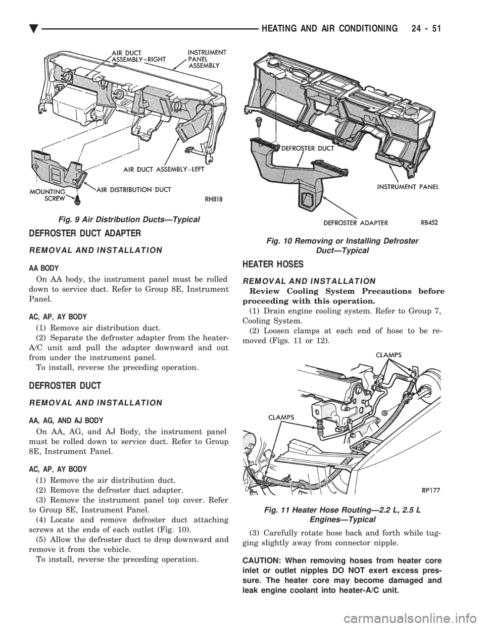
under the front edge of the instrument panel (Fig. 9). (3) Slide duct downward and remove from vehicle.
To install, reverse the preceding operation.
Fig. 6 Blower Resistor Block LocationÐAJ and AG Body
Fig. 7 Blower Resistor Block LocationÐAA, AP, AYand AC Body
Fig. 8 Recirculating Air Door VacuumActuatorÐTypical
24 - 50 HEATING AND AIR CONDITIONING Ä
Page 2355 of 2438
DEFROSTER DUCT ADAPTER
REMOVAL AND INSTALLATION
AA BODY On AA body, the instrument panel must be rolled
down to service duct. Refer to Group 8E, Instrument
Panel.
AC, AP, AY BODY
(1) Remove air distribution duct.
(2) Separate the defroster adapter from the heater-
A/C unit and pull the adapter downward and out
from under the instrument panel. To install, reverse the preceding operation.
DEFROSTER DUCT
REMOVAL AND INSTALLATION
AA, AG, AND AJ BODY
On AA, AG, and AJ Body, the instrument panel
must be rolled down to service duct. Refer to Group
8E, Instrument Panel.
AC, AP, AY BODY
(1) Remove the air distribution duct.
(2) Remove the defroster duct adapter.
(3) Remove the instrument panel top cover. Refer
to Group 8E, Instrument Panel. (4) Locate and remove defroster duct attaching
screws at the ends of each outlet (Fig. 10). (5) Allow the defroster duct to drop downward and
remove it from the vehicle. To install, reverse the preceding operation.
HEATER HOSES
REMOVAL AND INSTALLATION
Review Cooling System Precautions before
proceeding with this operation. (1) Drain engine cooling system. Refer to Group 7,
Cooling System. (2) Loosen clamps at each end of hose to be re-
moved (Figs. 11 or 12).
(3) Carefully rotate hose back and forth while tug-
ging slightly away from connector nipple.
CAUTION: When removing hoses from heater core
inlet or outlet nipples DO NOT exert excess pres-
sure. The heater core may become damaged and
leak engine coolant into heater-A/C unit.
Fig. 9 Air Distribution DuctsÐTypical
Fig. 10 Removing or Installing Defroster DuctÐTypical
Fig. 11 Heater Hose RoutingÐ2.2 L, 2.5 LEnginesÐTypical
Ä HEATING AND AIR CONDITIONING 24 - 51