1993 CHEVROLET PLYMOUTH ACCLAIM display
[x] Cancel search: displayPage 437 of 2438

AP BODY INDEX
page page
Ambient Temperature Sensor Removal ........ 25
Compass Calibration ...................... 21
Compass Diagnostics ..................... 23
Compass Module Replacement .............. 25
Demagnetizing Procedure .................. 22 Map Reading Lamps Operation
.............. 21
Overhead Console Replacement ............. 25
Thermometer and Compass ................ 21
Variance Procedure ....................... 22
MAP READING LAMPS OPERATION
The map lamps are actuated by pressing on the
lens (Fig. 1).
LAMP REPLACEMENT
(1) Remove lens by inserting a screw driver or
knife blade into slot located along-side of lens. Once
screwdriver is inserted pry lens to the side and swing
down as it unhooks from housing edge. (2) Remove lamp by pulling straight down.
(3) Install new lamp by pushing firmly into recep-
tacle. (4) Snap lens into position taking care to orient
the tabs on the lens with the slots in the housing.
MAP LAMP TEST
(1) Press each lamp switch. Right hand switch
should light passenger lamp and left hand switch
should light drivers lamp. (2) If lamp does not illuminate check for a burned
out lamp, voltage, defective switch or faulty wiring.
THERMOMETER AND COMPASS
The ignition switch must be in the ON or ACCES-
SORY position before the temperature and compass
reading can be displayed. The Comp/Temp switch
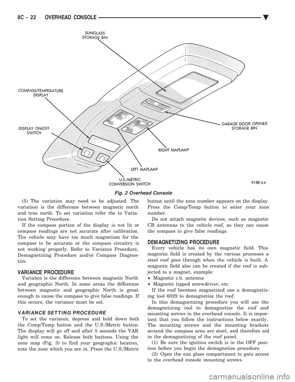
turns the compass display on and off. The US/Metric
switch changes the temperature reading from Fahr-
enheit to Celsius (Fig. 2). When the vehicle is standing still, engine compart-
ment temperatures may be radiated to the tempera-
ture sensor. Therefore the most accurate ambient
temperature readings are displayed when the vehicle
is moving in a forward motion. When the ignition switch is in the ON position the
temperature display is updated every 5 minutes.
When the ignition switch is turned off the last dis-
played temperature reading stays in memory. When
the ignition switch is turned on again the thermom-
eter will display the memory temperature for 1
minute; then update the display to the actual tem-
perature within 5 minutes.
COMPASS CALIBRATION
Do not attempt to set the compass near large metal
objects, such as, other vehicles, large buildings, or
bridges. The compass unit automatically calibrates itself as
the vehicle is driven; therefore, no calibration should
be required. When the compass is first powered up,
the CAL light on the display should be on. The CAL
light will go off and the compass will be accurate af-
ter the vehicle completes one to three complete cir-
cles. If the vehicle's compass headings are inaccurate,
the compass also can be manually calibrated using
the following procedures: (1) Depress and hold down both the Comp/Temp
button and the U.S./Metric button. (2) The display will go off and after 5 seconds the
VAR light will come on. Continue to hold both but-
tons down. (3) In approximately 10 seconds, the CAL light
will come on. Release both buttons and the display
will show the heading and outside temperature. (4) Drive the vehicle 1 to 3 complete circles, with-
out turning ignition OFF. The CAL light will then
go off, showing the compass is calibrated.
Fig. 1 Overhead Console Lamp Replacement
Ä OVERHEAD CONSOLE 8C - 21
Page 438 of 2438

(5) The variation may need to be adjusted. The
variation is the difference between magnetic north
and true north. To set variation refer the to Varia-
tion Setting Procedure. If the compass portion of the display is not lit or
compass readings are not accurate after calibration.
The vehicle may have too much magnetism for the
compass to be accurate or the compass circuitry is
not working properly. Refer to Variance Procedure,
Demagnetizing Procedure and/or Compass Diagnos-
tics.
VARIANCE PROCEDURE
Variance is the difference between magnetic North
and geographic North. In some areas the difference
between magnetic and geographic North is great
enough to cause the compass to give false readings. If
this occurs, the variance must be set.
VARIANCE SETTING PROCEDURE
To set the variance, depress and hold down both
the Comp/Temp button and the U.S./Metric button.
The display will go off and after 5 seconds the VAR
light will come on. Release both buttons. Using the
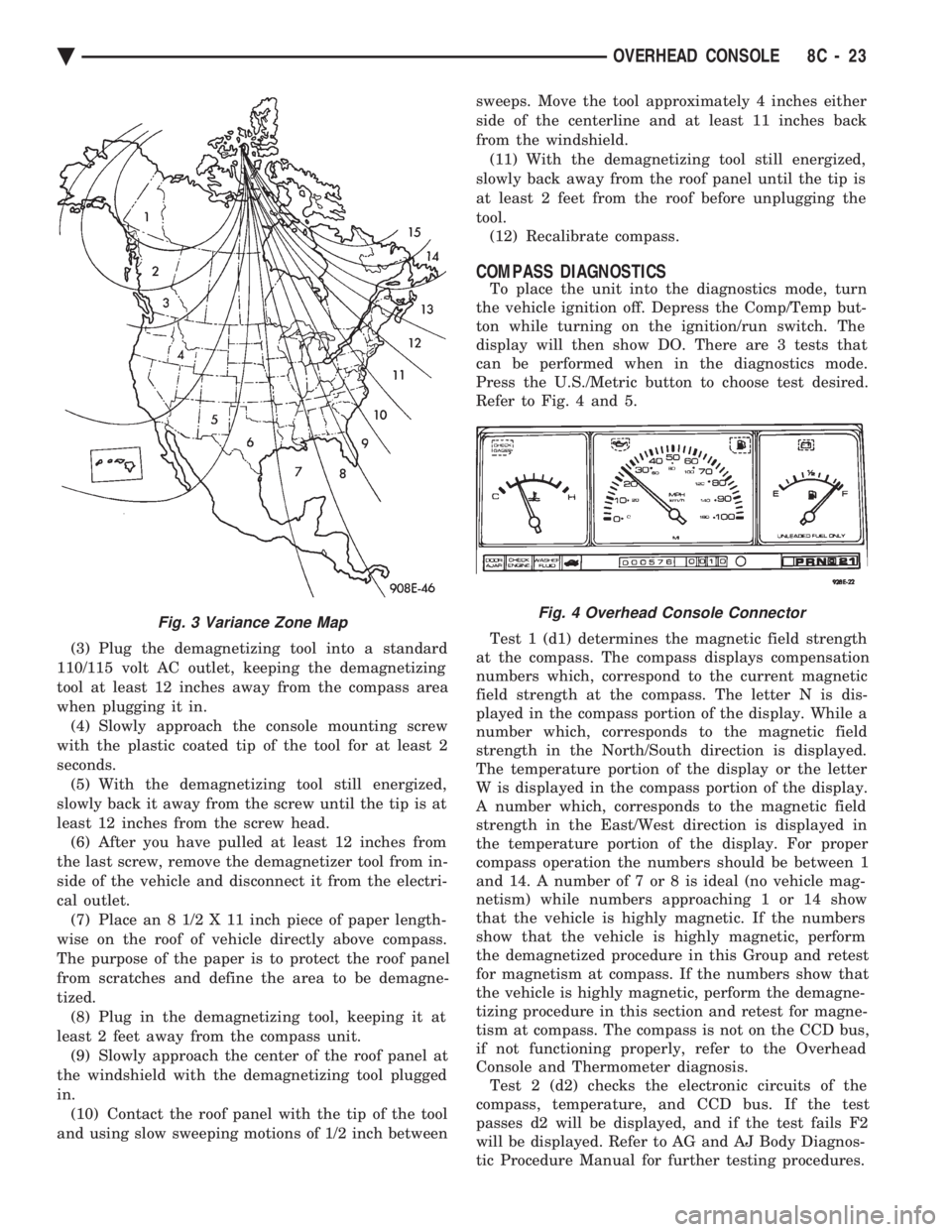
zone map (Fig. 3) to find your geographic location,
note the zone which you are in. Press the U.S./Metric button until the zone number appears on the display.
Press the Comp/Temp button to enter your zone
number. Do not attach magnetic devices, such as magnetic
CB antennas to the vehicle roof, as they can cause
the compass to give false readings.
DEMAGNETIZING PROCEDURE
Every vehicle has its own magnetic field. This
magnetic field is created by the various processes a
steel roof goes through when the vehicle is built. A
magnetic field also can be created if the roof is sub-
jected to a magnet, example:
² Magnetic c.b. antenna
² Magnetic tipped screwdriver, etc.
If the roof becomes magnetized use a demagnetiz-
ing tool 6029 to demagnetize the roof. In this demagnetizing procedure you will use the
demagnetizing tool to demagnetize the roof and
mounting screws in the overhead console. It is impor-
tant that you follow the instructions below exactly.
The mounting screws and the mounting brackets
around the compass area are steel, and therefore aid
in the demagnetizing of the roof panel. (1) Be sure the ignition switch is in the OFF posi-
tion before you begin the demagnetize procedure. (2) Open the sun glass compartment to gain access
to the overhead console mounting screws.
Fig. 2 Overhead Console
8C - 22 OVERHEAD CONSOLE Ä
Page 439 of 2438

(3) Plug the demagnetizing tool into a standard
110/115 volt AC outlet, keeping the demagnetizing
tool at least 12 inches away from the compass area
when plugging it in. (4) Slowly approach the console mounting screw
with the plastic coated tip of the tool for at least 2
seconds. (5) With the demagnetizing tool still energized,
slowly back it away from the screw until the tip is at
least 12 inches from the screw head. (6) After you have pulled at least 12 inches from
the last screw, remove the demagnetizer tool from in-
side of the vehicle and disconnect it from the electri-
cal outlet. (7) Place an 8 1/2 X 11 inch piece of paper length-
wise on the roof of vehicle directly above compass.
The purpose of the paper is to protect the roof panel
from scratches and define the area to be demagne-
tized. (8) Plug in the demagnetizing tool, keeping it at
least 2 feet away from the compass unit. (9) Slowly approach the center of the roof panel at
the windshield with the demagnetizing tool plugged
in. (10) Contact the roof panel with the tip of the tool
and using slow sweeping motions of 1/2 inch between sweeps. Move the tool approximately 4 inches either
side of the centerline and at least 11 inches back
from the windshield. (11) With the demagnetizing tool still energized,
slowly back away from the roof panel until the tip is
at least 2 feet from the roof before unplugging the
tool. (12) Recalibrate compass.
COMPASS DIAGNOSTICS
To place the unit into the diagnostics mode, turn
the vehicle ignition off. Depress the Comp/Temp but-
ton while turning on the ignition/run switch. The
display will then show DO. There are 3 tests that
can be performed when in the diagnostics mode.
Press the U.S./Metric button to choose test desired.
Refer to Fig. 4 and 5.
Test 1 (d1) determines the magnetic field strength
at the compass. The compass displays compensation
numbers which, correspond to the current magnetic
field strength at the compass. The letter N is dis-
played in the compass portion of the display. While a
number which, corresponds to the magnetic field
strength in the North/South direction is displayed.
The temperature portion of the display or the letter
W is displayed in the compass portion of the display.
A number which, corresponds to the magnetic field
strength in the East/West direction is displayed in
the temperature portion of the display. For proper
compass operation the numbers should be between 1
and 14. A number of 7 or 8 is ideal (no vehicle mag-
netism) while numbers approaching 1 or 14 show
that the vehicle is highly magnetic. If the numbers
show that the vehicle is highly magnetic, perform
the demagnetized procedure in this Group and retest
for magnetism at compass. If the numbers show that
the vehicle is highly magnetic, perform the demagne-
tizing procedure in this section and retest for magne-
tism at compass. The compass is not on the CCD bus,
if not functioning properly, refer to the Overhead
Console and Thermometer diagnosis. Test 2 (d2) checks the electronic circuits of the
compass, temperature, and CCD bus. If the test
passes d2 will be displayed, and if the test fails F2
will be displayed. Refer to AG and AJ Body Diagnos-
tic Procedure Manual for further testing procedures.
Fig. 3 Variance Zone MapFig. 4 Overhead Console Connector
Ä OVERHEAD CONSOLE 8C - 23
Page 441 of 2438

Test 3 (d3) performs a walking segment test which,
sequentially puts different directions and numbers on
the display. If any segment fails, replace the compass
module.
OVERHEAD CONSOLE REPLACEMENT
(1) Unscrew the mounting screw in sun glass bin
compartment (Fig. 6).
(2) Slide console forward toward windshield until
the console unhooks from roof bracket. (3) Disconnect wire harness from console.
(4) For installation reverse above procedures.
COMPASS MODULE REPLACEMENT
(1) Remove overhead console (Fig 6).
(2) Using a small screwdriver, release the 2 snaps
at rear of compass module (Fig. 7). (3) After releasing the 2 snaps, slide compass mod-
ule rearward until free of mounting bar. (4) For installation reverse above procedures.
AMBIENT TEMPERATURE SENSOR REMOVAL
(1) Raise and support vehicle on safety stands.
(2) Behind front bumper fascia, remove screw at-
taching sensor to radiator closure panel (Fig. 8). (3) For installation, reverse above procedures.
Fig. 6 Overhead Console Mounting
Fig. 7 Compass Module Removal
Fig. 8 Ambient Temperature Sensor
Ä
OVERHEAD CONSOLE 8C - 25
Page 445 of 2438

When testing secondary cables for punctures and
cracks with an oscilloscope follow the equipment
manufacturers instructions. If an oscilloscope is not available, secondary cables
can be tested as follows:
CAUTION: Do not leave any one spark plug cable
disconnected any longer than necessary during test-
ing. Excessive heat could damage the catalytic con-
verter. Total test time must not exceed ten minutes.
(a) With the engine not running, connect one end
of a test probe to a good ground. Use a probe made of
insulated wire with insulated alligator clips on each
end. (b) With engine running, move test probe along
entire length of all cables (approximately 0 to 1/8
inch gap). If punctures or cracks are present there
will be a noticeable spark jump from the faulty area
to the probe. Check the coil cable the same way.
Replace cracked, leaking or faulty cables.
When replacing cables, install the new high
tension cable and nipple assembly over cap or
coil tower. When entering the terminal into the
tower, push lightly, then pinch the large diam-
eter of nipple to release air trapped between the
nipple and tower. Continue pushing on the cable
and nipple until cables are properly seated in the
cap towers. A snap should be heard as terminal
goes into place. Use the same procedure to install cable in coil tower.
Wipe the spark plug insulator clean before reinstalling
cable and cover. Use the following procedure when removing the high
tension cable from the spark plug. First, remove the
cable from the retaining bracket. Then grasp the ter-
minal as close as possible to the spark plug. Rotate the
cover and pull the cable straight back. Pulling on the
cable itself will damage the conductor and termi-
nal connection. Do not use pliers and do not pull
the cable at an angle. Doing so will damage the
insulation, cable terminal or the spark plug in-
sulator. Wipe spark plug insulator clean before
reinstalling cable and cover. Resistance type cable is identified by the words
Electronic Suppression printed on the cable jacket.
Use an ohmmeter to check resistance type cable for
open circuits, loose terminals or high resistance as
follows: (a) Remove cable from spark plug.
(b) Lift distributor cap from distributor with
cables intact. Do not remove cables from cap. The
cables must be removed from the spark plugs. (c) Connect the ohmmeter between spark plug end
terminal and the corresponding electrode inside the
cap, make sure ohmmeter probes are in good contact.
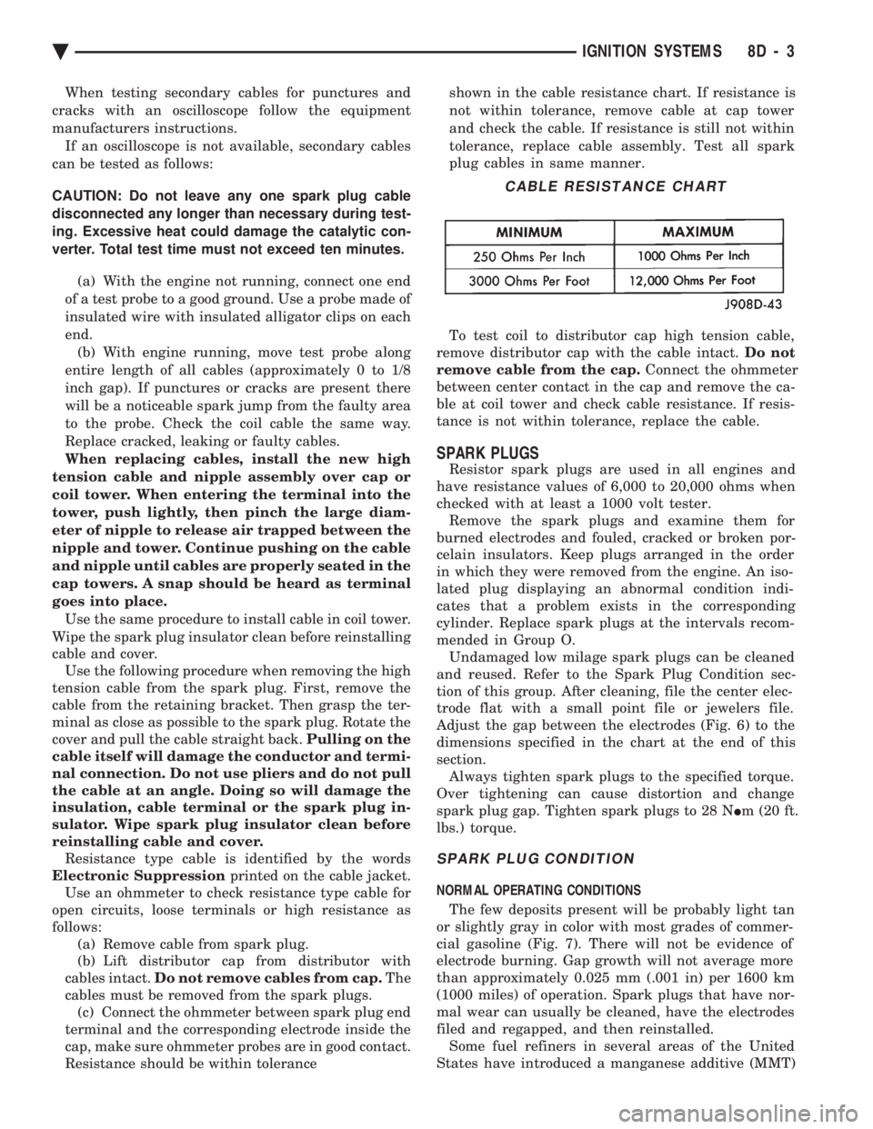
Resistance should be within tolerance shown in the cable resistance chart. If resistance is
not within tolerance, remove cable at cap tower
and check the cable. If resistance is still not within
tolerance, replace cable assembly. Test all spark
plug cables in same manner.
To test coil to distributor cap high tension cable,
remove distributor cap with the cable intact. Do not
remove cable from the cap. Connect the ohmmeter
between center contact in the cap and remove the ca-
ble at coil tower and check cable resistance. If resis-
tance is not within tolerance, replace the cable.
SPARK PLUGS
Resistor spark plugs are used in all engines and
have resistance values of 6,000 to 20,000 ohms when
checked with at least a 1000 volt tester. Remove the spark plugs and examine them for
burned electrodes and fouled, cracked or broken por-
celain insulators. Keep plugs arranged in the order
in which they were removed from the engine. An iso-
lated plug displaying an abnormal condition indi-
cates that a problem exists in the corresponding
cylinder. Replace spark plugs at the intervals recom-
mended in Group O. Undamaged low milage spark plugs can be cleaned
and reused. Refer to the Spark Plug Condition sec-
tion of this group. After cleaning, file the center elec-
trode flat with a small point file or jewelers file.
Adjust the gap between the electrodes (Fig. 6) to the
dimensions specified in the chart at the end of this
section. Always tighten spark plugs to the specified torque.
Over tightening can cause distortion and change
spark plug gap. Tighten spark plugs to 28 N Im (20 ft.
lbs.) torque.
SPARK PLUG CONDITION
NORMAL OPERATING CONDITIONS
The few deposits present will be probably light tan
or slightly gray in color with most grades of commer-
cial gasoline (Fig. 7). There will not be evidence of
electrode burning. Gap growth will not average more
than approximately 0.025 mm (.001 in) per 1600 km
(1000 miles) of operation. Spark plugs that have nor-
mal wear can usually be cleaned, have the electrodes
filed and regapped, and then reinstalled. Some fuel refiners in several areas of the United
States have introduced a manganese additive (MMT)
CABLE RESISTANCE CHART
Ä IGNITION SYSTEMS 8D - 3
Page 468 of 2438

tance. The cables provide suppression of radio fre-
quency emissions from the ignition system.Check the spark plug cable connections for good
contact at the coil and distributor cap towers and at
the spark plugs. Terminals should be fully seated.
The nipples and spark plug covers should be in good
condition. Nipples should fit tightly on the coil and
distributor cap towers and spark plug cover should
fit tight around spark plug insulators. Loose cable
connections can cause ignition malfunctions by per-
mitting water to enter the towers, corroding, and in-
creasing resistance.
SPARK PLUGS
The 2.2L Turbo III, 3.3L and 3.8L engines use re-
sistor spark plugs. They have resistance values of
6,000 to 20,000 ohms when checked with at least a
1000 volt tester. Remove the spark plugs and examine them for
burned electrodes and fouled, cracked or broken por-
celain insulators. Keep plugs arranged in the order
in which they were removed from the engine. An iso-
lated plug displaying an abnormal condition indi-
cates that a problem exists in the corresponding
cylinder. Replace spark plugs at the intervals recom-
mended in Group O. Spark plugs that have low milage may be cleaned
and reused if not otherwise defective. Refer to the
Spark Plug Condition section of this group. After
cleaning, file the center electrode flat with a small
point file or jewelers file. Adjust the gap between the
electrodes (Fig. 8) to the dimensions specified in the
chart at the end of this section.
Always tighten spark plugs to the specified torque.
Over tightening can cause distortion and change
spark plug gap. Tighten 2.2L Turbo III, 3.3L and
3.8L spark plugs to 28 N Im (20 ft. lbs.) torque.
SPARK PLUG CONDITION
NORMAL OPERATING CONDITIONS
The few deposits present will be probably light tan
or slightly gray in color with most grades of commer-
cial gasoline (Fig. 9). There will not be evidence of
electrode burning. Gap growth will not average more
than approximately 0.025 mm (.001 in) per 1600 km
(1000 miles) of operation. Spark plugs that have nor-
Fig. 6 Spark Plug Wire RoutingÐ3.3L and 3.8L Engines
Fig. 7 Powertrain Control Module (PCM)
Fig. 8 Setting Spark Plug Electrode GapÐTypical
8D - 26 IGNITION SYSTEMS Ä
Page 471 of 2438

tion (Fig. 16 or Fig. 17). The sensor generates pulses
that are the input sent to the PCM. The PCM inter-
prets the camshaft position sensor input (along with
the crankshaft position sensor input) to determine
crankshaft position. The PCM uses the crankshaft
position sensor input to determine injector sequence
and ignition timing.
The camshaft position sensor determines when a slot
in the camshaft gear passes beneath it (Fig. 18 or Fig.
19). When metal aligns with the sensor, voltage goes
low (less than 0.5 volts). When a notch aligns with the
sensor, voltage spikes high (5.0 volts). As a group of
notches pass under the sensor, the voltage switches
from low (metal) to high (notch) then back to low. The
number of notches determine the amount of pulses. If
available, an oscilloscope can display the square wave
patterns of each timing events. The camshaft position sensor is mounted to the top
of the timing case cover (Fig. 20 or Fig. 21). The bot-
tom of the sensor is positioned above the camshaft
sprocket. The distance between the bottom of
sensor and the camshaft sprocket is critical to
the operation of the system. When servicing the
camshaft position sensor, refer to the Turbo III, 3.3L and 3.8L Ignition SystemÐService Proce-
dures section in this Group.
CRANKSHAFT POSITION SENSOR
The crankshaft position sensor senses slots cut into
the transaxle driveplate extension (Fig. 22 or Fig. 23).
On Turbo III, there ar e a 2 sets of slots. Each set
contains 4 slots, for a total of 8 slots (Fig. 24). On 3.3L
and 3.8L engines, there ar e a 3 sets of slots. Each set
contains 4 slots, for a total of 12 slots (Fig. 25).
Fig. 16 Camshaft Position SensorÐTurbo III Engine
Fig. 17 Camshaft Position SensorÐ3.3L and 3.8L Engines
Fig. 18 Camshaft GearÐTurbo III Engine
Fig. 19 Camshaft GearÐ3.3L and 3.8L Engines
Ä IGNITION SYSTEMS 8D - 29
Page 493 of 2438

INSTRUMENT PANEL AND GAUGES
CONTENTS
page page
AA BODY .............................. 1
AC AND AY BODIES .................... 23 AG AND AJ BODIES
.................... 42
AP BODY ............................. 58
AA BODY INDEX
page page
Cluster and Gauge Service and Testing ........ 2
Electronic Cluster ........................ 13
Fuel GaugeÐFlexible Fuel .................. 2
Gauges ................................. 7
General Information ........................ 1 Instrument Panel
......................... 21
Interior Lamp Replacement ................. 21
Mechanical/Electronic Cluster Removal ......... 5
Switch and Panel Component Service ......... 15
GENERAL INFORMATION
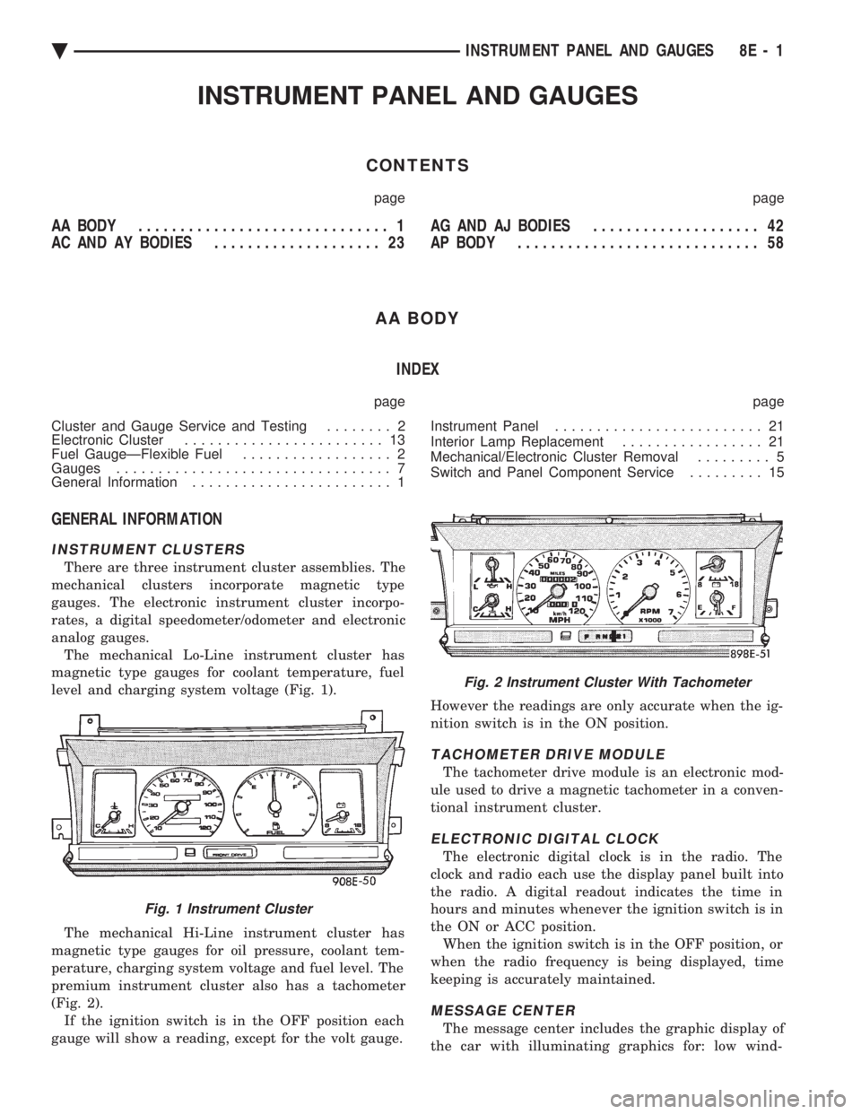
INSTRUMENT CLUSTERS
There are three instrument cluster assemblies. The
mechanical clusters incorporate magnetic type
gauges. The electronic instrument cluster incorpo-
rates, a digital speedometer/odometer and electronic
analog gauges. The mechanical Lo-Line instrument cluster has
magnetic type gauges for coolant temperature, fuel
level and charging system voltage (Fig. 1).
The mechanical Hi-Line instrument cluster has
magnetic type gauges for oil pressure, coolant tem-
perature, charging system voltage and fuel level. The
premium instrument cluster also has a tachometer
(Fig. 2). If the ignition switch is in the OFF position each
gauge will show a reading, except for the volt gauge. However the readings are only accurate when the ig-
nition switch is in the ON position.
TACHOMETER DRIVE MODULE
The tachometer drive module is an electronic mod-
ule used to drive a magnetic tachometer in a conven-
tional instrument cluster.
ELECTRONIC DIGITAL CLOCK
The electronic digital clock is in the radio. The
clock and radio each use the display panel built into
the radio. A digital readout indicates the time in
hours and minutes whenever the ignition switch is in
the ON or ACC position. When the ignition switch is in the OFF position, or
when the radio frequency is being displayed, time
keeping is accurately maintained.
MESSAGE CENTER
The message center includes the graphic display of
the car with illuminating graphics for: low wind-
Fig. 1 Instrument Cluster
Fig. 2 Instrument Cluster With Tachometer
Ä INSTRUMENT PANEL AND GAUGES 8E - 1