1993 CHEVROLET PLYMOUTH ACCLAIM ad blue
[x] Cancel search: ad bluePage 2064 of 2438

(7) Press the number 5 on the DRB II scan tool
key pad (Adjustments). (8) Press the number 3 on the DRB II scan tool
key pad (Quick Learn). Then follow the instructions
on the DRB II scan tool screen.
PINION FACTOR PROCEDURE
The vehicle speed readings for the speedometer are
taken from the output speed sensor. Because of dif-
ferent tire sizes and final drive ratios, the transmis-
sion control module must be calibrated to reflect the
different combinations of equipment. A procedure has
been developed called Pinion Factor. It allows the
technician to set the transmission control module ini-
tial setting so that the speedometer readings will be
correct. Failure to perform this procedure will cause a ``No
Speedometer Operation'' condition. This procedure must be performed if the transmis-
sion control module has been replaced. To properly read or reset the Pinion Factor, it is
necessary to use a DRB II scan tool. Perform the fol-
lowing steps with the DRB II scan tool to read or re-
set the Pinion Factor: (1) Plug the DRB II scan tool into the blue CCD
Bus connector. The connector is located under the in-
strument panel on the drivers side of the vehicle. (2) Insert the 1993 DRB II scan tool cartridge into
the DRB II scan tool. (3) The red and green lights on the DRB II scan
tool will light up and then begin flashing. Wait until
the lights stop flashing before continuing with this
procedure. (4) Press the number 4 key (Select System) on the
DRB II scan tool key pad. Item number 4 will not ap-
pear on the DRB II scan tool screen unless you scroll
down. It is not necessary to scroll down to be able to
choose item 4. (5) Press the number 2 on the DRB II scan tool
key pad (Transmission). (6) Press the number 1 on the DRB II scan tool
key pad. Wait for the DRB II scan tool to perform the
following three tests before continuing (These tests
are done automatically by the DRB II scan tool).
² Bus Test
² Initialize
² Transmission Control Module Part Number
(7) Press the number 5 on the DRB II scan tool
key pad (Adjustments). (8) Press the number 2 on the DRB II scan tool
key pad (Pinion Factor). Then follow the instructions
on the DRB II scan tool screen.
TORQUE CONVERTER CLUTCH BREAK-IN
PROCEDURE
A torque converter clutch break-in program is be-
ing used on all models with a 41TE. This program
will properly condition the torque converter clutch. This will eliminate shudder during partial torque
converter clutch operation on a new torque converter.
If the torque converter is replaced, the new clutch
within the torque converter will require break-in.
The current break-in status stored in the transmis-
sion control module will have to be reset to the start
of break-in with the DRB II scan tool. If a new transmission control module is put on the
vehicle, the status will be at the start of break-in.
This status is acceptable regardless of the mileage on
the torque converter. No modification of the break-in
status is required. To properly service these vehicles, it is necessary to
use a DRB II scan tool to read or reset the break-in
status. Perform the following steps with the DRB II
scan tool to reset the break-in status: (1) Plug the DRB II scan tool into the blue CCD
Bus connector. The connector is located under the in-
strument panel on the drivers side of the vehicle. (2) Insert the 1993 DRB II scan tool cartridge into
the DRB II scan tool. (3) The red and green lights on the DRB II scan
tool will light up and then begin flashing. Wait until
the lights stop flashing before continuing with this
procedure. (4) Press the number 4 key (Select System) on the
DRB II scan tool key pad. Item number 4 will not ap-
pear on the DRB II scan tool screen unless you scroll
down. It is not necessary to scroll down to be able to
choose item 4. (5) Press the number 2 on the DRB II scan tool
key pad (Transmission). (6) Press the number 1 on the DRB II scan tool
key pad. Wait for the DRB II scan tool to perform the
following three tests before continuing (These tests
are done automatically by the DRB II scan tool).
² Bus Test
² Initialize
² Transmission Control Module Part Number
(7) Press the number 5 on the DRB II scan tool
key pad (Adjustments). (8) Press the number 1 on the DRB II scan tool
key pad (Reset LU Clutch). The DRB II scan tool will
display one of three screens. (a) LU Clutch Break-in Status: Start
(b) LU Clutch Break-in Status: In-progress
Press ENTER to Reset Break-in status (c) LU Clutch Break-in Status: CompletePress
ENTER to Reset Break-in status
If screen (a) appears, the transmission control mod-
ule is at the beginning of its break-in program. No
further action is required. If screen (b) appears, the transmission control mod-
ule is in the middle of a its break-in program. Press
the enter key on the DRB II scan tool key pad to re-
turn the status to the start of break-in.
21 - 104 TRANSAXLE Ä
Page 2065 of 2438

If screen (c) appears, the transmission control mod-
ule has completed its break-in status program. Press
the enter key on the DRB II scan tool key pad to return
the status to the start of break-in. (9) After pressing the enter key a second time in step
8 a screen will appear that says ``RESET LU CLUTCH
ARE YOU SURE ?''. Press the enter key on the DRB II
scan tool key pad. The DRB II scan tool will then carry
out the reset command. (10) After the DRB II scan tool completes the reset
command, a screen will appear saying ``LU Clutch
Break-in Status has been RESET to Start''. This screen
will indicate that the reset procedure has been success-
fully completed. (11) Disconnect the DRB II scan tool from the blue
CCD Bus connector.
TRANSAXLE RECONDITION
Tag all clutch pack assemblies, as they are
removed, for reassembly identification.
CAUTION: Do not intermix clutch discs or plates as
the unit might then fail.
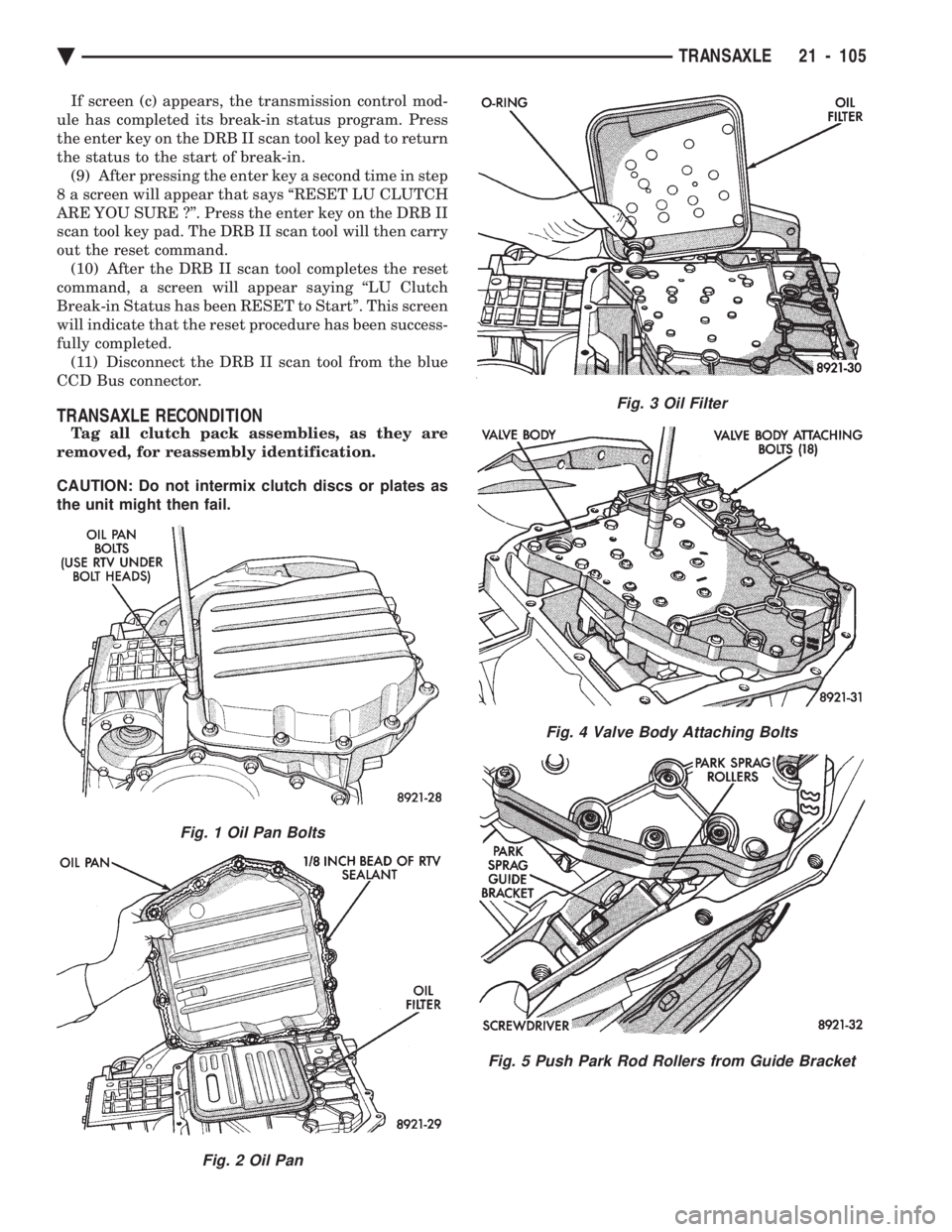
Fig. 1 Oil Pan Bolts
Fig. 2 Oil Pan
Fig. 3 Oil Filter
Fig. 4 Valve Body Attaching Bolts
Fig. 5 Push Park Rod Rollers from Guide Bracket
Ä TRANSAXLE 21 - 105
Page 2106 of 2438

² Park
² Neutral
² Reverse
² Second Gear
No upshifts or downshifts are allowed while in the
Limp-in mode. The position of the manual valve
alone allows the three ranges that are available. Although engine performance will be reduced while
in this mode, the vehicle can be driven in for service.
DRB II SCAN TOOL
The DRB II scan tool is a diagnostic read-out box
designed by Chrysler to gain access to the on-board
diagnostics. These on-board diagnostics are found on
all Chrysler-built cars and trucks. The DRB II scan tool has a few diagnostic capabil-
ities by itself. To perform most diagnostic tests, a
program cartridge must be inserted. It contains the
diagnostic test programs. There are scan tools available from other manufac-
tures that can be used on Chrysler vehicles. How-
ever, the diagnostic test procedures in this manual
have been designed for use with the Chrysler's DRB
II scan tool. The DRB II scan tool operates by communicating
with the module of the vehicle system being tested.
To communicate with the transmission control mod-
ule, the DRB II scan tool must be connected to the blue CCD bus connector located under the instru-
ment panel. Refer to the ``Using the DRB II Scan
Tool'' manual or the Diagnostic Procedures Manual
for information on how to use the DRB II scan tool.
DIAGNOSTIC TROUBLE CODE CHARTS
Below is a brief description of what each section of
the diagnostic trouble code charts are addressing.
² DIAGNOSTIC TROUBLE CODE- Tells the code
number and name (as shown on the DRB II scan
tool).
² BACKGROUND- A brief description of the circuit
that the transmission control module is monitoring.
² WHEN CHECKED- The point of time or condition
when the transmission control module makes it's sys-
tem check.
² ARMING CONDITIONS- The parameters that
must be met before a code can be set.
² FAULT CONDITION- What the transmission con-
trol module saw that is determined to be a problem.
(ie. voltage to high or low, switch/solenoid problems)
² FAULT SET TIME- Refers to the amount of time
(in seconds) a failure must occur before a diagnostic
trouble code is set in memory.
² EFFECT- Refers to how the fault effects transaxle
operations.
² POSSIBLE CAUSE- Refers to the systems or cir-
cuits which could cause the fault to be recorded.
21 - 146 TRANSAXLE Ä
Page 2313 of 2438

REFRIGERANT RECYCLING
(R-12) refrigerant is a chlorofluorocarbon (CFC)
that can contribute to the depletion of the ozone
layer in the upper atmosphere. To help protect the
ozone layer, an R-12 recycling device must be used.
Contact an automotive service equipment supplier
for refrigerant recycling equipment. Refer to the op-
erating instructions provided with the recycling
equipment for proper operation.
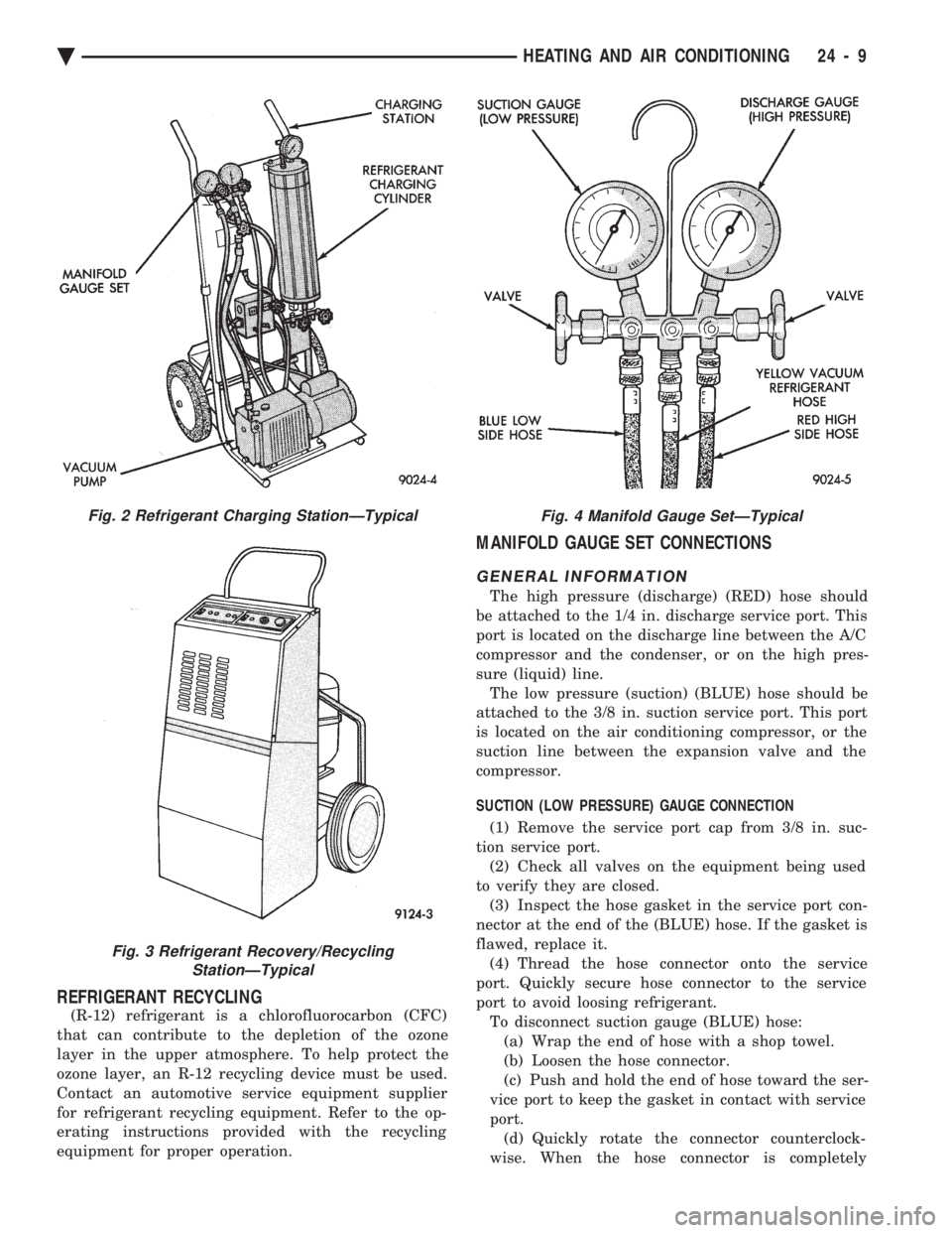
MANIFOLD GAUGE SET CONNECTIONS
GENERAL INFORMATION
The high pressure (discharge) (RED) hose should
be attached to the 1/4 in. discharge service port. This
port is located on the discharge line between the A/C
compressor and the condenser, or on the high pres-
sure (liquid) line. The low pressure (suction) (BLUE) hose should be
attached to the 3/8 in. suction service port. This port
is located on the air conditioning compressor, or the
suction line between the expansion valve and the
compressor.
SUCTION (LOW PRESSURE) GAUGE CONNECTION
(1) Remove the service port cap from 3/8 in. suc-
tion service port. (2) Check all valves on the equipment being used
to verify they are closed. (3) Inspect the hose gasket in the service port con-
nector at the end of the (BLUE) hose. If the gasket is
flawed, replace it. (4) Thread the hose connector onto the service
port. Quickly secure hose connector to the service
port to avoid loosing refrigerant. To disconnect suction gauge (BLUE) hose:(a) Wrap the end of hose with a shop towel.
(b) Loosen the hose connector.
(c) Push and hold the end of hose toward the ser-
vice port to keep the gasket in contact with service
port. (d) Quickly rotate the connector counterclock-
wise. When the hose connector is completely
Fig. 2 Refrigerant Charging StationÐTypical
Fig. 3 Refrigerant Recovery/Recycling StationÐTypical
Fig. 4 Manifold Gauge SetÐTypical
Ä HEATING AND AIR CONDITIONING 24 - 9