1993 CHEVROLET PLYMOUTH ACCLAIM check engine
[x] Cancel search: check enginePage 1820 of 2438
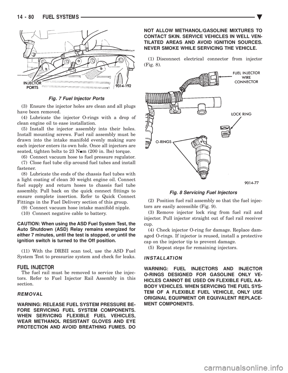
(3) Ensure the injector holes are clean and all plugs
have been removed. (4) Lubricate the injector O-rings with a drop of
clean engine oil to ease installation. (5) Install the injector assembly into their holes.
Install mounting screws. Fuel rail assembly must be
drawn into the intake manifold evenly making sure
each injector enters its own hole. Once all injectors are
seated, tighten bolts to 23 N Im (200 in. lbs) torque.
(6) Connect vacuum hose to fuel pressure regulator.
(7) Close fuel tube clip around fuel tubes and install
fastener. (8) Lubricate the ends of the chassis fuel tubes with
a light coating of clean 30 weight engine oil. Connect
fuel supply and return hoses to chassis fuel tube
assembly. Pull back on the quick connect fittings to
ensure complete insertion. Refer to Quick Connect
Fittings in the Fuel Delivery section of this group. (9) Connect vacuum hose intake manifold nipple.
(10) Connect negative cable to battery.
CAUTION: When using the ASD Fuel System Test, the
Auto Shutdown (ASD) Relay remains energized for
either 7 minutes, until the test is stopped, or until the
ignition switch is turned to the Off position.
(11) With the DRBII scan tool, use the ASD Fuel
System Test to pressurize system and check for leaks.
FUEL INJECTOR
The fuel rail must be removed to service the injec-
tors. Refer to Fuel Injector Rail Assembly in this
section.
REMOVAL
WARNING: RELEASE FUEL SYSTEM PRESSURE BE-
FORE SERVICING FUEL SYSTEM COMPONENTS.
WHEN SERVICING FLEXIBLE FUEL VEHICLES,
WEAR METHANOL RESISTANT GLOVES AND EYE
PROTECTION AND AVOID BREATHING FUMES. DO NOT ALLOW METHANOL/GASOLINE MIXTURES TO
CONTACT SKIN. SERVICE VEHICLES IN WELL VEN-
TILATED AREAS AND AVOID IGNITION SOURCES.
NEVER SMOKE WHILE SERVICING THE VEHICLE.
(1) Disconnect electrical connector from injector
(Fig. 8).
(2) Position fuel rail assembly so that the fuel injec-
tors are easily accessible (Fig. 9). (3) Remove injector lock ring from fuel rail and
injector. Pull injector straight out of fuel rail receiver
cup. (4) Check injector O-ring for damage. Replace dam-
aged O-rings. If injector is reused, install a protective
cap on the injector tip to prevent damage. (5) Repeat steps for remaining injectors.
INSTALLATION
WARNING: FUEL INJECTORS AND INJECTOR
O-RINGS DESIGNED FOR GASOLINE ONLY VE-
HICLES CANNOT BE USED ON FLEXIBLE FUEL AA-
BODY VEHICLES. WHEN SERVICING THE FUEL SYS-
TEM OF A FLEXIBLE FUEL VEHICLE, ONLY USE
ORIGINAL EQUIPMENT OR EQUIVALENT REPLACE-
MENT COMPONENTS.
Fig. 7 Fuel Injector Ports
Fig. 8 Servicing Fuel Injectors
14 - 80 FUEL SYSTEMS Ä
Page 1823 of 2438
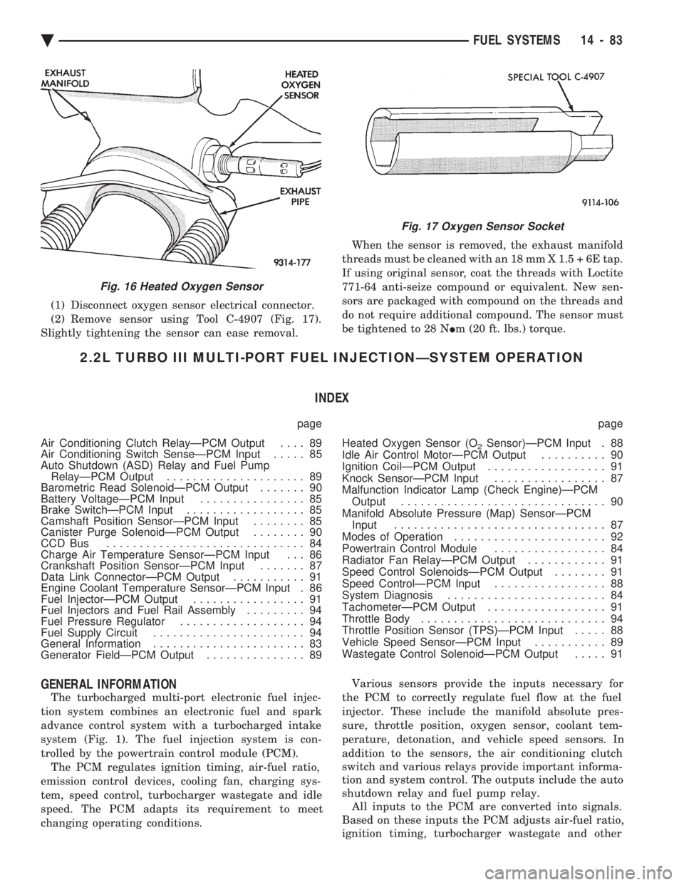
(1) Disconnect oxygen sensor electrical connector.
(2) Remove sensor using Tool C-4907 (Fig. 17).
Slightly tightening the sensor can ease removal. When the sensor is removed, the exhaust manifold
threads must be cleaned with an 18 mm X 1.5 + 6E tap.
If using original sensor, coat the threads with Loctite
771-64 anti-seize compound or equivalent. New sen-
sors are packaged with compound on the threads and
do not require additional compound. The sensor must
be tightened to 28 N Im (20 ft. lbs.) torque.
2.2L TURBO III MULTI-PORT FUEL INJECTIONÐSYSTEM OPERATION
INDEX
page page
Air Conditioning Clutch RelayÐPCM Output .... 89
Air Conditioning Switch SenseÐPCM Input ..... 85
Auto Shutdown (ASD) Relay and Fuel Pump RelayÐPCM Output ..................... 89
Barometric Read SolenoidÐPCM Output ....... 90
Battery VoltageÐPCM Input ................ 85
Brake SwitchÐPCM Input .................. 85
Camshaft Position SensorÐPCM Input ........ 85
Canister Purge SolenoidÐPCM Output ........ 90
CCD Bus .............................. 84
Charge Air Temperature SensorÐPCM Input . . . 86
Crankshaft Position SensorÐPCM Input ....... 87
Data Link ConnectorÐPCM Output ........... 91
Engine Coolant Temperature SensorÐPCM Input . 86
Fuel InjectorÐPCM Output ................. 91
Fuel Injectors and Fuel Rail Assembly ......... 94
Fuel Pressure Regulator ................... 94
Fuel Supply Circuit ....................... 94
General Information ....................... 83
Generator FieldÐPCM Output ............... 89 Heated Oxygen Sensor (O
2Sensor)ÐPCM Input . 88
Idle Air Control MotorÐPCM Output .......... 90
Ignition CoilÐPCM Output .................. 91
Knock SensorÐPCM Input ................. 87
Malfunction Indicator Lamp (Check Engine)ÐPCM Output ............................... 90
Manifold Absolute Pressure (Map) SensorÐPCM Input ................................ 87
Modes of Operation ....................... 92
Powertrain Control Module ................. 84
Radiator Fan RelayÐPCM Output ............ 91
Speed Control SolenoidsÐPCM Output ........ 91
Speed ControlÐPCM Input ................. 88
System Diagnosis ........................ 84
TachometerÐPCM Output .................. 91
Throttle Body ............................ 94
Throttle Position Sensor (TPS)ÐPCM Input ..... 88
Vehicle Speed SensorÐPCM Input ........... 89
Wastegate Control SolenoidÐPCM Output ..... 91
GENERAL INFORMATION
The turbocharged multi-port electronic fuel injec-
tion system combines an electronic fuel and spark
advance control system with a turbocharged intake
system (Fig. 1). The fuel injection system is con-
trolled by the powertrain control module (PCM). The PCM regulates ignition timing, air-fuel ratio,
emission control devices, cooling fan, charging sys-
tem, speed control, turbocharger wastegate and idle
speed. The PCM adapts its requirement to meet
changing operating conditions. Various sensors provide the inputs necessary for
the PCM to correctly regulate fuel flow at the fuel
injector. These include the manifold absolute pres-
sure, throttle position, oxygen sensor, coolant tem-
perature, detonation, and vehicle speed sensors. In
addition to the sensors, the air conditioning clutch
switch and various relays provide important informa-
tion and system control. The outputs include the auto
shutdown relay and fuel pump relay. All inputs to the PCM are converted into signals.
Based on these inputs the PCM adjusts air-fuel ratio,
ignition timing, turbocharger wastegate and other
Fig. 16 Heated Oxygen Sensor
Fig. 17 Oxygen Sensor Socket
Ä FUEL SYSTEMS 14 - 83
Page 1824 of 2438
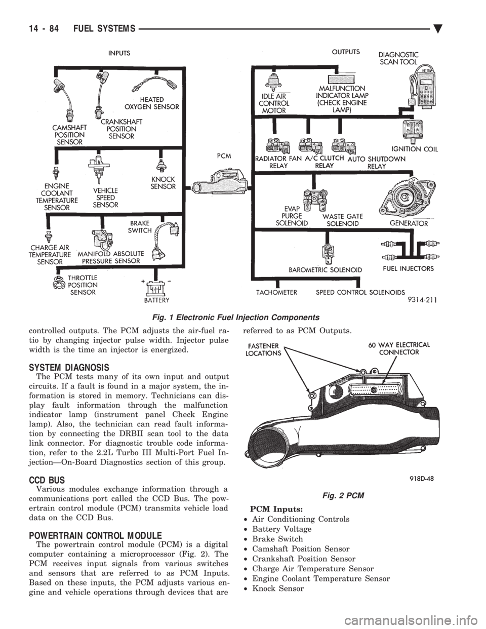
controlled outputs. The PCM adjusts the air-fuel ra-
tio by changing injector pulse width. Injector pulse
width is the time an injector is energized.
SYSTEM DIAGNOSIS
The PCM tests many of its own input and output
circuits. If a fault is found in a major system, the in-
formation is stored in memory. Technicians can dis-
play fault information through the malfunction
indicator lamp (instrument panel Check Engine
lamp). Also, the technician can read fault informa-
tion by connecting the DRBII scan tool to the data
link connector. For diagnostic trouble code informa-
tion, refer to the 2.2L Turbo III Multi-Port Fuel In-
jectionÐOn-Board Diagnostics section of this group.
CCD BUS
Various modules exchange information through a
communications port called the CCD Bus. The pow-
ertrain control module (PCM) transmits vehicle load
data on the CCD Bus.
POWERTRAIN CONTROL MODULE
The powertrain control module (PCM) is a digital
computer containing a microprocessor (Fig. 2). The
PCM receives input signals from various switches
and sensors that are referred to as PCM Inputs.
Based on these inputs, the PCM adjusts various en-
gine and vehicle operations through devices that are referred to as PCM Outputs.
PCM Inputs:
² Air Conditioning Controls
² Battery Voltage
² Brake Switch
² Camshaft Position Sensor
² Crankshaft Position Sensor
² Charge Air Temperature Sensor
² Engine Coolant Temperature Sensor
² Knock Sensor
Fig. 1 Electronic Fuel Injection Components
Fig. 2 PCM
14 - 84 FUEL SYSTEMS Ä
Page 1825 of 2438
² Manifold Absolute Pressure (MAP) Sensor
² Oxygen Sensor
² SCI Receive
² Speed Control System Controls
² Throttle Position Sensor
² Vehicle Speed Sensor
PCM Outputs:
² Air Conditioning Clutch Relay
² Generator Field
² Idle Air Control Motor
² Auto Shutdown (ASD) Relay
² Barometric Read Solenoid
² Canister Purge Solenoid
² Malfunction Indicator Lamp (Check Engine Lamp)
² Data Link Connector
² Fuel Injectors
² Ignition Coil
² Radiator Fan Relay
² Speed Control Solenoids
² Tachometer Output
² Wastegate Solenoid
Based on inputs it receives, the PCM adjusts fuel
injector pulse width, idle speed, ignition spark ad-
vance, ignition coil dwell and canister purge opera-
tion. The PCM regulates operation of the cooling fan,
A/C and speed control systems. The PCM changes
generator charge rate by adjusting the generator
field. The PCM adjusts injector pulse width (air-fuel ra-
tio) based on the following inputs.
² battery voltage
² engine coolant temperature
² exhaust gas content
² engine speed (crankshaft position sensor)
² manifold absolute pressure
² throttle position
The PCM adjusts ignition timing based on the fol-
lowing inputs.
² engine coolant temperature
² knock sensor
² engine speed (crankshaft position sensor)
² manifold absolute pressure
² throttle position
The Automatic Shut Down (ASD) and Fuel Pump
relays are mounted externally, but turned on and off
by the PCM through the same circuit. The camshaft position sensor and crankshaft posi-
tion sensor signals are sent to the PCM. If the PCM
does not receive both signals within approximately
one second of engine cranking, it deactivates the
ASD relay and fuel pump relay. When these relays
are deactivated, power is shut off to the fuel injector,
ignition coil, oxygen sensor heating element and fuel
pump. The PCM contains a voltage converter that
changes battery voltage to a regulated 8.0 volts. The
8.0 volts power the camshaft position sensor, crank- shaft position sensor and vehicle speed sensor. The
PCM also provides a 5.0 volts supply for the coolant
temperature sensor, manifold absolute pressure sen-
sor and throttle position sensor.
AIR CONDITIONING SWITCH SENSEÐPCM INPUT
When the air conditioning or defrost switch is put
in the ON position and the low pressure and high
pressure switches are closed, the PCM receives an in-
put for air conditioning. After receiving this input,
the PCM activates the A/C compressor clutch by
grounding the A/C clutch relay. The PCM also ad-
justs idle speed to a scheduled RPM to compensate
for increased engine load.
BATTERY VOLTAGEÐPCM INPUT
The PCM monitors the battery voltage input to de-
termine fuel injector pulse width and generator field
control. If battery voltage is low the PCM will in-
crease injector pulse width (period of time that the
injector is energized).
BRAKE SWITCHÐPCM INPUT
When the brake switch is activated, the PCM re-
ceives an input indicating that the brakes are being
applied. After receiving this input, the PCM vents
the speed control servo. Venting the servo turns the
speed control system off. The brake switch is
mounted on the brake pedal support bracket.
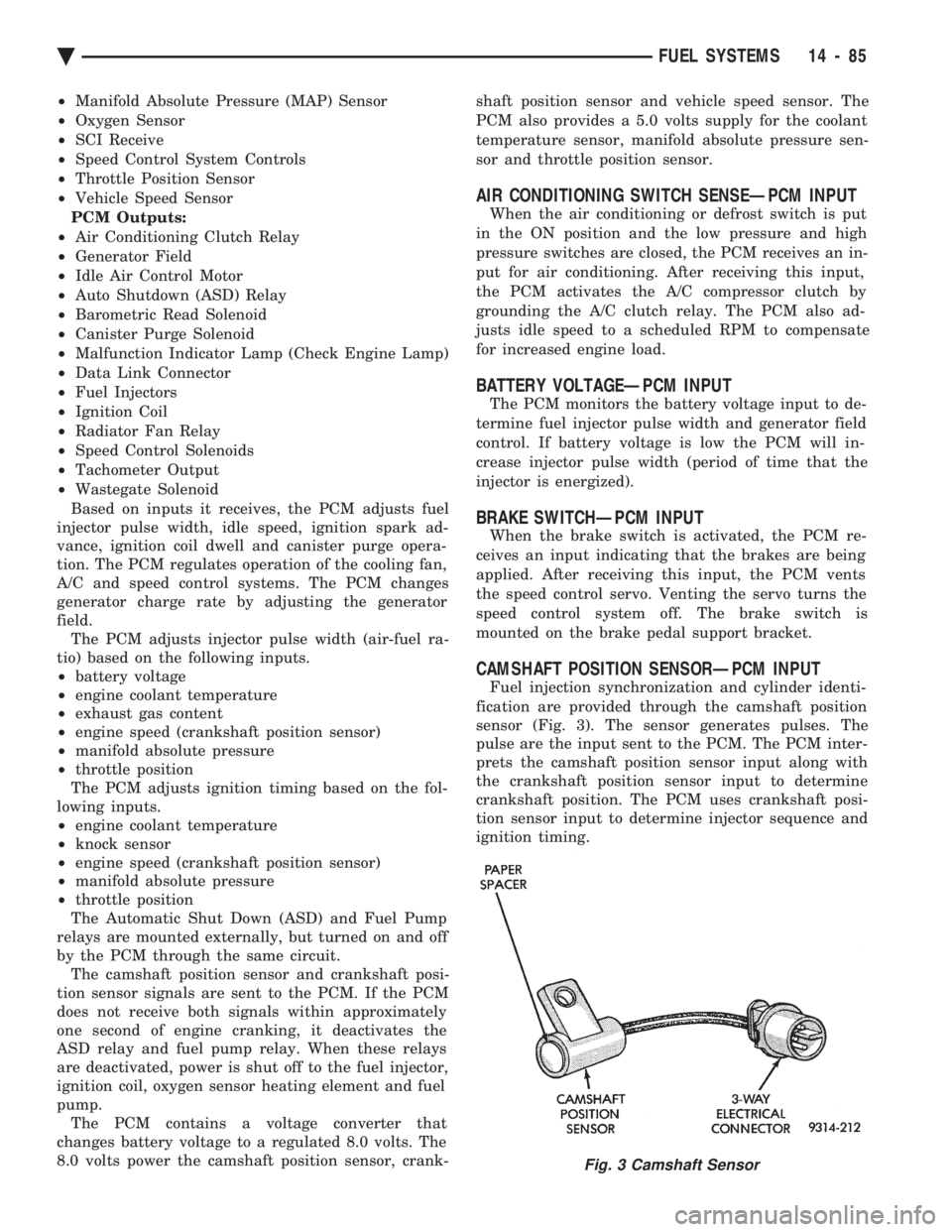
CAMSHAFT POSITION SENSORÐPCM INPUT
Fuel injection synchronization and cylinder identi-
fication are provided through the camshaft position
sensor (Fig. 3). The sensor generates pulses. The
pulse are the input sent to the PCM. The PCM inter-
prets the camshaft position sensor input along with
the crankshaft position sensor input to determine
crankshaft position. The PCM uses crankshaft posi-
tion sensor input to determine injector sequence and
ignition timing.
Fig. 3 Camshaft Sensor
Ä FUEL SYSTEMS 14 - 85
Page 1830 of 2438
sition, the PCM monitors the crankshaft position and
camshaft position sensor signals to determine engine
speed and ignition timing (coil dwell). If the PCM
does not receive the crankshaft position sensor and
camshaft position sensor signals when the ignition
switch is in the Run position, it de-energizes both re-
lays. When the relays are de-energized, battery volt-
age is not supplied to the fuel injector, ignition coil,
fuel pump and oxygen sensor heating element. The ASD relay and fuel pump relay are located in
the power distribution center (Fig. 16).
IDLE AIR CONTROL MOTORÐPCM OUTPUT
The idle air control motor is mounted on the throt-
tle body (Fig. 14). The PCM operates the motor. The
PCM adjusts engine idle speed through the idle air
control motor to compensate for engine load or ambi-
ent conditions. The throttle body has an air bypass passage that
provides air for the engine at idle (the throttle blade
is closed). The idle air control motor pintle protrudes
into the air bypass passage and regulates air flow
through it. The PCM adjusts engine idle speed by moving the
idle air control motor pintle in and out of the bypass
passage. The adjustments are based on inputs the
PCM receives. The inputs are from the throttle posi-
tion sensor, camshaft position sensor, crankshaft po-
sition sensor, coolant temperature sensor, and
various switch operations (brake and air condition-
ing). Deceleration die out is also prevented by in-
creasing airflow when the throttle is closed quickly
after a driving (speed) condition.
BAROMETRIC READ SOLENOIDÐPCM OUTPUT
The barometric pressure read solenoid is spliced
into the manifold absolute pressure (MAP) sensor
vacuum hose (Fig. 12). The barometric read solenoid
switches the pressure supply to the MAP sensor from
either barometric pressure (atmospheric) or manifold
vacuum. The PCM operates the solenoid. Atmospheric pressure is periodically supplied to
the MAP sensor to measure barometric pressure.
This occurs at closed throttle, once per throttle clo-
sure but no more often than once every 3 minutes
and within a specified RPM band. Barometric infor-
mation is used primarily for boost control and start
fuel enrichment at various altitudes.
CANISTER PURGE SOLENOIDÐPCM OUTPUT
Vacuum for the Evaporative Canister is controlled
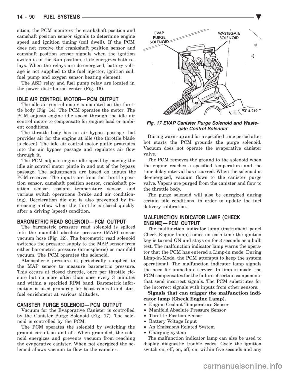
by the Canister Purge Solenoid (Fig. 17). The sole-
noid is controlled by the PCM. The PCM operates the solenoid by switching the
ground circuit on and off. When grounded, the sole-
noid energizes and prevents vacuum from reaching
the evaporative canister. When not energized the so-
lenoid allows vacuum to flow to the canister. During warm-up and for a specified time period after
hot starts the PCM grounds the purge solenoid.
Vacuum does not operate the evaporative canister
valve. The PCM removes the ground to the solenoid when
the engine reaches a specified temperature and the
time delay interval has occurred. When the solenoid is
de-energized, vacuum flows to the canister purge
valve. Vapors are purged from the canister and flow to
the throttle body. The purge solenoid will also be energized during
certain idle conditions, in order to update the fuel
delivery calibration.
MALFUNCTION INDICATOR LAMP (CHECK
ENGINE)ÐPCM OUTPUT
The malfunction indicator lamp (instrument panel
Check Engine lamp) comes on each time the ignition
key is turned ON and stays on for 3 seconds as a bulb
test. The malfunction indicator lamp warns the opera-
tor that the PCM has entered a Limp-in mode. During
Limp-in-Mode, the PCM attempts to keep the system
operational. The malfunction indicator lamp signals
the need for immediate service. In limp-in mode, the
PCM compensates for the failure of certain components
that send incorrect signals. The PCM substitutes for
the incorrect signals with inputs from other sensors. Signals that can trigger the malfunction indi-
cator lamp (Check Engine Lamp).
² Engine Coolant Temperature Sensor
² Manifold Absolute Pressure Sensor
² Throttle Position Sensor
² Battery Voltage Input
² An Emissions Related System
² Charging system
The malfunction indicator lamp can also be used to
display diagnostic trouble codes. Cycle the ignition
switch on, off, on, off, on, within five seconds and any
Fig. 17 EVAP Canister Purge Solenoid and Waste- gate Control Solenoid
14 - 90 FUEL SYSTEMS Ä
Page 1836 of 2438
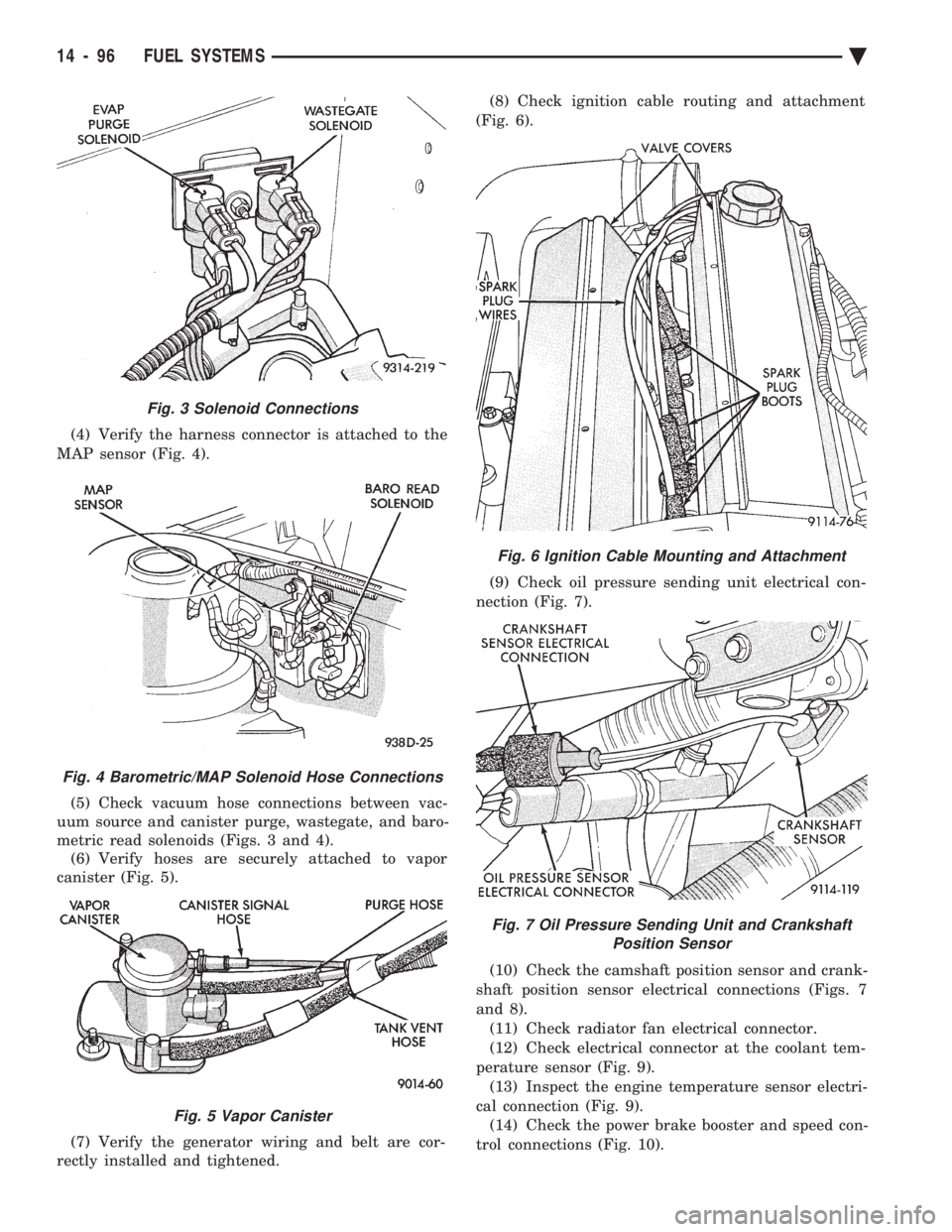
(4) Verify the harness connector is attached to the
MAP sensor (Fig. 4).
(5) Check vacuum hose connections between vac-
uum source and canister purge, wastegate, and baro-
metric read solenoids (Figs. 3 and 4). (6) Verify hoses are securely attached to vapor
canister (Fig. 5).
(7) Verify the generator wiring and belt are cor-
rectly installed and tightened. (8) Check ignition cable routing and attachment
(Fig. 6).
(9) Check oil pressure sending unit electrical con-
nection (Fig. 7).
(10) Check the camshaft position sensor and crank-
shaft position sensor electrical connections (Figs. 7
and 8). (11) Check radiator fan electrical connector.
(12) Check electrical connector at the coolant tem-
perature sensor (Fig. 9). (13) Inspect the engine temperature sensor electri-
cal connection (Fig. 9). (14) Check the power brake booster and speed con-
trol connections (Fig. 10).
Fig. 6 Ignition Cable Mounting and Attachment
Fig. 7 Oil Pressure Sending Unit and Crankshaft Position Sensor
Fig. 3 Solenoid Connections
Fig. 4 Barometric/MAP Solenoid Hose Connections
Fig. 5 Vapor Canister
14 - 96 FUEL SYSTEMS Ä
Page 1837 of 2438
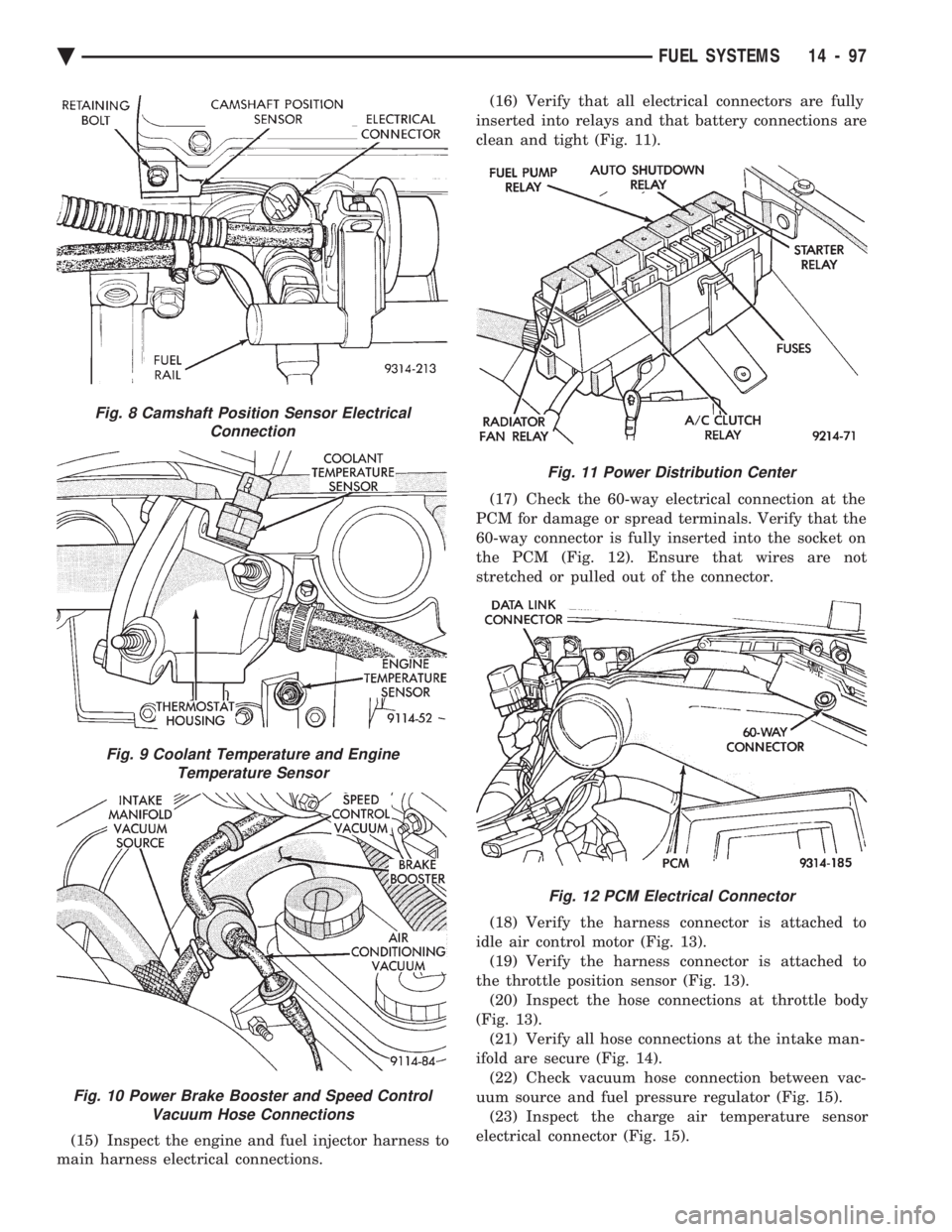
(15) Inspect the engine and fuel injector harness to
main harness electrical connections. (16) Verify that all electrical connectors are fully
inserted into relays and that battery connections are
clean and tight (Fig. 11).
(17) Check the 60-way electrical connection at the
PCM for damage or spread terminals. Verify that the
60-way connector is fully inserted into the socket on
the PCM (Fig. 12). Ensure that wires are not
stretched or pulled out of the connector.
(18) Verify the harness connector is attached to
idle air control motor (Fig. 13). (19) Verify the harness connector is attached to
the throttle position sensor (Fig. 13). (20) Inspect the hose connections at throttle body
(Fig. 13). (21) Verify all hose connections at the intake man-
ifold are secure (Fig. 14). (22) Check vacuum hose connection between vac-
uum source and fuel pressure regulator (Fig. 15). (23) Inspect the charge air temperature sensor
electrical connector (Fig. 15).
Fig. 8 Camshaft Position Sensor Electrical Connection
Fig. 9 Coolant Temperature and EngineTemperature Sensor
Fig. 10 Power Brake Booster and Speed Control Vacuum Hose Connections
Fig. 11 Power Distribution Center
Fig. 12 PCM Electrical Connector
Ä FUEL SYSTEMS 14 - 97
Page 1838 of 2438
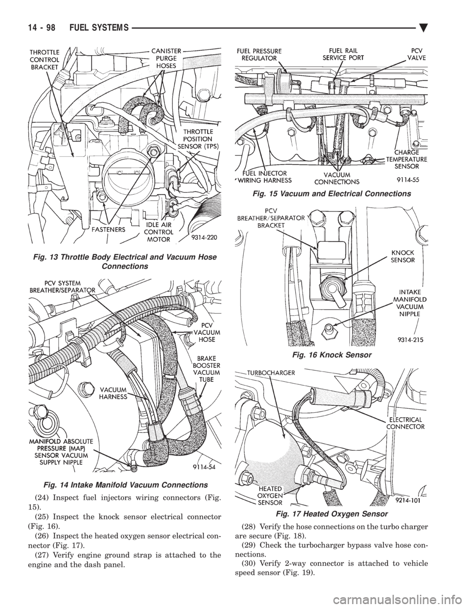
(24) Inspect fuel injectors wiring connectors (Fig.
15). (25) Inspect the knock sensor electrical connector
(Fig. 16). (26) Inspect the heated oxygen sensor electrical con-
nector (Fig. 17). (27) Verify engine ground strap is attached to the
engine and the dash panel. (28) Verify the hose connections on the turbo charger
are secure (Fig. 18). (29) Check the turbocharger bypass valve hose con-
nections. (30) Verify 2-way connector is attached to vehicle
speed sensor (Fig. 19).
Fig. 13 Throttle Body Electrical and Vacuum Hose Connections
Fig. 14 Intake Manifold Vacuum Connections
Fig. 15 Vacuum and Electrical Connections
Fig. 16 Knock Sensor
Fig. 17 Heated Oxygen Sensor
14 - 98 FUEL SYSTEMS Ä