1993 CHEVROLET PLYMOUTH ACCLAIM four wheel drive
[x] Cancel search: four wheel drivePage 290 of 2438

² Left rear wheel
² Right front wheel
(1) Pump brake pedal three or four times, then
hold a constant moderate to heavy foot pressure on
the brake pedal.
CAUTION: Just cracking the bleeder screw often re-
stricts fluid flow, and a slow, weak fluid discharge
will NOT get all the air out.
(2) Open bleeder screw (Fig. 7) at least 1 full turn.
When bleeder screw opens, brake pedal will drop to
the floor. (3) Close bleeder screw. Release brake pedal off
floor only afterbleeder screw is completely closed.
(4) Repeat steps 1 through 3, four or five times, at
each bleeder screw. This should pass a sufficient
amount of brake hydraulic fluid to expel all trapped
air. Be sure to monitor brake fluid level in master
cylinder fluid reservoir. It must stay at a level that
will not allow air to re-enter the hydraulic system
through the master cylinder. After 4 to 8 ounces of hydraulic fluid has been bled
from the bleeder screw at this wheel, and an air-free
flow has been maintained, a good bleed is indicated. Repeat above procedure at all other remaining
bleeder screws, while checking brake pedal for travel. If brake pedal travel is still excessive or has
not improved, enough brake fluid has not passed
through the hydraulic system to expel all trapped
air. Be sure to monitor brake fluid level in the mas-
ter cylinder brake fluid reservoir. It must stay at the
proper level so air will not be allowed to re-enter the
brake system through the master cylinder. Test drive vehicle to be sure brakes are operating
correctly and that pedal is not spongy.
TESTING FOR FLUID CONTAMINATION
Indications of fluid contamination are swollen or
deteriorated rubber parts. Swollen rubber parts indicate the presence of petro-
leum in the brake fluid. To test for contamination, put small amount of
drained brake fluid in clear glass jar. If fluid sepa-
rates into layers, there is mineral oil contamination. If contaminated, drain and thoroughly flush sys-
tem. Replace master cylinder, proportioning valve,
caliper seals, wheel cylinder seals and all hoses.
Fig. 6 Proper Method for Purging Air From Brake System
Fig. 7 Open Bleeder Screw at Least One Full Turn(Typical)
5 - 4 BRAKES Ä
Page 302 of 2438

(2) The voltage output from each of the wheel
speed sensors is verified to be within the correct op-
erating range. If a vehicle is not set in motion within 3 minutes
from the time the ignition switch is turned to the on
position. The solenoid valve test is bypassed but the
pump/motor is activated briefly to verify that it is op-
erating correctly.
WARNING SYSTEMS OPERATION
The ABS system uses an Amber Antilock Warning
Lamp, located in the instrument cluster. The purpose
of the warning lamp is discussed in detail below. The Amber Antilock Warning Light will turn on
whenever the CAB detects a condition which results
in a shutdown of the Antilock brake system. The
Amber Antilock Warning Lamp is normally on until
the CAB completes its self tests and turns the lamp
off (approximately 1-2 seconds). When the Amber
Antilock Warning Light is on, only the Antilock
brake function of the brake system if affected. The
standard brake system and the ability to stop the car
will not be affected when only the Amber Antilock
Warning Light is on.
NORMAL OPERATION OF WARNING LAMP
With ignition key turned to the Crank position, the
Red Brake Warning Lamp and Amber Antilock
Warning Lamp will turn on as a bulb check. The
Amber Antilock Warning Lamp will stay on for 1-2
seconds then turn off, once verification of Antilock
Brake System self diagnosis is completed.
ANTILOCK BRAKE SYSTEM COMPONENTS
The following is a detailed description of the Ben-
dix Antilock 4 Brake System components. For infor-
mation on servicing the Four Wheel Disc Brake
System, see the standard Brake section in the Front
Wheel Drive Car, chassis service manual.
MODULATOR ASSEMBLY
WARNING: THE ONLY COMPONENTS OF THE
MODULATOR ASSSEMBLY THAT ARE SERVICE-
ABLE, ARE THE 2 PROPORTIONING VALVES,
BLEED SCREWS AND THREAD SAVERS. THE RE-
MAINING COMPONENTS OF THE MODULATOR AS-
SEMBLY ARE NOT INTENDED TO BE
SERVICEABLE ITEMS. NO ATTEMPT SHOULD BE
MADE TO REMOVE OR SERVICE ANY OTHER COM-
PONENTS OF THE MODEULATOR ASSEMBLY.
The Modulator Assembly (Fig. 1) is located under
the battery tray and is covered with an acid shield.
The Modulator Assembly contains the following com-
ponents for controlling the Antilock brake system. 4
Build/Decay Valves, 4 Shuttle Orifices, 2 Fluid
Sumps, 2 Accumulators, and a Pump/Motor assem- bly. Also attached to the Modulator Assembly are 6
brake tubes which are connected to a 12 way junc-
tion block. The junction block (Fig. 2) is mounted to
the left frame rail below the master cylinder in the
same location as the non ABS equipped combination
valve. The wheel brake lines are attached to the sys-
tem via the connector block.BUILD/DECAY VALVES
There are 4 Build/Decay valves, one for each
wheel. In the released position they provide a fluid
path direct to the wheel brakes. In the actuated (de-
cay) position, they provide a fluid path from the
wheel brakes to the sump. The Build/Decay valves
are spring loaded in the released (build) position.
SHUTTLE ORIFICE
There are 4 Shuttle Orifice Valves, one for each
wheel. The Shuttle Orifice Valve is a hydraulically
actuated valve which shuttles when the Build/Decay
valve is actuated. Actuating of the Build/Decay valve
causes a pressure differential to be created across the
Shuttle Orifice Valve. This acts like placing an ori-
Fig. 1 Modulator Assembly
Fig. 2 Antilock Brake Junction Block
5 - 16 ANTILOCK 4 BRAKE SYSTEM Ä
Page 745 of 2438
CHIME WARNING/REMINDER SYSTEM
CONTENTS
page page
BODY CONTROLLER REPLACEMENT ........ 5
CHIME MODULE REPLACEMENT AA and AP BODIES .............................. 5
CHIME SYSTEM DIAGNOSISÐAA AND AP BODIES .............................. 2
CHIME SYSTEM DIAGNOSISÐAC, AG, AJ AND AY BODIES ....................... 3
CHIME WARNING/REMINDER SYSTEM TEST . 1 GENERAL INFORMATION
.................. 1
HEADLAMP SWITCH REPLACEMENT ........ 5
KEY-IN SWITCH REPLACEMENT ............ 5
SEAT BELT BUCKLE REPLACEMENT ........ 5
SEAT BELT BUCKLE SWITCH TEST BUZZER SYSTEM .............................. 1
SERVICE PROCEDURES ................... 5
TIMED BUZZER-RELAY TESTÐAP BODY ..... 1
GENERAL INFORMATION
WARNING: ON VEHICLES EQUIPPED WITH AN AIR
BAG REFER TO THE AIR BAG PORTION OF THIS
SECTION FOR STEERING WHEEL OR SWITCH RE-
MOVAL AND INSTALLATION PROCEDURES.
BUZZER SYSTEM
The seat belt warning system uses both visual and
audible signals. A combined seat belt and key warn-
ing buzzer with a red light on the instrument panel. The system will always illuminate the seat belt
warning lamp for four to eight seconds when the ig-
nition switch is turned to the ON position. Also, only
if the driver does not fasten his seat belt, the buzzer
will sound during the same time interval. Passenger
belts are not connected to the system. A timed buzzer-relay is used to operate the system
for the time period. It consists of a time delay mech-
anism and buzzer assembly. Only the driver's seat
belt buckle has a switch that is connected to the sys-
tem.
CHIME WARNING/REMINDER SYSTEM
The chime warning/reminder system is similar in
operation to the buzzer system except for a more
pleasant sounding tone. This chime type tone sounds
for all three warning/reminder conditions; namely
headlamps left on, keys left in ignition and fasten
seat belt.
TIMED BUZZER-RELAY TESTÐAP BODY
PREPARATION
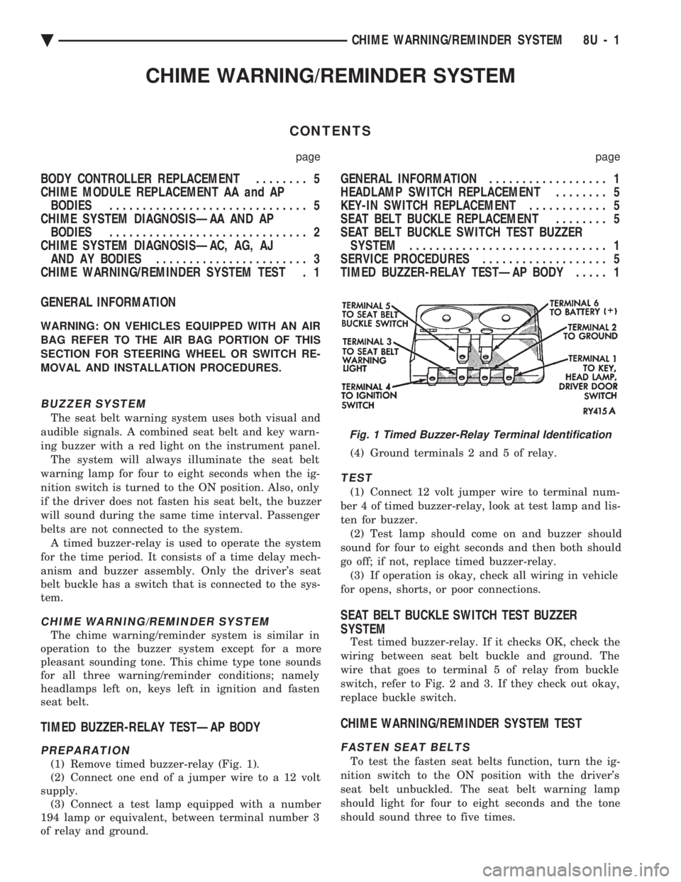
(1) Remove timed buzzer-relay (Fig. 1).
(2) Connect one end of a jumper wire to a 12 volt
supply. (3) Connect a test lamp equipped with a number
194 lamp or equivalent, between terminal number 3
of relay and ground. (4) Ground terminals 2 and 5 of relay.
TEST
(1) Connect 12 volt jumper wire to terminal num-
ber 4 of timed buzzer-relay, look at test lamp and lis-
ten for buzzer. (2) Test lamp should come on and buzzer should
sound for four to eight seconds and then both should
go off; if not, replace timed buzzer-relay. (3) If operation is okay, check all wiring in vehicle
for opens, shorts, or poor connections.
SEAT BELT BUCKLE SWITCH TEST BUZZER
SYSTEM
Test timed buzzer-relay. If it checks OK, check the
wiring between seat belt buckle and ground. The
wire that goes to terminal 5 of relay from buckle
switch, refer to Fig. 2 and 3. If they check out okay,
replace buckle switch.
CHIME WARNING/REMINDER SYSTEM TEST
FASTEN SEAT BELTS
To test the fasten seat belts function, turn the ig-
nition switch to the ON position with the driver's
seat belt unbuckled. The seat belt warning lamp
should light for four to eight seconds and the tone
should sound three to five times.
Fig. 1 Timed Buzzer-Relay Terminal Identification
Ä CHIME WARNING/REMINDER SYSTEM 8U - 1
Page 1580 of 2438
CAUTION: Make sure clutch cable has been discon-
nected. (20) Remove front engine mount screw and nut.
(21) Remove manual transmission damper.
(22) Remove left insulator through bolt from inside
wheelhouse or insulator bracket to transmission
screws. (23) Remove engine from vehicle.
INSTALLATION
(1) Install hoist to the engine and lower engine
into the engine compartment. SEE: ENGINE MOUNT RUBBER INSULATORS,
THIS GROUP. (2) Align engine mounts and install but do not
tighten until all mounting bolts have been installed.
(3) Install transmission case to cylinder block
mounting screws. Tighten to 95 N Im (70 ft. lbs.)
torque. (4) Remove engine hoist and transmission holding
fixture. (5) Install ground strap.
(6) Install right inner splash shield.
(7) Connect starter. See Electrical Group 8 for in-
stallation. (8) Connect exhaust system. See Exhaust Systems
Group 11 for installation. (9) Manual Transmission: Install transmission
case lower cover. Automatic Transmission: Remove C clamp from
torque converter housing. Align flexplate to torque
converter and install mounting screws. Tighten to 75
N Im (55 ft. lbs.) torque.
(10) Manual Transmission: Connect clutch cable.
See Clutch Group 6. (11) Install power steering pump. Refer to Cooling
System Group 7, Accessory Drive Section for belt
tension adjustment. (12) Connect fuel line, heater hose, and accelerator
cable. (13) Connect all electrical connections and har-
nesses at throttle body and engine. (14) Install oil filter. Fill engine crankcase with
proper oil to correct level. (15) Install air conditioning compressor (if
equipped). See Heater and Air Conditioning, Group
24 for installation. (16) Install air cleaner and hoses.
(17) Install radiator and shroud assembly . Install
radiator hoses. Fill cooling system. See Cooling Sys-
tem Group 7 for filling procedure. (18) Install hood.
(19) Connect battery.
(20) Start engine and run until operating temper-
ature is reached. (21) Adjust transmission linkage, if necessary.
SOLID MOUNT COMPRESSOR BRACKET SERVICE
When service procedures require solid mount
bracket removal and installation for example: cylin-
der head removal, etc., it is important that bracket
fasteners numbered 1 through 7 (Fig. 4) be removed
and installed in sequence, as instructed in Remove
and Install.
ACCESSORIES REMOVAL
(1) Remove (and install/adjust) belts,see Accessory
Drive Belts in Cooling System,Group 7. (2) Remove air conditioning compressor (in vehicle
with lines and set aside) (Fig. 6). (3) Remove generator pivot bolt and remove gener-
ator (in vehicle: turn wiring side up and disconnect,
then rotate generator, pulley end towards engine and
remove). (4) Remove air conditioner compressor belt idler.
SOLID MOUNT BRACKETÐREMOVAL (FIG. 4)
(1) Remove right engine mount yoke screw (see
Engine Remove Fig. 3) securing engine mount sup-
port strut to engine mount bracket. (2) Remove five side mounting bolts #1, #4 , #5,
#6, and #7 (Fig. 4). (3) Remove front mounting nut, #2, and remove
front bolt #3*. (4) Remove front mounting bolt and strut, rotate
solid mount bracket away from engine and slide
bracket on stud until #2 nut mounting stud until
free. Remove spacer from stud.
SOLID MOUNT BRACKETÐINSTALLATION
(1) Put spacer onto stud, then install bracket on
front (#2 nut) mounting stud and slide bracket over
timing belt cover into position. (2) Loosen assembly bracket to engine fasteners
(numbered #1 through #7 in Fig. 6). (3)
CAUTION: Fasteners MUST BE TIGHTENED IN SE-
QUENCE and to specified torque as follows :
² First Bolt #1 to 3.3 N Im (30 in. lbs.)
² Second Nut #2 and Bolt #3 to 54 N Im (40 ft. lbs.).
² Third Bolts #1 (second tightening) #4 and #5 to
54 N Im (40 ft. lbs.).
² Fourth Bolts #6 and #7 to 54 N Im (40 ft. lbs.).
(4) Install generator and compressor. Tighten com-
pressor mounting bracket bolts to 54 N Im (40 ft.
lbs.).
SOLID MOUNT COMPRESSOR BRACKET SERVICEÐTURBO III ENGINE
REMOVAL
(1) Disconnect negative battery cable
9 - 14 2.2/2.5L ENGINE Ä
Page 1598 of 2438
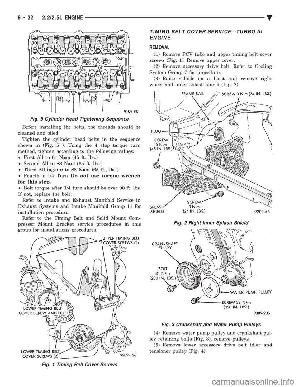
Before installing the bolts, the threads should be
cleaned and oiled. Tighten the cylinder head bolts in the sequence
shown in (Fig. 5 ). Using the 4 step torque turn
method, tighten according to the following values:
² First All to 61 N Im (45 ft. lbs.)
² Second All to 88 N Im (65 ft. lbs.)
² Third All (again) to 88 N Im (65 ft., lbs.)
² Fourth + 1/4 Turn Do not use torque wrench
for this step.
² Bolt torque after 1/4 turn should be over 90 ft. lbs.
If not, replace the bolt. Refer to Intake and Exhaust Manifold Service in
Exhaust Systems and Intake Manifold Group 11 for
installation procedure. Refer to the Timing Belt and Solid Mount Com-
pressor Mount Bracket service procedures in this
group for installations procedures.
TIMING BELT COVER SERVICEÐTURBO III
ENGINE
REMOVAL
(1) Remove PCV tube and upper timing belt cover
screws (Fig. 1). Remove upper cover. (2) Remove accessory drive belt. Refer to Cooling
System Group 7 for procedure. (3) Raise vehicle on a hoist and remove right
wheel and inner splash shield (Fig. 2).
(4) Remove water pump pulley and crankshaft pul-
ley retaining bolts (Fig. 3), remove pulleys. (5) Remove lower accessory drive belt idler and
tensioner pulley (Fig. 4).
Fig. 1 Timing Belt Cover Screws
Fig. 5 Cylinder Head Tightening Sequence
Fig. 2 Right Inner Splash Shield
Fig. 3 Crankshaft and Water Pump Pulleys
9 - 32 2.2/2.5L ENGINE Ä
Page 1919 of 2438
STEERING
CONTENTS
page page
ACUSTAR STANDARD AND TILT STEERING COLUMN ............................ 28
AUTOMATIC TRANSMISSION SHIFTER/IGNITION INTERLOCK .......................... 36
GENERAL INFORMATION .................. 1 POWER STEERING GEAR
................ 25
POWER STEERING PUMPS ................ 1
SPECIFICATIONS AND TIGHTENING REFERENCE .......................... 42
GENERAL INFORMATION
Safety goggles should be worn at all times
when working on any steering gear or pump. Throughout this group, references may be made to
a particular vehicle by letter or number designation.
A chart showing the breakdown of these designations
is included in the Introduction Section at the front of
this service manual. The power steering system consists of these four
major components. Power Steering Pump, Power
Steering Gear, Pressure Hose, and Return Line.
Turning of the steering wheel is converted into lin-
ear travel through the meshing of the helical pinion teeth with the rack teeth. Power assist steering is
provided by an open center, rotary type control valve.
It is used to direct oil from the power steering pump
to either side of the integral steering rack piston. Road feel is controlled by the diameter of a torsion
bar which initially steers the vehicle. As steering ef-
fort increases as in a turn, the torsion bar twists,
causing relative rotary motion between the rotary
valve body and valve spool. This movement directs
oil behind the integral rack piston, which in turn,
builds up hydraulic pressure and assists in the turn-
ing effort.
POWER STEERING PUMPS
INDEX
page page
Checking Power Steering Fluid Level .......... 9
Flow Control Valve Fitting O-Ring Seal ........ 23
General Information ........................ 1
Power Steering Hoses ..................... 11
Power Steering Pressure Switch ............. 10
Power Steering Pump Fluid Reservoirs ........ 22 Power Steering Pump Pressure Test
........... 9
Power Steering Pump Pulley Service .......... 20
Power Steering Pump Removal .............. 12
Power Steering Pump Service ................ 2
Power Steering PumpÐInitial Operation ....... 24
Steering Components Service Diagnosis ........ 2
GENERAL INFORMATION
Hydraulic pressure for operation of the power
steering gear is provided by a belt driven power
steering pump. The power steering pump is a con-
stant flow rate and displacement, vane type pump.
Different styles of Saginaw power steering pumps are
used depending on the engine application of the ve-
hicle. On all four cylinder and 3.0-liter V-6 applications
the Saginaw Ham Can power steering pump is used
(Fig. 1). On the 3.3 & 3.8-liter V-6 and Turbo III applica-
tions, different versions of the Saginaw T/C style
power steering pump is used (Fig. 2). The 3.3 & 3.8 liter V-6 engine application uses the T/C style power
steering pump with a remote mounted reservoir for
the power steering fluid. On the Turbo III application
of the T/C style power steering pump, the power
steering fluid reservoir is integral to the power steer-
ing pump. On the integral reservoir type pump (Fig. 1) the
pump housing and internal components are combined
with the reservoir to form a one-piece mechanism. The Saginaw T/C style power steering pump (Fig.
2), consists of the power steering pump internal com-
ponents and pump housing. The Saginaw T/C style
power steering pump though has no internal reser-
voir for the power steering fluid. Depending on vehi-
Ä STEERING 19 - 1
Page 1943 of 2438
POWER STEERING GEAR INDEX
page page
General Information ....................... 25
Outer Tie Rod ........................... 27 Steering Gear Service
..................... 25
GENERAL INFORMATION
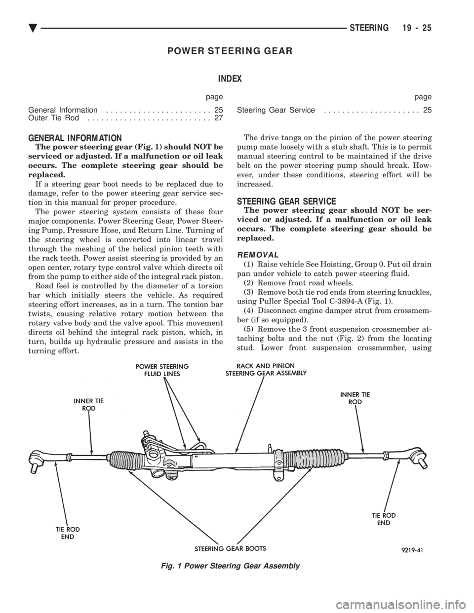
The power steering gear (Fig. 1) should NOT be
serviced or adjusted. If a malfunction or oil leak
occurs. The complete steering gear should be
replaced. If a steering gear boot needs to be replaced due to
damage, refer to the power steering gear service sec-
tion in this manual for proper procedure. The power steering system consists of these four
major components. Power Steering Gear, Power Steer-
ing Pump, Pressure Hose, and Return Line. Turning of
the steering wheel is converted into linear travel
through the meshing of the helical pinion teeth with
the rack teeth. Power assist steering is provided by an
open center, rotary type control valve which directs oil
from the pump to either side of the integral rack piston. Road feel is controlled by the diameter of a torsion
bar which initially steers the vehicle. As required
steering effort increases, as in a turn. The torsion bar
twists, causing relative rotary motion between the
rotary valve body and the valve spool. This movement
directs oil behind the integral rack piston, which, in
turn, builds up hydraulic pressure and assists in the
turning effort. The drive tangs on the pinion of the power steering
pump mate loosely with a stub shaft. This is to permit
manual steering control to be maintained if the drive
belt on the power steering pump should break. How-
ever, under these conditions, steering effort will be
increased.
STEERING GEAR SERVICE
The power steering gear should NOT be ser-
viced or adjusted. If a malfunction or oil leak
occurs. The complete steering gear should be
replaced.
REMOVAL
(1) Raise vehicle See Hoisting, Group 0. Put oil drain
pan under vehicle to catch power steering fluid. (2) Remove front road wheels.
(3) Remove both tie rod ends from steering knuckles,
using Puller Special Tool C-3894-A (Fig. 1). (4) Disconnect engine damper strut from crossmem-
ber (if so equipped). (5) Remove the 3 front suspension crossmember at-
taching bolts and the nut (Fig. 2) from the locating
stud. Lower front suspension crossmember, using
Fig. 1 Power Steering Gear Assembly
Ä STEERING 19 - 25
Page 2055 of 2438
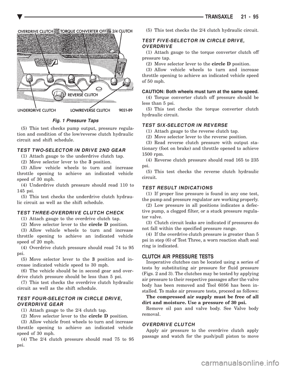
(5) This test checks pump output, pressure regula-
tion and condition of the low/reverse clutch hydraulic
circuit and shift schedule.
TEST TWO-SELECTOR IN DRIVE 2ND GEAR
(1) Attach gauge to the underdrive clutch tap.
(2) Move selector lever to the 3position.
(3) Allow vehicle wheels to turn and increase
throttle opening to achieve an indicated vehicle
speed of 30 mph. (4) Underdrive clutch pressure should read 110 to
145 psi. (5) This test checks the underdrive clutch hydrau-
lic circuit as well as the shift schedule.
TEST THREE-OVERDRIVE CLUTCH CHECK
(1) Attach gauge to the overdrive clutch tap.
(2) Move selector lever to the circle Dposition.
(3) Allow vehicle wheels to turn and increase
throttle opening to achieve an indicated vehicle
speed of 20 mph. (4) Overdrive clutch pressure should read 74 to 95
psi. (5) Move selector lever to the 3position and in-
crease indicated vehicle speed to 30 mph. (6) The vehicle should be in second gear and over-
drive clutch pressure should be less than 5 psi. (7) This test checks the overdrive clutch hydraulic
circuit as well as the shift schedule.
TEST FOUR-SELECTOR IN CIRCLE DRIVE, OVERDRIVE GEAR
(1) Attach gauge to the 2/4 clutch tap.
(2) Move selector lever to the circle Dposition.
(3) Allow vehicle front wheels to turn and increase
throttle opening to achieve an indicated vehicle
speed of 30 mph. (4) The 2/4 clutch pressure should read 75 to 95
psi. (5) This test checks the 2/4 clutch hydraulic circuit.
TEST FIVE-SELECTOR IN CIRCLE DRIVE,
OVERDRIVE
(1) Attach gauge to the torque converter clutch off
pressure tap. (2) Move selector lever to the circle Dposition.
(3) Allow vehicle wheels to turn and increase
throttle opening to achieve an indicated vehicle speed
of 50 mph.
CAUTION: Both wheels must turn at the same speed. (4) Torque converter clutch off pressure should be
less than 5 psi. (5) This test checks the torque converter clutch
hydraulic circuit.
TEST SIX-SELECTOR IN REVERSE
(1) Attach gauge to the reverse clutch tap.
(2) Move selector lever to the reverse position.
(3) Read reverse clutch pressure with output sta-
tionary (foot on brake) and throttle opened to achieve
1500 rpm. (4) Reverse clutch pressure should read 165 to 235
psi. (5) This test checks the reverse clutch hydraulic
circuit.
TEST RESULT INDICATIONS
(1) If proper line pressure is found in any one test,
the pump and pressure regulator are working properly. (2) Low pressure in all positions indicates a defec-
tive pump, a clogged filter, or a stuck pressure regula-
tor valve. (3) Clutch circuit leaks are indicated if pressures do
not fall within the specified pressure range. (4) If the overdrive clutch pressure is greater than 5
psi in step (6) of Test Three, a worn reaction shaft seal
ring is indicated.
CLUTCH AIR PRESSURE TESTS
Inoperative clutches can be located using a series of
tests by substituting air pressure for fluid pressure
(Figs. 2 and 3). The clutches may be tested by applying
air pressure to their respective passages after the valve
body has been removed and Tool 6056 has been in-
stalled. To make air pressure tests, proceed as follows: The compressed air supply must be free of all
dirt and moisture. Use a pressure of 30 psi. Remove oil pan and valve body. See Valve body
removal.
OVERDRIVE CLUTCH
Apply air pressure to the overdrive clutch apply
passage and watch for the push/pull piston to move
Fig. 1 Pressure Taps
Ä TRANSAXLE 21 - 95