1993 CHEVROLET PLYMOUTH ACCLAIM key
[x] Cancel search: keyPage 2065 of 2438
If screen (c) appears, the transmission control mod-
ule has completed its break-in status program. Press
the enter key on the DRB II scan tool key pad to return
the status to the start of break-in. (9) After pressing the enter key a second time in step
8 a screen will appear that says ``RESET LU CLUTCH
ARE YOU SURE ?''. Press the enter key on the DRB II
scan tool key pad. The DRB II scan tool will then carry
out the reset command. (10) After the DRB II scan tool completes the reset
command, a screen will appear saying ``LU Clutch
Break-in Status has been RESET to Start''. This screen
will indicate that the reset procedure has been success-
fully completed. (11) Disconnect the DRB II scan tool from the blue
CCD Bus connector.
TRANSAXLE RECONDITION
Tag all clutch pack assemblies, as they are
removed, for reassembly identification.
CAUTION: Do not intermix clutch discs or plates as
the unit might then fail.
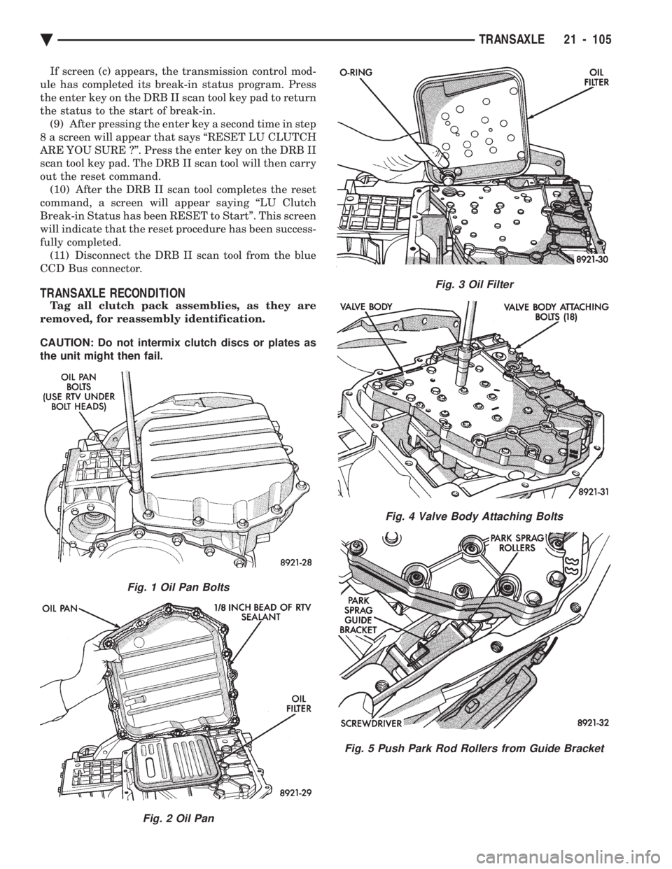
Fig. 1 Oil Pan Bolts
Fig. 2 Oil Pan
Fig. 3 Oil Filter
Fig. 4 Valve Body Attaching Bolts
Fig. 5 Push Park Rod Rollers from Guide Bracket
Ä TRANSAXLE 21 - 105
Page 2105 of 2438
41TE ON-BOARD DIAGNOSTICS INDEX
page page
CCD Bus .............................. 145
Diagnostic Trouble Code Charts ............ 146
Diagnostic Trouble Codes ................. 145
DRB II Scan Tool ....................... 146 General Information
...................... 145
Limp-In Mode .......................... 145
On-Board Diagnostics Information ........... 145
GENERAL INFORMATION
The information in this manual is designed to help
the technician understand and repair the transaxle
with the aid of the built in on-board diagnostics. Chrysler Corporation has developed a com-
plete set of diagnostic manuals which cover the
diagnosis of the 41TE transaxle. They have been
designed to make transaxle diagnosis accurate
and simple. Use these manuals with the DRB II
scan tool and the latest cartridge, when diagnos-
ing transaxle problems.
ON-BOARD DIAGNOSTICS INFORMATION
The 41TE transaxle is controlled and monitored by
the transmission control module. The transmission
control module monitors critical input and output
circuits within the transaxle. Some circuits are tested continuously; others are
checked only under certain conditions. Each circuit
monitored by the transmission control module has a
corresponding fault message assigned to it that can be
read with the DRB II scan tool. If the on-board diagnostic system senses that one of
the circuits is malfunctioning, the corresponding code
is stored in memory. If the malfunction goes away after
the code is stored, the transmission control module will
erase the code after 75 key cycles.
CCD BUS
In order to diagnose the 41TE transaxle, diagnostic
trouble codes in the transmission control module's
memory should be read. Use the Diagnostic Readout
Box (DRB II) scan tool to read codes. If more than one
diagnostic trouble code exists, diagnostic priority
should be given to the most recent code. With CCD bus
bias and communication problems, the DRB II scan
tool displays an appropriate message. Diagnostic
trouble codes might not be accessible until the bus
problem is fixed. The following is a list of probable
causes for a bus problem:
² Open or short to ground/battery in either or both
CCD bus wires (pins 4 and 43).
² Open or short to ground/battery in either or both
41TE transaxle's bias wires (pin 5 and 44) on vehicles
requiring the transaxle to bias the bus.
² Open or short to ground/battery in the diagnostic
connector bus wire. ²
Internal failure of any module connected to the bus.
The CCD bus should have 2.5 volts (+2.5 volts on
CCD+ and -2.5 volts on CCD-). The bus error message displayed by the DRB II scan
tool should be helpful in diagnosing the CCD bus. For more information on diagnosing CCD bus prob-
lems, refer to the 1993 Diagnostic Procedures Manual
(non-communication with the CCD bus). All other
problems refer to the 1993 Body Vehicle Communica-
tions Diagnostic Procedures Manual.
DIAGNOSTIC TROUBLE CODES
Diagnostic Trouble Codes are two-digit numbers that
identify which circuit is malfunctioning. A code can be
set for hydraulic and mechanical reasons as well as for
electrical problems. In most cases, codes do not pin-
point which specific component is defective. Diagnostic trouble codes can only be read with
the use of the DRB II scan tool or equivalent.
HARD FAULTS
Any Diagnostic trouble code that comes back within
3 engine starts (reset count 3 or less) is a ``Hard Fault''.
This means that the defect is there every time the
transmission control module checks that circuit.
SOFT FAULTS
A ``Soft Fault'' is one that occurs intermittently. It is
not there every time the transmission control module
checks the circuit. Most soft faults are caused by wiring
or connector problems. Intermittent defects must be
looked for under the specific conditions that caused
them.
LIMP-IN MODE
The transmission control module continuously
checks for electrical and internal transaxle problems.
When a problem is sensed, the transmission control
module stores a diagnostic trouble code. All but twelve
of these codes cause the transaxle to go into the
``Limp-in mode''. While in this mode, electrical power is
taken away from the transaxle. When this happens,
the only transaxle ranges that will function are:
Ä TRANSAXLE 21 - 145
Page 2246 of 2438
(8) Position zipper upper half listing at index
marks on the third roof bow. Verify that start end of
zipper upper half is at the same end as the rear win-
dow half. (9) Install staples to hold zipper listing to third
roof bow (Fig. 8). (10) Position top cover hold down listing at index
marks on third roof bow. (11) Install staples to hold top cover listing to third
roof bow (Fig. 8). (12) Position stay straps at index marks on the
third roof bow. (13) Install staples to hold stay straps to third roof
bow. (14) Zip rear window into position.
(15) Fold rear of top cover, tack strips and rear
window up and over the third roof bow to the rear of
the top opening (Fig. 8). (16) Position top cover at index marks at each end
of rear tack strip. (17) Install staples to hold top cover to rear tack
strip (Fig. 6). (18) Position side and rear tack strips behind quar-
ter and deck panels. (19) Install bolts to hold side tack strips to inside
of quarter panels (Fig. 6). (20) Install bolts to hold rear tack strip to deck
panel. (21) Latch top header to windshield header and in-
spect top cover for excess wrinkling. If wrinkling is
apparent, the top cover and rear window apron must
be repositioned on the tack strips. (22) Route wire harnesses through pockets at each
side of window and connect ends to terminals on
glass. (23) Install sling well and rear section of headlin-
ing.
FOLDING TOP COVER
REMOVAL
(1) Release folding top latches and allow top cover
to relax. (2) Remove headlining.
(3) Disengage snaps holding top storage sling well
to rear deck and quarter panels. (4) Position sling well out of the way.
(5) Remove bolts holding rear tack strip to inner
deck panel. (6) Separate rear tack strip from deck panel.
(7) Remove bolts holding side tack strips to inside
of quarter panels. (8) Separate tack strips from quarter panels.
CAUTION: Cover all painted and upholstered sur-
faces to avoid damage while performing the follow-
ing operations. (9) Reposition tack strips above rear deck and
quarter panels. (10) Using a grease pencil, mark location of outer
top cover on rear tack strip to aid installation. (11) Remove staples holding top cover to rear tack
strip. (12) Fold rear of top cover, tack strips and rear
window up and over the third (rear) roof bow. (13) Unzip and separate rear window from vehicle.
(14) Mark location of top cover hold down listing
on third roof bow. (15) Remove staples holding top cover listing to
third roof bow. (16) Remove screws holding roof rail tension cable
springs to roof rear roof rail behind quarter glass
opening. (17) Pull quarter glass weatherstrips from roof rail
channels. (18) Remove screws holding roof rail channels to
roof rails. (19) Separate roof rail channels from vehicle.
(20) Separate top cover listing from adhesive on
roof rail. (21) Lower folding top to the mid point.
(22) Pull top header weatherstrip from retaining
channel. Separate first 50 mm (2 in.) of weather strip
from roof rail channels. (23) Remove screws holding weatherstrip channel
to top header. (24) Separate channel from top header.
(25) Remove staples holding top header feature
strip to top header. (26) Separate feature strip from header.
(27) Mark location or top cover on top header.
(28) Remove staples holding top cover to header.
(29) Close folding top, do not latch.
(30) Remove rubber plugs holding roof rail tension
cable ends into key-hole slots in roof rails (31) Disengage roof rail tension cables from roof
rails. (32) Pull tension cables from rear of pockets on
back of top cover. (33) Remove screws holding top cover retainer rod
to second roof bow. (34) Separate retainer rod from second roof bow.
(35) Remove screws holding top cover retainer rod
to first roof bow. (36) Separate retainer rod from first roof bow.
(37) Separate top cover from vehicle.
(38) Pull retainer rod from listing pockets on back
of top cover.
INSTALLATION
The new top cover must be trimmed to the same
size and shape as the old top cover to minimize wrin-
kling after installation. Use the rear sections of the
old top as a pattern.
23 - 90 AJ/27-BODY Ä
Page 2247 of 2438
(1) On old top cover mark a line from the top of
the quarter glass opening to the center of rear glass
opening on each side of the top. (2) Using a suitable cutting tool, cut the rear quar-
ter sections off of old top. (3) Mark locations of old top cover on side tack
strips. (4) Remove staples holding old top cover to side
tack strips. (5) Using quarter sections cut from old top cover as
a pattern, mark lower tack strip edge of new top to
same size and shape as old top. (6) Trim excess material from new top cover.
(7) Position side tack strips under edge of new top
and align index marks. (8) Install staples 100 mm (4 in.) apart to hold top
cover to side tack strips. (9) Install retainer rod in listing pockets on back of
top cover. (10) Position top cover over top bows on vehicle
and center top cover side to side. (11) Mate retainer rod to first roof bow.
(12) Install screws to hold top cover retainer rod to
first roof bow. (13) Mate retainer rod to second roof bow.
(14) Install screws to hold top cover retainer rod to
second roof bow. (15) Route roof rail tension cables through rear of
pockets on back of top cover. (16) Connect roof rail tension cables to key-hole
slots in roof rails. (17) Install rubber plugs to hold roof rail tension
cable ends into key-hold slots in roof rails. (18) Apply suitable contact adhesive to roof rail
rear of quarter glass opening and back of top cover
hold down listing. (19) Stick top cover listing to roof rail.
(20) Place roof rail weatherstrip channel in proper
position. (21) Install screws to hold channel to roof rail.
(22) Position top cover listing at index marks on
third roof bow. (23) Install staples 10 mm (0.3 in.) apart to hold
top cover listing to third roof bow. (24) Zip rear window into position.
(25) Fold rear of top cover, tack strips and rear
window down and over the third roof bow. (26) Position top cover at index marks on rear tack
strip. (27) Install staples 100 mm (4 in.) apart to hold
top cover to rear tack strip.
CAUTION: Cover all painted and upholstered sur-
faces to avoid damage while performing the follow-
ing operations.
(28) Reposition tack strips under rear deck and
quarter panels. (29) Place side tack strips in position behind quar-
ter panels. (30) Install enough bolts to temporarily hold side
tack strips to inside of quarter panels. (31) Place rear tack strip in position behind deck
panel. (32) Install enough bolts to temporarily hold rear
tack strip to inner deck panel. (33) Close and latch folding top.
(34) Pull top cover forward over top of windshield
and hold cover material taut. (35) Mark location of froward lower edge of top
header on top cover material. (36) Release top latches and lower top to mid-
point. (37) Align marks on top material to front lower
edge of top header. (38) Verify that top cover will be wrinkle free and
aligned side to side. (39) Install staples 10 mm (0.3 in.) apart to hold
top cover to header. (40) Place top header feature strip in position un-
der top header. (41) Install staples 10 mm (0.3 in.) apart to hold
feature strip to top header. (42) Place weatherstrip channel in position under
top header. (43) Install screws to hold channel to top header.
(44) Insert top header weatherstrip into header
and roof rail channels. (45) Install screws to hold roof rail tension cable
springs to roof rear roof rail behind quarter glass
opening. (46) Close and latch top windshield header.
(47) Inspect top cover for excess wrinkling. If ex-
cess wrinkles are apparent, the top cover must be re-
positioned on the tack strips. (48) If top cover is smooth, release top header
latches to allow top cover to relax. (49) Remove bolts holding tack strips to deck and
quarter panels. (50) Install staples 10 mm (0.3 in.) apart to hold
top cover to rear and side tack strips. (51) Place side and rear tack strips in position.
(52) Install bolts to hold tack strips to deck and
quarter panels. (53) Insert quarter glass weatherstrips into roof
rail channels. (54) Place sling well into position.
(55) Engage snaps to hold sling well to rear deck
and quarter panels. Verify that drain tube is con-
nected to bottom of sling well. (56) Install headlining.
(57) Close top and latch header to windshield
header.
Ä AJ/27-BODY 23 - 91
Page 2323 of 2438
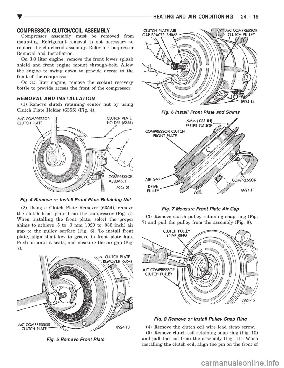
COMPRESSOR CLUTCH/COIL ASSEMBLY
Compressor assembly must be removed from
mounting. Refrigerant removal is not necessary to
replace the clutch/coil assembly. Refer to Compressor
Removal and Installation. On 3.0 liter engine, remove the front lower splash
shield and front engine mount through-bolt. Allow
the engine to swing down to provide access to the
front of the compressor. On 3.3 liter engine, remove the coolant recovery
bottle to provide access the front of the compressor.
REMOVAL AND INSTALLATION
(1) Remove clutch retaining center nut by using
Clutch Plate Holder (6355) (Fig. 4).
(2) Using a Clutch Plate Remover (6354), remove
the clutch front plate from the compressor (Fig. 5).
When installing the front plate, select the proper
shims to achieve .5 to .9 mm (.020 to .035 inch) air
gap to the pulley surface (Fig. 6). To install front
plate, align shaft key to groove in front plate hub.
Push on until it seats, and measure the air gap (Fig.
7). (3) Remove clutch pulley retaining snap ring (Fig.
7) and pull the pulley from the assembly (Fig. 8).
(4) Remove the clutch coil wire lead strap screw.
(5) Remove clutch coil retaining snap ring (Fig. 10)
and pull the coil from the assembly (Fig. 11). When
installing the clutch coil, align the pin on the front of
Fig. 4 Remove or Install Front Plate Retaining Nut
Fig. 5 Remove Front Plate
Fig. 6 Install Front Plate and Shims
Fig. 7 Measure Front Plate Air Gap
Fig. 8 Remove or Install Pulley Snap Ring
Ä HEATING AND AIR CONDITIONING 24 - 19
Page 2324 of 2438
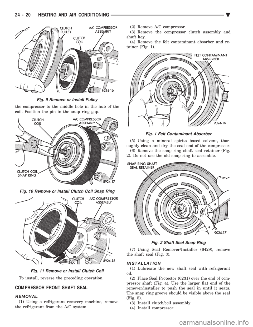
the compressor to the middle hole in the hub of the
coil. Position the pin in the snap ring gap.
To install, reverse the preceding operation.
COMPRESSOR FRONT SHAFT SEAL
REMOVAL
(1) Using a refrigerant recovery machine, remove
the refrigerant from the A/C system. (2) Remove A/C compressor.
(3) Remove the compressor clutch assembly and
shaft key. (4) Remove the felt contaminant absorber and re-
tainer (Fig. 1).
(5) Using a mineral spirits based solvent, thor-
oughly clean and dry the seal end of the compressor. (6) Remove the snap ring shaft seal retainer (Fig.
2). Do not use the old snap ring to assemble.
(7) Using Seal Remover/Installer (6429), remove
the shaft seal (Fig. 3).
INSTALLATION
(1) Lubricate the new shaft seal with refrigerant
oil. (2) Place Seal Protector (6231) over the end of com-
pressor shaft (Fig. 4). Use the larger flat end of the
remover/installer to push the seal in until it seats.
The snap ring groove should be visible above the seal
(Fig. 5). (3) Install clutch/coil assembly.
(4) Install compressor.
Fig. 9 Remove or Install Pulley
Fig. 10 Remove or Install Clutch Coil Snap Ring
Fig. 11 Remove or Install Clutch Coil
Fig. 1 Felt Contaminant Absorber
Fig. 2 Shaft Seal Snap Ring
24 - 20 HEATING AND AIR CONDITIONING Ä
Page 2342 of 2438
FIXED DISPLACEMENT COMPRESSORÐMODEL SD709P INDEX
page page
Compressor ............................. 38
Compressor Clutch/Coil Assembly ............ 38
Compressor Shaft Seal .................... 41 Cylinder Head/Valve Plate
.................. 44
Description ............................. 38
Refrigerant System Diagnosis ............... 45
DESCRIPTION
The Sanden compressor is a 7 piston design. Sys-
tem lubrication is provided by 135 ml 615 ml (4.6 oz.
6 0.5 oz.) of 500 viscosity refrigerant oil.
The clutch used on the compressor consists of 3 ba-
sic components:
² The pulley
² Front plate
² Field coil
The pulley and field coil are attached to the front
head of the compressor with tapered snap rings. The
hub is keyed to the compressor shaft and is retained
on the shaft with a self-locking nut. Special service
tools are required to remove and install the clutch
plate on the compressor shaft.
COMPRESSOR
The A/C compressor may be removed and posi-
tioned without discharging the refrigerant system.
Discharging is not necessary if removing the A/C
compressor clutch/coil assembly, engine, cylinder
head, or generator.
WARNING: REFRIGERANT PRESSURES REMAIN
HIGH EVEN THOUGH THE ENGINE MAY BE
TURNED OFF. BEFORE REMOVING A FULLY
CHARGED COMPRESSOR, REVIEW THE SAFETY
PRECAUTIONS AND WARNINGS SECTION IN THIS
GROUP. DO NOT TWIST OR KINK THE REFRIGER-
ANT LINES WHEN REMOVING A FULLY CHARGED
COMPRESSOR. SAFETY GLASSES MUST BE
WORN.
REMOVAL
(1) Disconnect negative cable from battery.
(2) Loosen and remove drive belts (refer to group
7, Cooling System) and disconnect compressor clutch
wire lead. (3) Remove refrigerant lines from compressor (if
necessary). (4) Remove compressor attaching nuts and bolts.
(5) Remove compressor. If refrigerant lines were
not removed, lift compressor/clutch assembly and tie
it to a suitable component. To install, reverse the removal procedure.
COMPRESSOR CLUTCH/COIL ASSEMBLY
The magnetic clutch consists of a stationary elec-
tro-magnetic coil and a rotating pulley and plate as-
sembly. The electromagnetic coil is retained on the com-
pressor with a snap ring and is dimpled to maintain
its position. The pulley and plate assembly are mounted on the
compressor shaft. When the compressor is not in operation, the pul-
ley free wheels on the clutch hub bearing. When the
coil is energized the plate is magnetically engaged
with the pulley and turns the compressor shaft.
REMOVAL
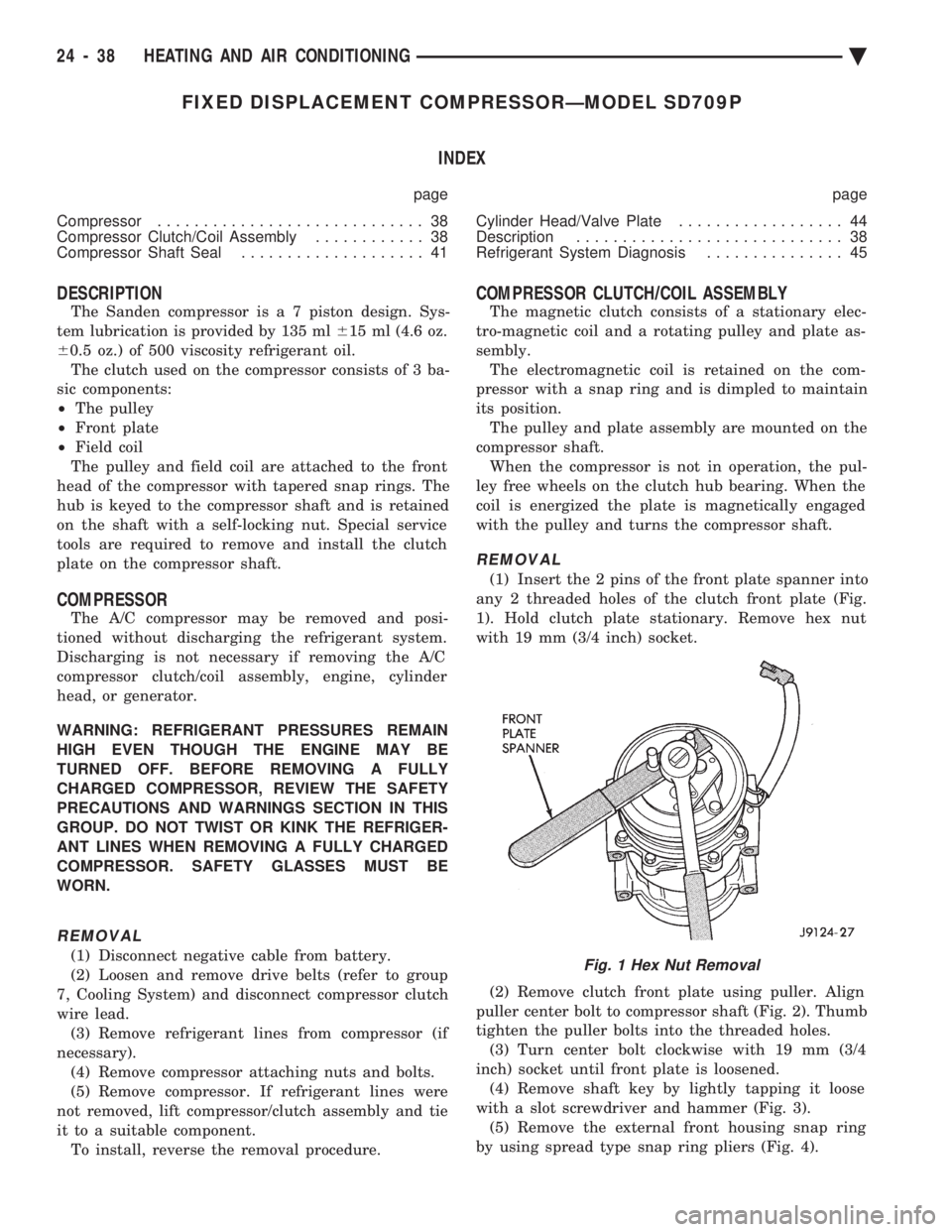
(1) Insert the 2 pins of the front plate spanner into
any 2 threaded holes of the clutch front plate (Fig.
1). Hold clutch plate stationary. Remove hex nut
with 19 mm (3/4 inch) socket.
(2) Remove clutch front plate using puller. Align
puller center bolt to compressor shaft (Fig. 2). Thumb
tighten the puller bolts into the threaded holes. (3) Turn center bolt clockwise with 19 mm (3/4
inch) socket until front plate is loosened. (4) Remove shaft key by lightly tapping it loose
with a slot screwdriver and hammer (Fig. 3). (5) Remove the external front housing snap ring
by using spread type snap ring pliers (Fig. 4).
Fig. 1 Hex Nut Removal
24 - 38 HEATING AND AIR CONDITIONING Ä
Page 2343 of 2438
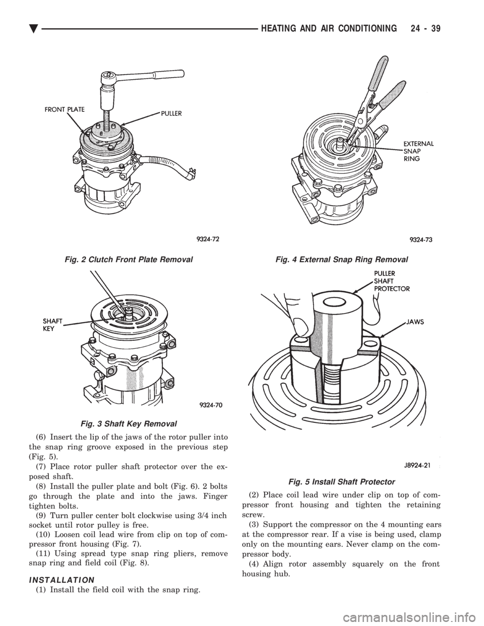
(6) Insert the lip of the jaws of the rotor puller into
the snap ring groove exposed in the previous step
(Fig. 5). (7) Place rotor puller shaft protector over the ex-
posed shaft. (8) Install the puller plate and bolt (Fig. 6). 2 bolts
go through the plate and into the jaws. Finger
tighten bolts. (9) Turn puller center bolt clockwise using 3/4 inch
socket until rotor pulley is free. (10) Loosen coil lead wire from clip on top of com-
pressor front housing (Fig. 7). (11) Using spread type snap ring pliers, remove
snap ring and field coil (Fig. 8).
INSTALLATION
(1) Install the field coil with the snap ring. (2) Place coil lead wire under clip on top of com-
pressor front housing and tighten the retaining
screw. (3) Support the compressor on the 4 mounting ears
at the compressor rear. If a vise is being used, clamp
only on the mounting ears. Never clamp on the com-
pressor body. (4) Align rotor assembly squarely on the front
housing hub.
Fig. 2 Clutch Front Plate Removal
Fig. 3 Shaft Key Removal
Fig. 4 External Snap Ring Removal
Fig. 5 Install Shaft Protector
Ä HEATING AND AIR CONDITIONING 24 - 39