1993 CHEVROLET PLYMOUTH ACCLAIM cooling
[x] Cancel search: coolingPage 1888 of 2438
to low. The number of notches determine the amount of
pulses. If available, an oscilloscope can display the
square wave patterns of each timing events. Top dead center (TDC) does not occur when notches
on the camshaft sprocket pass below the cylinder. TDC
occurs after the camshaft pulse (or pulses) and after
the 4 crankshaft pulses associated with the particular
cylinder. The arrows and cylinder call outs on Figure 4
represent which cylinder the flat spot and notches
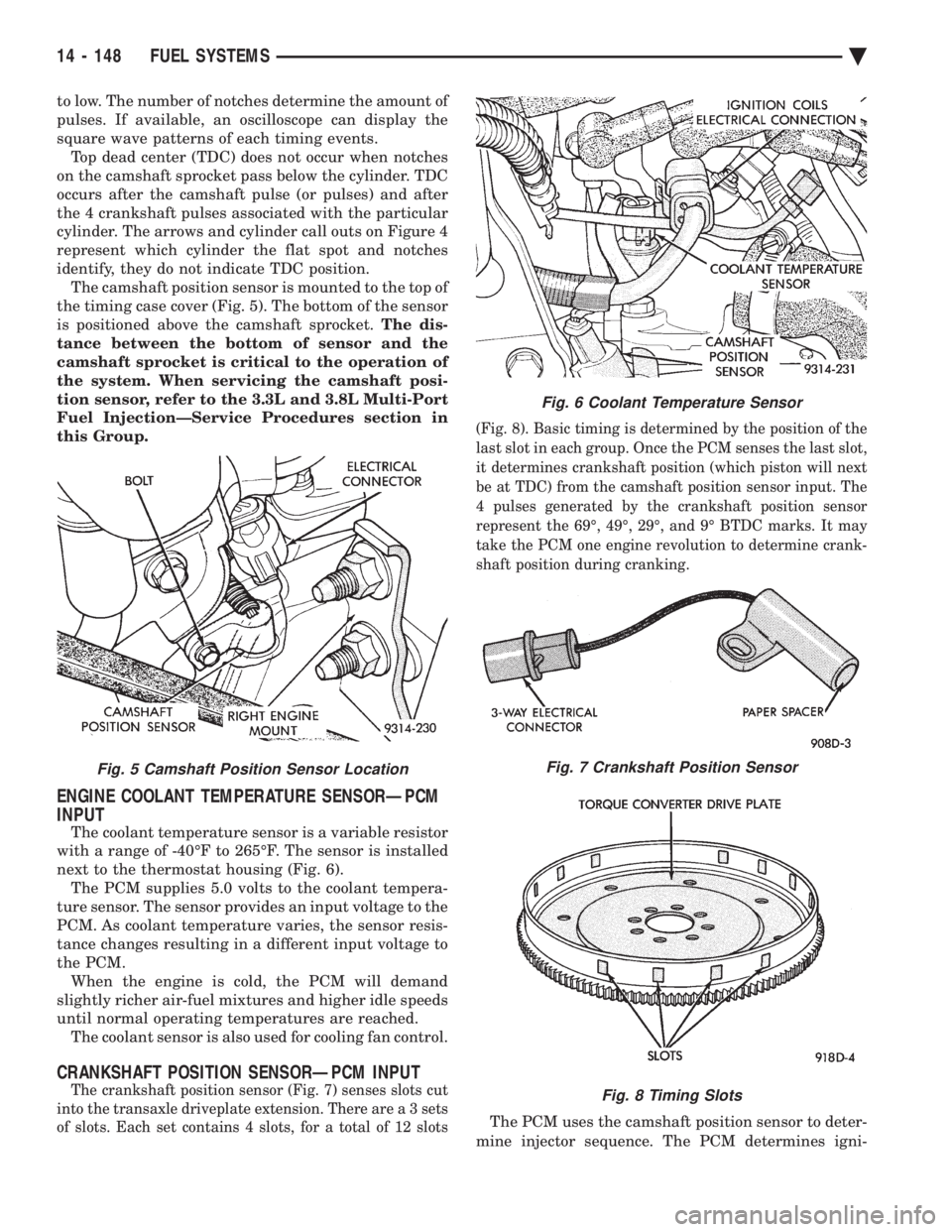
identify, they do not indicate TDC position. The camshaft position sensor is mounted to the top of
the timing case cover (Fig. 5). The bottom of the sensor
is positioned above the camshaft sprocket. The dis-
tance between the bottom of sensor and the
camshaft sprocket is critical to the operation of
the system. When servicing the camshaft posi-
tion sensor, refer to the 3.3L and 3.8L Multi-Port
Fuel InjectionÐService Procedures section in
this Group.
ENGINE COOLANT TEMPERATURE SENSORÐPCM
INPUT
The coolant temperature sensor is a variable resistor
with a range of -40ÉF to 265ÉF. The sensor is installed
next to the thermostat housing (Fig. 6). The PCM supplies 5.0 volts to the coolant tempera-
ture sensor. The sensor provides an input voltage to the
PCM. As coolant temperature varies, the sensor resis-
tance changes resulting in a different input voltage to
the PCM. When the engine is cold, the PCM will demand
slightly richer air-fuel mixtures and higher idle speeds
until normal operating temperatures are reached. The coolant sensor is also used for cooling fan control.
CRANKSHAFT POSITION SENSORÐPCM INPUT
The crankshaft position sensor (Fig. 7) senses slots cut
into the transaxle driveplate extension. There ar e a 3 sets
of slots. Each set contains 4 slots, for a total of 12 slots (Fig. 8). Basic timing is determined by the position of the
last slot in each group. Once the PCM senses the last slot,
it determines crankshaft position (which piston will next
be at TDC) from the camshaft position sensor input. The
4 pulses generated by the crankshaft position sensor
represent the 69É, 49É, 29É, and 9É BTDC marks. It may
take the PCM one engine revolution to determine crank-
shaft position during cranking.
The PCM uses the camshaft position sensor to deter-
mine injector sequence. The PCM determines igni-
Fig. 5 Camshaft Position Sensor Location
Fig. 6 Coolant Temperature Sensor
Fig. 7 Crankshaft Position Sensor
Fig. 8 Timing Slots
14 - 148 FUEL SYSTEMS Ä
Page 1932 of 2438
(10) Connect negative cable back on negative post
of battery. (11) Start engine and turn steering wheel several
times from stop to stop to bleed air from fluid in sys-
tem. Stop engine, check fluid level, and inspect sys-
tem for leaks. See Checking Fluid Level.
3.0 LITER
REMOVE
(1) REMOVE THE (-) NEGATIVE BATTERY CA-
BLE FROM THE BATTERY AND ISOLATE CA-
BLE. (2) Remove the serpentine accessory drive belt
from engine (Fig. 4). See Cooling, Group 7 for de-
tailed removal procedure.
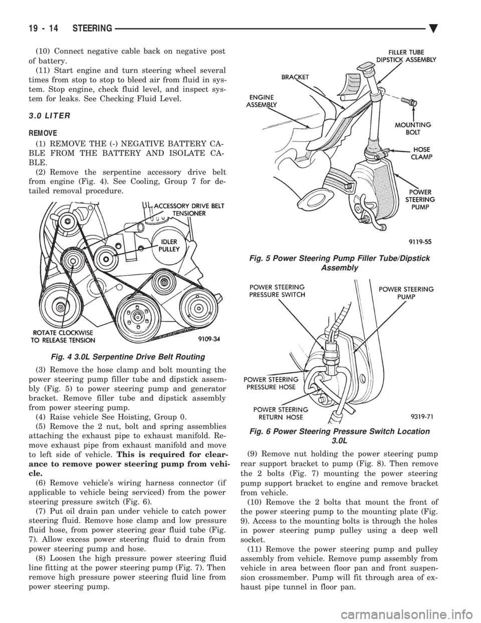
(3) Remove the hose clamp and bolt mounting the
power steering pump filler tube and dipstick assem-
bly (Fig. 5) to power steering pump and generator
bracket. Remove filler tube and dipstick assembly
from power steering pump. (4) Raise vehicle See Hoisting, Group 0.
(5) Remove the 2 nut, bolt and spring assemblies
attaching the exhaust pipe to exhaust manifold. Re-
move exhaust pipe from exhaust manifold and move
to left side of vehicle. This is required for clear-
ance to remove power steering pump from vehi-
cle. (6) Remove vehicle's wiring harness connector (if
applicable to vehicle being serviced) from the power
steering pressure switch (Fig. 6). (7) Put oil drain pan under vehicle to catch power
steering fluid. Remove hose clamp and low pressure
fluid hose, from power steering gear fluid tube (Fig.
7). Allow excess power steering fluid to drain from
power steering pump and hose. (8) Loosen the high pressure power steering fluid
line fitting at the power steering pump (Fig. 7). Then
remove high pressure power steering fluid line from
power steering pump. (9) Remove nut holding the power steering pump
rear support bracket to pump (Fig. 8). Then remove
the 2 bolts (Fig. 7) mounting the power steering
pump support bracket to engine and remove bracket
from vehicle. (10) Remove the 2 bolts that mount the front of
the power steering pump to the mounting plate (Fig.
9). Access to the mounting bolts is through the holes
in power steering pump pulley using a deep well
socket. (11) Remove the power steering pump and pulley
assembly from vehicle. Remove pump assembly from
vehicle in area between floor pan and front suspen-
sion crossmember. Pump will fit through area of ex-
haust pipe tunnel in floor pan.
Fig. 4 3.0L Serpentine Drive Belt Routing
Fig. 5 Power Steering Pump Filler Tube/Dipstick Assembly
Fig. 6 Power Steering Pressure Switch Location 3.0L
19 - 14 STEERING Ä
Page 1933 of 2438
(12) Transfer Required parts to the new power
steering pump assembly before installing in vehicle.
INSTALL
(1) Install the power steering pump assembly back
in vehicle in reverse order of removal. (2) Hold power steering pump against mounting
plate. Align power steering pump mounting holes
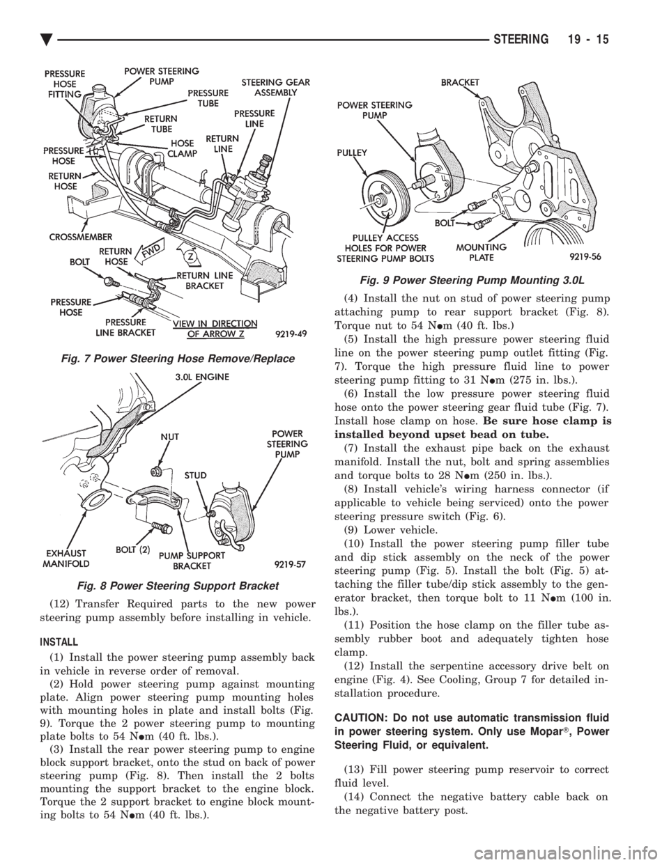
with mounting holes in plate and install bolts (Fig.
9). Torque the 2 power steering pump to mounting
plate bolts to 54 N Im (40 ft. lbs.).
(3) Install the rear power steering pump to engine
block support bracket, onto the stud on back of power
steering pump (Fig. 8). Then install the 2 bolts
mounting the support bracket to the engine block.
Torque the 2 support bracket to engine block mount-
ing bolts to 54 N Im (40 ft. lbs.). (4) Install the nut on stud of power steering pump
attaching pump to rear support bracket (Fig. 8).
Torque nut to 54 N Im (40 ft. lbs.)
(5) Install the high pressure power steering fluid
line on the power steering pump outlet fitting (Fig.
7). Torque the high pressure fluid line to power
steering pump fitting to 31 N Im (275 in. lbs.).
(6) Install the low pressure power steering fluid
hose onto the power steering gear fluid tube (Fig. 7).
Install hose clamp on hose. Be sure hose clamp is
installed beyond upset bead on tube. (7) Install the exhaust pipe back on the exhaust
manifold. Install the nut, bolt and spring assemblies
and torque bolts to 28 N Im (250 in. lbs.).
(8) Install vehicle's wiring harness connector (if
applicable to vehicle being serviced) onto the power
steering pressure switch (Fig. 6). (9) Lower vehicle.
(10) Install the power steering pump filler tube
and dip stick assembly on the neck of the power
steering pump (Fig. 5). Install the bolt (Fig. 5) at-
taching the filler tube/dip stick assembly to the gen-
erator bracket, then torque bolt to 11 N Im (100 in.
lbs.). (11) Position the hose clamp on the filler tube as-
sembly rubber boot and adequately tighten hose
clamp. (12) Install the serpentine accessory drive belt on
engine (Fig. 4). See Cooling, Group 7 for detailed in-
stallation procedure.
CAUTION: Do not use automatic transmission fluid
in power steering system. Only use Mopar T, Power
Steering Fluid, or equivalent.
(13) Fill power steering pump reservoir to correct
fluid level. (14) Connect the negative battery cable back on
the negative battery post.
Fig. 7 Power Steering Hose Remove/Replace
Fig. 8 Power Steering Support Bracket
Fig. 9 Power Steering Pump Mounting 3.0L
Ä STEERING 19 - 15
Page 1934 of 2438
(15) Start engine and turn steering wheel several
times from stop to stop to bleed air from fluid in sys-
tem. Stop engine, check fluid level, and inspect sys-
tem for leaks. See Checking Fluid Level.
3.3 & 3.8 LITER
REMOVE
(1) Remove the (-) negative battery cable from the
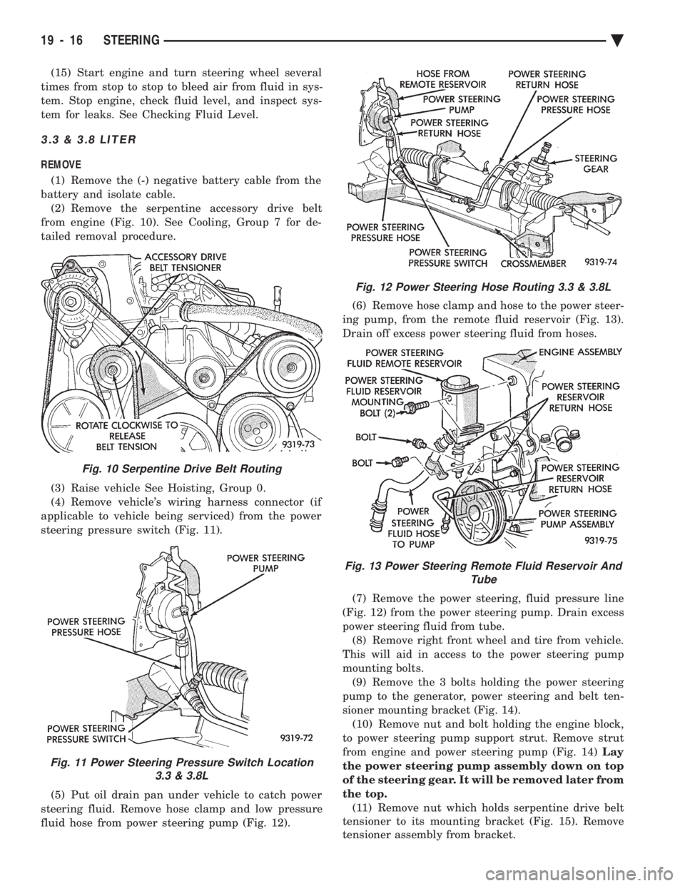
battery and isolate cable. (2) Remove the serpentine accessory drive belt
from engine (Fig. 10). See Cooling, Group 7 for de-
tailed removal procedure.
(3) Raise vehicle See Hoisting, Group 0.
(4) Remove vehicle's wiring harness connector (if
applicable to vehicle being serviced) from the power
steering pressure switch (Fig. 11).
(5) Put oil drain pan under vehicle to catch power
steering fluid. Remove hose clamp and low pressure
fluid hose from power steering pump (Fig. 12). (6) Remove hose clamp and hose to the power steer-
ing pump, from the remote fluid reservoir (Fig. 13).
Drain off excess power steering fluid from hoses.
(7) Remove the power steering, fluid pressure line
(Fig. 12) from the power steering pump. Drain excess
power steering fluid from tube. (8) Remove right front wheel and tire from vehicle.
This will aid in access to the power steering pump
mounting bolts. (9) Remove the 3 bolts holding the power steering
pump to the generator, power steering and belt ten-
sioner mounting bracket (Fig. 14). (10) Remove nut and bolt holding the engine block,
to power steering pump support strut. Remove strut
from engine and power steering pump (Fig. 14) Lay
the power steering pump assembly down on top
of the steering gear. It will be removed later from
the top. (11) Remove nut which holds serpentine drive belt
tensioner to its mounting bracket (Fig. 15). Remove
tensioner assembly from bracket.
Fig. 10 Serpentine Drive Belt Routing
Fig. 11 Power Steering Pressure Switch Location 3.3 & 3.8L
Fig. 12 Power Steering Hose Routing 3.3 & 3.8L
Fig. 13 Power Steering Remote Fluid Reservoir And Tube
19 - 16 STEERING Ä
Page 1937 of 2438
(18) Lower vehicle.
(19) Install the serpentine drive belt. Refer to (Fig.
10) for correct serpentine belt routing. See Cooling,
Group 7 for detailed installation procedure.
CAUTION: Do not use automatic transmission fluid
in power steering system. Only use Mopar T, Power
Steering Fluid, or equivalent.
(20) Fill power steering pump reservoir to correct
fluid level. (21) Connect the negative battery cable on the
negative battery post. (22) Start engine and turn steering wheel several
times from stop to stop to bleed air from fluid in sys-
tem. Stop engine, check fluid level, and inspect sys-
tem for leaks. See Checking Fluid Level.
TURBO III
REMOVE
(1) Disconnect the battery (-) negative cable from
the battery and isolate cable. (2) Raise vehicle See Hoisting, Group 0. Put oil
drain pan under vehicle to catch power steering
fluid. (3) Remove the right front underhood splash shield
for access to the serpentine belt tensioner. (4) Release the tension on the serpentine drive belt
tensioner and remove drive belt from power steering
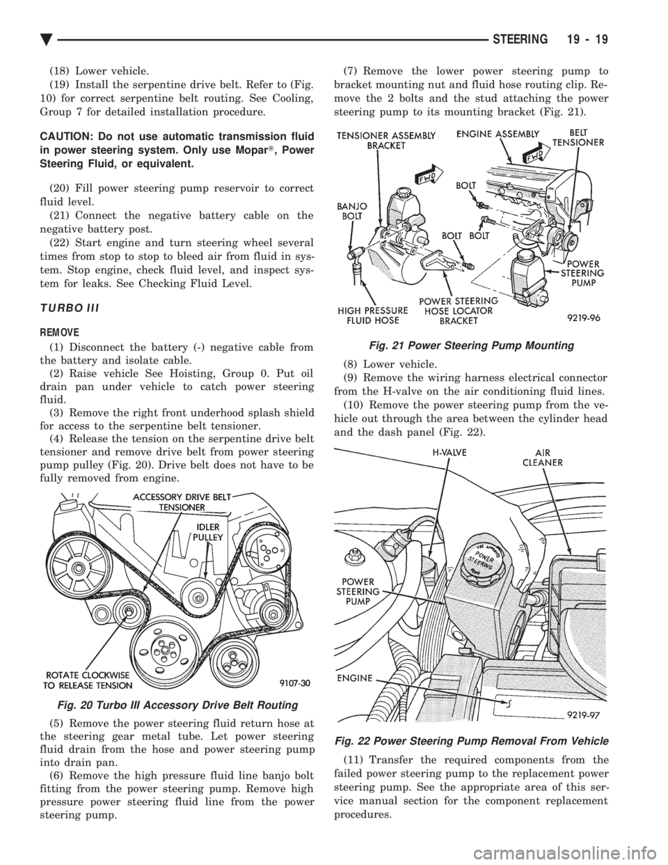
pump pulley (Fig. 20). Drive belt does not have to be
fully removed from engine.
(5) Remove the power steering fluid return hose at
the steering gear metal tube. Let power steering
fluid drain from the hose and power steering pump
into drain pan. (6) Remove the high pressure fluid line banjo bolt
fitting from the power steering pump. Remove high
pressure power steering fluid line from the power
steering pump. (7) Remove the lower power steering pump to
bracket mounting nut and fluid hose routing clip. Re-
move the 2 bolts and the stud attaching the power
steering pump to its mounting bracket (Fig. 21).
(8) Lower vehicle.
(9) Remove the wiring harness electrical connector
from the H-valve on the air conditioning fluid lines. (10) Remove the power steering pump from the ve-
hicle out through the area between the cylinder head
and the dash panel (Fig. 22).
(11) Transfer the required components from the
failed power steering pump to the replacement power
steering pump. See the appropriate area of this ser-
vice manual section for the component replacement
procedures.
Fig. 20 Turbo III Accessory Drive Belt Routing
Fig. 21 Power Steering Pump Mounting
Fig. 22 Power Steering Pump Removal From Vehicle
Ä STEERING 19 - 19
Page 1995 of 2438
THREE SPEED TORQUEFLITE AUTOMATIC TRANSAXLE INDEX
page page
Accumulator-Recondition ................... 67
Aluminum Thread Repair ................... 48
Assembly Subassembly Installation ........... 57
Band Adjustment ......................... 47
Bearing Adjustment Procedures .............. 81
Clutch and Servo Air Pressure Tests .......... 43
Differential Repair ........................ 76
Disassembly Subassembly Removal .......... 50
Fluid and Filter Change .................... 40
Fluid Drain and Refill ..................... 40
Fluid Leakage-Transaxle Torque Converter Housing Area .......................... 44
Fluid Level and Condition .................. 40
Front Clutch-Recondition ................... 62
Front Planetary & Annulus Gear-Recondition .... 65
Gearshift Linkage Adjustment ............... 46
General Information ....................... 35
Governor ............................... 48
Hydraulic Control Pressure Adjustments ....... 47
Hydraulic Pressure Tests ................... 42
Kickdown Servo (Controlled Load)-Recondition . . 67 Low/Reverse Servo-Recondition
.............. 66
Oil Cooler Flow Check .................... 48
Oil Coolers and Tubes Reverse Flushing ...... 48
Oil Pump-Recondition ..................... 62
Output Shaft Repair ...................... 71
Park/Neutral Position and Back-Up Lamp Switch . 47
Parking Pawl ............................ 71
Pump Oil Seal-Replacement ................ 61
Rear Clutch-Recondition ................... 64
Road Test .............................. 40
Selection of Lubricant ..................... 40
Special Additives ......................... 40
Three Speed Torqueflite General Diagnosis ..... 36
Throttle Pressure Linkage Adjustment ......... 46
Torque Converter Clutch Solenoid Wiring Connector ............................ 40
Transaxle and Torque Converter Removal ...... 48
Transfer Shaft Repair ..................... 68
Valve Body-Recondition .................... 57
Vehicle Speed Sensor Pinion Gear ........... 47
GENERAL INFORMATION
Safety goggles should be worn at all times
when working on these transaxles. This transaxle combines a fully automatic 3 speed
transmission, final drive gearing, and differential into
a front wheel drive system. The unit is a Metric
design. The identification markings and usage of the
transaxle are charted in Diagnosis and Tests. Transaxle operation requirements are differ-
ent for each vehicle and engine combination and
some internal parts will be different to provide
for this. Therefore, when replacing parts, refer to
the seven digit part number stamped on rear of
the transaxle oil pan flange. Within this transaxle, there are 3 primary areas:
(1) Main center line plus valve body.
(2) Transfer shaft center line (includes governor and
parking sprag). (3) Differential center line. Center distances be-
tween the main rotating parts in these 3 areas are held
precise. This maintains a low noise level through
smooth accurate mesh of the gears. The torque converter, transaxle area, and differential
are housed in an integral aluminum die casting. The
differential oil sump is common with thetransaxle
sump. Separate filling of the differential is NOT nec-
essary. The torque converter is attached to the crankshaft
through a flexible driving plate. Cooling of the con-
verter is accomplished by circulating the transaxle
fluid through an oil-to-water type cooler located in the
radiator side tank and/or an oil-to air heat ex- changer. The torque converter assembly is a sealed
unit that cannot be disassembled.
The transaxle fluid is filtered by an internal filter
attached to the lower side of the valve body assem-
bly. Engine torque is transmitted to the torque con-
verter then, through the input shaft to multiple-disc
clutches in the transaxle. The power flow depends on
the application of the clutches and bands. Refer to
Elements in Use Chart in Diagnosis and Tests sec-
tion. The transaxle consists of two multiple-disc
clutches, an overrunning clutch, two servos, a hy-
draulic accumulator, two bands, and two planetary
gear sets. They provide three forward ratios and a re-
verse ratio. The common sun gear of the planetary
gear sets is connected to the front clutch by a driving
shell. The drive shell is splined to the sun gear and
to the front clutch retainer. The hydraulic system
consists of an oil pump, and a single valve body
which contains all of the valves except the governor
valves. The transaxle sump and differential sump are
both vented through the dipstick.Output torque
from the main center line is delivered through heli-
cal gears to the transfer shaft.This gear set is a
factor of the final drive (axle) ratio. The shaft also
carries the governor and parking sprag. An integral
helical gear on the transfer shaft drives the differen-
tial ring gear. The final drive gearing is completed
with one of three gear sets producing overall top gear
ratios of 2.78, 3.02, or 3.22 depending on model and
application.
Ä TRANSAXLE 21 - 35
Page 2047 of 2438
OPERATION
The 41TE transaxle provides forward ratios of 2.84,
1.57, 1.00, and 0.69 with torque converter clutch
available in 2nd, direct, or overdrive gear; the Re-
verse ratio is 2.21. The shift lever is conventional
with six positions: P, R, N, OD, 3, and L. When OD
is selected the transaxle shifts normally through all
four speeds with torque converter clutch available in
overdrive; this position is recommended for most
driving. The 3 position is tailored for use in hilly or
mountainous driving. When 3 is selected, the trans-
mission uses only 1st, 2nd, and direct gears with
2nd-direct shift delayed to 40 mph or greater. When
operating in 3 or L positions torque converter clutch
application occurs in direct gear for improved trans-
mission cooling under heavy loads. If high engine
coolant temperature occurs, the torque converter
clutch will also engage in 2nd gear. The L position
provides maximum engine braking for descending
steep grades. Unlike most current transaxles, up-
shifts are provided to 2nd or direct gear at peak en-
gine speeds if the accelerator is depressed. This
provides engine over-speed protection and maximum
performance.
CLUTCH AND GEAR
The transaxle consists of:
² Three multiple disc input clutches
² Two multiple disc grounded clutches
² Four hydraulic accumulators
² Two planetary gear sets
This provides four forward ratios and a reverse ra-
tio. The clutch-apply pistons were designed with cen-
trifugally balanced oil cavities so that quick response
and good control can be achieved at any speed. A
push/pull piston is incorporated for two of the three
input clutches.
CAUTION: Some clutch packs appear similar, but
they are not the same. Do not interchange clutch
components as they might fail.
HYDRAULICS
The hydraulics of the transaxle provide the manual
shift lever select function, main line pressure regula-
tion, and torque converter and cooler flow control.
Oil flow to the friction elements is controlled directly
by four solenoid valves. The hydraulics also include a
unique logic-controlled ``solenoid torque converter
clutch control valve''. This valve locks out the 1st
gear reaction element with the application of 2nd, di-
rect, or overdrive gear elements. It also redirects the
1st gear solenoid output so that it can control torque
converter clutch operation. To regain access to 1st
gear, a special sequence of solenoid commands must
be used to unlock and move the solenoid torque con-
verter clutch control valve. This precludes any appli- cation of the 1st gear reaction element with other
elements applied. It also allows one solenoid to con-
trol two friction elements.
Small, high-rate accumulators are provided in each
controlled friction element circuit. These serve to ab-
sorb the pressure responses, and allow the controls to
read and respond to changes that are occurring.
SOLENOIDS
Since the solenoid valves perform virtually all con-
trol functions, these valves must be extremely dura-
ble and tolerant of normal dirt particles. For that
reason hardened-steel poppet and ball valves are
used. These are free from any close operating clear-
ances, and the solenoids operate the valves directly
without any intermediate element. Direct operation
means that these units must have very high output
so that they can close against the sizeable flow areas
and high line pressures. Fast response is also re-
quired to meet the control requirements. Two of the solenoids are normally-venting and two
are normally-applying; this was done to provide a de-
fault mode of operation. With no electrical power, the
transmission provides 2nd gear in OD, 3,orLshift
lever positions. All other transmission lever positions
will operate normally. The choice of 2nd gear was
made to provide adequate breakaway performance
while still accommodating highway speeds.
SENSORS
There are three pressure switches to identify sole-
noid application and two speed sensors to read input
(torque converter turbine) and output (parking sprag)
speeds. There is also a position switch to indicate the
manual shift lever position. The pressure switches
are incorporated in an assembly with the solenoids.
Engine speed, throttle position, temperature, etc., are
also observed. Some of these signals are read directly
from the engine control sensors; others are read from
a multiplex circuit with the powertrain control mod-
ule.
ELECTRONICS
The 41TE transmission control module is located
underhood in a potted, die-cast aluminum housing
with a sealed, 60-way connector.
ELECTRONIC MODULATED CONVERTER CLUTCH (EMCC)
The EMCC enables the torque converter clutch to
partially engage between 23 to 47 MPH before full
engagement at about 50 MPH and beyond. This fea-
ture is on all vehicles equipped with the 41TE tran-
saxle.
ADAPTIVE CONTROLS
These controls function by reading the input and
output speeds over 140 times a second and respond-
Ä TRANSAXLE 21 - 87
Page 2059 of 2438
CAUTION: If the vehicle is equipped with two oil
coolers (one in the radiator tank, one in front of the
radiator) they must be flushed separately. Do not
attempt to flush both coolers at one time. (1) Disconnect the cooler lines at the transmission.
(2) Using a hand suction gun filled with mineral
spirits, reverse flush the cooler. Force mineral spirits
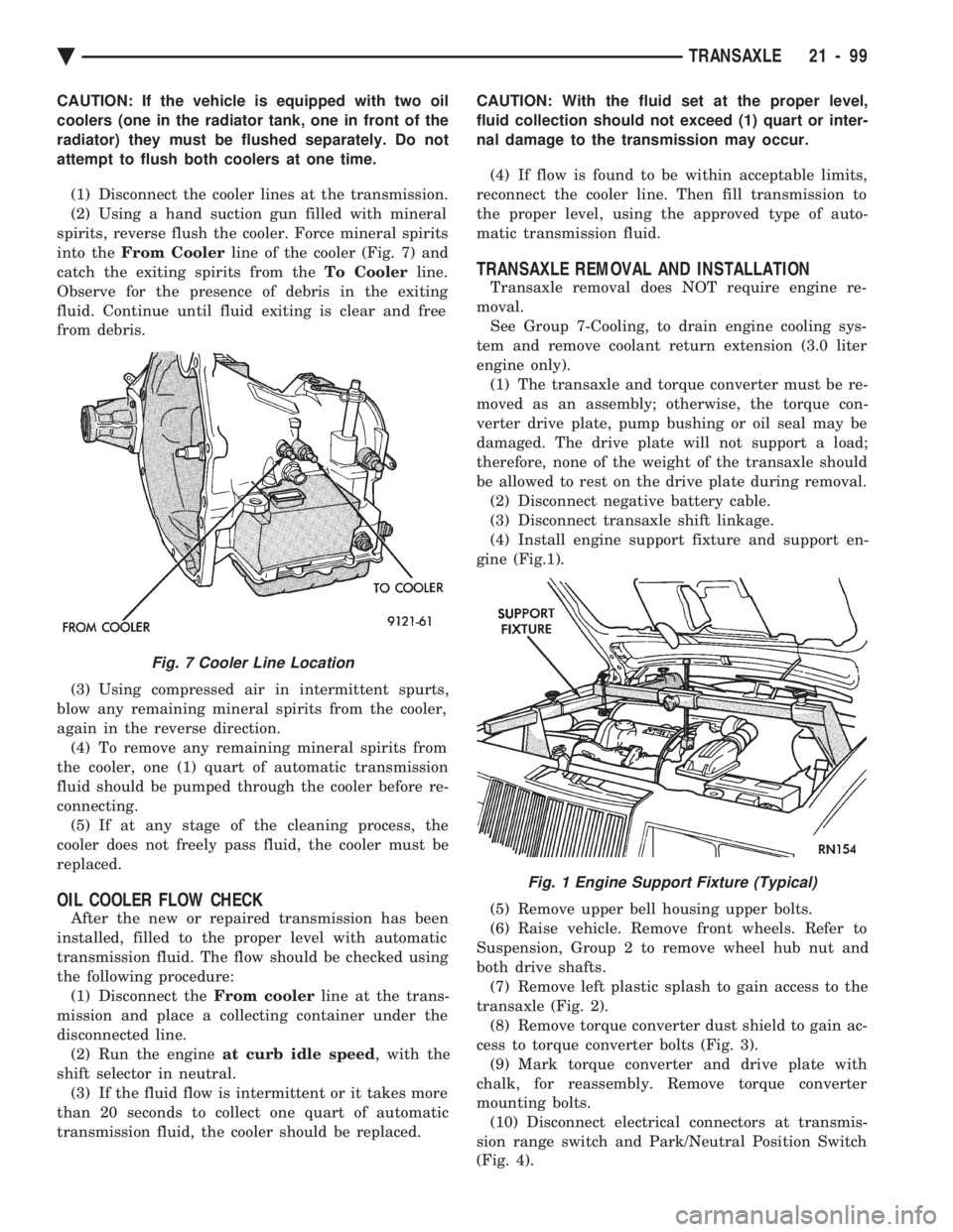
into the From Cooler line of the cooler (Fig. 7) and
catch the exiting spirits from the To Coolerline.
Observe for the presence of debris in the exiting
fluid. Continue until fluid exiting is clear and free
from debris.
(3) Using compressed air in intermittent spurts,
blow any remaining mineral spirits from the cooler,
again in the reverse direction. (4) To remove any remaining mineral spirits from
the cooler, one (1) quart of automatic transmission
fluid should be pumped through the cooler before re-
connecting. (5) If at any stage of the cleaning process, the
cooler does not freely pass fluid, the cooler must be
replaced.
OIL COOLER FLOW CHECK
After the new or repaired transmission has been
installed, filled to the proper level with automatic
transmission fluid. The flow should be checked using
the following procedure: (1) Disconnect the From coolerline at the trans-
mission and place a collecting container under the
disconnected line. (2) Run the engine at curb idle speed , with the
shift selector in neutral. (3) If the fluid flow is intermittent or it takes more
than 20 seconds to collect one quart of automatic
transmission fluid, the cooler should be replaced. CAUTION: With the fluid set at the proper level,
fluid collection should not exceed (1) quart or inter-
nal damage to the transmission may occur.
(4) If flow is found to be within acceptable limits,
reconnect the cooler line. Then fill transmission to
the proper level, using the approved type of auto-
matic transmission fluid.
TRANSAXLE REMOVAL AND INSTALLATION
Transaxle removal does NOT require engine re-
moval. See Group 7-Cooling, to drain engine cooling sys-
tem and remove coolant return extension (3.0 liter
engine only). (1) The transaxle and torque converter must be re-
moved as an assembly; otherwise, the torque con-
verter drive plate, pump bushing or oil seal may be
damaged. The drive plate will not support a load;
therefore, none of the weight of the transaxle should
be allowed to rest on the drive plate during removal. (2) Disconnect negative battery cable.
(3) Disconnect transaxle shift linkage.
(4) Install engine support fixture and support en-
gine (Fig.1).
(5) Remove upper bell housing upper bolts.
(6) Raise vehicle. Remove front wheels. Refer to
Suspension, Group 2 to remove wheel hub nut and
both drive shafts. (7) Remove left plastic splash to gain access to the
transaxle (Fig. 2). (8) Remove torque converter dust shield to gain ac-
cess to torque converter bolts (Fig. 3). (9) Mark torque converter and drive plate with
chalk, for reassembly. Remove torque converter
mounting bolts. (10) Disconnect electrical connectors at transmis-
sion range switch and Park/Neutral Position Switch
(Fig. 4).
Fig. 7 Cooler Line Location
Fig. 1 Engine Support Fixture (Typical)
Ä TRANSAXLE 21 - 99