1993 CHEVROLET DYNASTY service
[x] Cancel search: servicePage 2373 of 2438
To install, reverse the preceding operation.
BLEND-AIR DOOR ACTUATOR
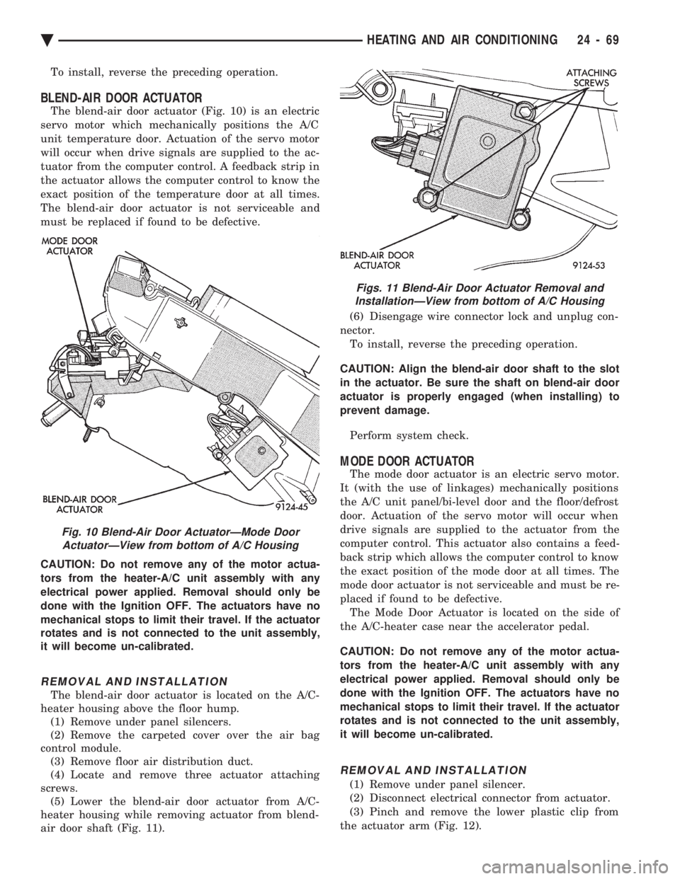
The blend-air door actuator (Fig. 10) is an electric
servo motor which mechanically positions the A/C
unit temperature door. Actuation of the servo motor
will occur when drive signals are supplied to the ac-
tuator from the computer control. A feedback strip in
the actuator allows the computer control to know the
exact position of the temperature door at all times.
The blend-air door actuator is not serviceable and
must be replaced if found to be defective.
CAUTION: Do not remove any of the motor actua-
tors from the heater-A/C unit assembly with any
electrical power applied. Removal should only be
done with the Ignition OFF. The actuators have no
mechanical stops to limit their travel. If the actuator
rotates and is not connected to the unit assembly,
it will become un-calibrated.
REMOVAL AND INSTALLATION
The blend-air door actuator is located on the A/C-
heater housing above the floor hump. (1) Remove under panel silencers.
(2) Remove the carpeted cover over the air bag
control module. (3) Remove floor air distribution duct.
(4) Locate and remove three actuator attaching
screws. (5) Lower the blend-air door actuator from A/C-
heater housing while removing actuator from blend-
air door shaft (Fig. 11). (6) Disengage wire connector lock and unplug con-
nector. To install, reverse the preceding operation.
CAUTION: Align the blend-air door shaft to the slot
in the actuator. Be sure the shaft on blend-air door
actuator is properly engaged (when installing) to
prevent damage.
Perform system check.
MODE DOOR ACTUATOR
The mode door actuator is an electric servo motor.
It (with the use of linkages) mechanically positions
the A/C unit panel/bi-level door and the floor/defrost
door. Actuation of the servo motor will occur when
drive signals are supplied to the actuator from the
computer control. This actuator also contains a feed-
back strip which allows the computer control to know
the exact position of the mode door at all times. The
mode door actuator is not serviceable and must be re-
placed if found to be defective. The Mode Door Actuator is located on the side of
the A/C-heater case near the accelerator pedal.
CAUTION: Do not remove any of the motor actua-
tors from the heater-A/C unit assembly with any
electrical power applied. Removal should only be
done with the Ignition OFF. The actuators have no
mechanical stops to limit their travel. If the actuator
rotates and is not connected to the unit assembly,
it will become un-calibrated.
REMOVAL AND INSTALLATION
(1) Remove under panel silencer.
(2) Disconnect electrical connector from actuator.
(3) Pinch and remove the lower plastic clip from
the actuator arm (Fig. 12).
Fig. 10 Blend-Air Door ActuatorÐMode Door ActuatorÐView from bottom of A/C Housing
Figs. 11 Blend-Air Door Actuator Removal andInstallationÐView from bottom of A/C Housing
Ä HEATING AND AIR CONDITIONING 24 - 69
Page 2374 of 2438
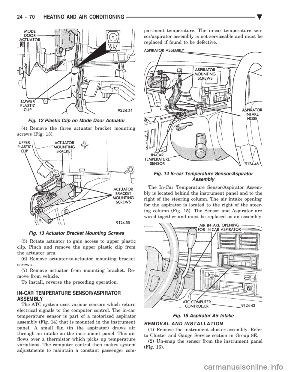
(4) Remove the three actuator bracket mounting
screws (Fig. 13).
(5) Rotate actuator to gain access to upper plastic
clip. Pinch and remove the upper plastic clip from
the actuator arm. (6) Remove actuator-to-actuator mounting bracket
screws. (7) Remove actuator from mounting bracket. Re-
move from vehicle. To install, reverse the preceding operation.
IN-CAR TEMPERATURE SENSOR/ASPIRATOR
ASSEMBLY
The ATC system uses various sensors which return
electrical signals to the computer control. The in-car
temperature sensor is part of a motorized aspirator
assembly (Fig. 14) that is mounted in the instrument
panel. A small fan (in the aspirator) draws air
through an intake on the instrument panel. This air
flows over a thermistor which picks up temperature
variations. The computer control then makes system
adjustments to maintain a constant passenger com- partment temperature. The in-car temperature sen-
sor/aspirator assembly is not serviceable and must be
replaced if found to be defective.
The In-Car Temperature Sensor/Aspirator Assem-
bly is located behind the instrument panel and to the
right of the steering column. The air intake opening
for the aspirator is located to the right of the steer-
ing column (Fig. 15). The Sensor and Aspirator are
wired together and must be replaced as an assembly.
REMOVAL AND INSTALLATION
(1) Remove the instrument cluster assembly. Refer
to Cluster and Gauge Service section in Group 8E. (2) Un-snap the sensor from the instrument panel
(Fig. 16).
Fig. 12 Plastic Clip on Mode Door Actuator
Fig. 13 Actuator Bracket Mounting Screws
Fig. 14 In-car Temperature Sensor/Aspirator Assembly
Fig. 15 Aspirator Air Intake
24 - 70 HEATING AND AIR CONDITIONING Ä
Page 2375 of 2438
(3) Remove the two aspirator mounting screws.
(4) Disconnect the aspirator intake hose from the
instrument panel. (5) Remove sensor/aspirator and it's wiring har-
ness from vehicle. To install, reverse the preceding operation.
WATER TEMPERATURE SENSOR
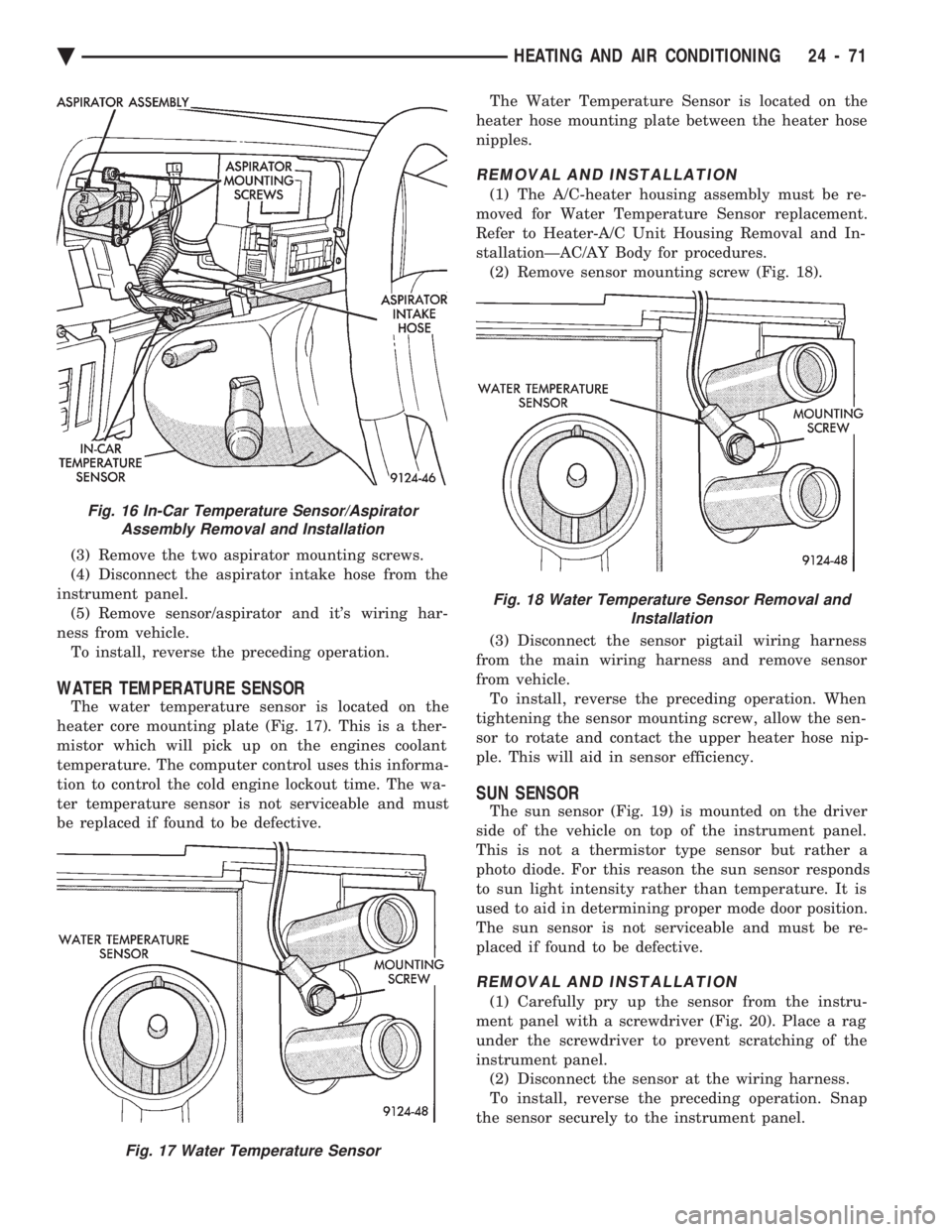
The water temperature sensor is located on the
heater core mounting plate (Fig. 17). This is a ther-
mistor which will pick up on the engines coolant
temperature. The computer control uses this informa-
tion to control the cold engine lockout time. The wa-
ter temperature sensor is not serviceable and must
be replaced if found to be defective. The Water Temperature Sensor is located on the
heater hose mounting plate between the heater hose
nipples.
REMOVAL AND INSTALLATION
(1) The A/C-heater housing assembly must be re-
moved for Water Temperature Sensor replacement.
Refer to Heater-A/C Unit Housing Removal and In-
stallationÐAC/AY Body for procedures. (2) Remove sensor mounting screw (Fig. 18).
(3) Disconnect the sensor pigtail wiring harness
from the main wiring harness and remove sensor
from vehicle. To install, reverse the preceding operation. When
tightening the sensor mounting screw, allow the sen-
sor to rotate and contact the upper heater hose nip-
ple. This will aid in sensor efficiency.
SUN SENSOR
The sun sensor (Fig. 19) is mounted on the driver
side of the vehicle on top of the instrument panel.
This is not a thermistor type sensor but rather a
photo diode. For this reason the sun sensor responds
to sun light intensity rather than temperature. It is
used to aid in determining proper mode door position.
The sun sensor is not serviceable and must be re-
placed if found to be defective.
REMOVAL AND INSTALLATION
(1) Carefully pry up the sensor from the instru-
ment panel with a screwdriver (Fig. 20). Place a rag
under the screwdriver to prevent scratching of the
instrument panel. (2) Disconnect the sensor at the wiring harness.
To install, reverse the preceding operation. Snap
the sensor securely to the instrument panel.
Fig. 16 In-Car Temperature Sensor/Aspirator Assembly Removal and Installation
Fig. 17 Water Temperature Sensor
Fig. 18 Water Temperature Sensor Removal and Installation
Ä HEATING AND AIR CONDITIONING 24 - 71
Page 2378 of 2438
Involves the wiring, blend-air door actuator, or the
ATC control head.
² DIAGNOSTIC TROUBLE CODES 3, 16, 17, 18, 19,
and 24 Involves the wiring, mode door actuator, or the ATC
control head.
² DIAGNOSTIC TROUBLE CODE 4
Involves the wiring, blend-air door actuator, mode
door actuator, fresh/recirc. door actuator, or the ATC
control head.
² DIAGNOSTIC TROUBLE CODE 5
Involves the wiring, fresh/recirc. door actuator, or the
ATC control head.
² DIAGNOSTIC TROUBLE CODE 6
Involves the compressor circuit signal wiring, or the
ATC control head.
² DIAGNOSTIC TROUBLE CODE 7
Involves the blower wiring, power module, or the
ATC control head.
² DIAGNOSTIC TROUBLE CODES 8, 21, 22
Requires replacing the ATC control head.
² DIAGNOSTIC TROUBLE CODES 9, and 27
Involves the wiring, sun sensor, or the ATC control
head.
² DIAGNOSTIC TROUBLE CODES 10, and 28
Involves the wiring, water temperature sensor, or the
ATC control head.
² DIAGNOSTIC TROUBLE CODES 11, and 25
Involves the wiring, ambient temperature sensor, or
the ATC control head.
² DIAGNOSTIC TROUBLE CODES 12, and 26
Involves the wiring, in-car temperature
sensor/aspirator, or the ATC control head.
DIAGNOSTIC TROUBLE CODE SERVICE PROCE-
DURES
The control keyboard will not function if pins
7, 9, 17, 19, or 20 of the 21-way wiring connector
are shorted to battery voltage. For electrical pin numbers, refer to the wiring Pin
out charts (Figs. 1, 2, 3, 4, 5, or 6).
DIAGNOSTIC TROUBLE CODE 1ÐOUTPUT FAILURE WITH ALL OUTPUTS LOW
(1) Remove pin #2 from 21-way connector on control
and retest system. If code 01 does not appear, the
control is good. Disconnect 21-way connector from control. With an
ohmmeter, measure the resistance between pin #2 and
pin #12 of 21-way. This should be between 2,600 and
2,800 ohms. If yes, the power module is good. Source of voltage on pin #2 is in the wiring. Repair
and retest system. (2) Remove pin #13 from 21-way connector on con-
trol and retest system. If code 01 does not appear, the
control is good. Locate source of voltage on pin #13.
Repair and retest system. (3) Remove pin #5 from 21-way connector on control
and retest system. If code 01 does not appear, the
control is good. Locate source of voltage on pin #5.
Repair and retest system. (4) Remove pin #6 from 21-way connector on control
and retest system. If code 01 does not appear, the
control is good. Locate source of voltage on pin #6.
Repair and retest system. (5) Remove pin #15 from 21-way connector on con-
trol and retest system. If code 01 does not appear, the
control is good. Locate source of voltage on pin #15.
Repair and retest system.
DIAGNOSTIC TROUBLE CODE 2ÐBLEND AC- TUATOR DRIVE SIGNAL NOT HIGH
If both Diagnostic Trouble Codes 2 and 3 occur
simultaneously, do both procedures. There is
typically only 1 failure. (1) Disconnect terminal #6 on the ATC control 21-
way connector and retest the system. Note that remov-
ing this terminal may generate additional Diagnostic
Trouble Codes. Disregard these at this time. (2) If Diagnostic Trouble Code 2 reappears, replace
control. (3) If code 2 does not reappear, the problem is a
shorted blend door actuator motor or a short to ground
in circuit 33 (pin #6). (4) Remove 21-way connector and check for continu-
ity from pin #6 to chassis ground. There should not be
any continuity. If continuity is there, repair wiring and
retest. (5) Check resistance across pins #6 and #4 of the
21-way for a shorted actuator motor. Resistance should
be between 20 and 50 ohms. If not correct, replace
actuator.
DIAGNOSTIC TROUBLE CODE 3ÐMODE AC- TUATOR DRIVE SIGNAL NOT HIGH
If both Diagnostic Trouble Codes 2 and 3 occur
simultaneously, do both procedures. There is
typically only 1 failure. (1) Disconnect terminal #5 on the ATC control 21-
way connector and retest the system. Removing this
terminal may generate additional Diagnostic Trouble
Codes. Disregard these at this time. (2) If Diagnostic Trouble Code 3 reappears, replace
control. (3) If code 3 does not reappear, the problem is a
shorted mode door actuator motor, or a short to ground
in circuit #35 (pin #5). (4) Remove 21-way and check for continuity from pin
#5 to chassis ground. There should not be any continu-
ity. If continuity is there, repair wiring and retest.
24 - 74 HEATING AND AIR CONDITIONING Ä
Page 2384 of 2438
(4) If pin #13 shows continuity, repair circuit C02
and retest. (5) If no continuity is shown, replace the ATC con-
trol and retest.
DIAGNOSTIC TROUBLE CODE 7ÐBLOWER DRIVE SIGNAL NOT HIGH
First check the 4-way connector to the power
module for correct installation (1) With the ignition ON, check for ignition volt-
age to the power module pin #1 from the ATC con-
trol. If ignition is present at the power module,
proceed to step 3. If not proceed to step 2. (2) With the 21-way connector still connected and
the ignition ON, check for power module ignition
feed at the control pin #12. If ignition is not present,
replace the control. If ignition voltage is present, re-
pair the open in the wire between the control pin
#12 and power module pin #1. Retest system. (3) Turn ignition OFF and disconnect the 21-way
connector. Measure the resistance between pins #2
and #12. The resistance should read between 2,600
and 2,800 ohms. If correct, replace the ATC control.
If not correct, proceed to step 4. (4) Remove the 4-way connector from the power
module. Check for continuity between the ATC con-
trol pin #2 and power module pin #2. If no continu-
ity is shown, repair the wire for an open. If
continuity is shown, replace the power module and
retest.
DIAGNOSTIC TROUBLE CODE 8ÐA/D CONVERTOR INTERNAL FAILURE
Diagnostics will indicate a Diagnostic Trouble Code
8 if the internal reference voltage of the A/D Conver-
tor is not correct. This Diagnostic Trouble Code is
not serviceable. If a Diagnostic Trouble Code 8 oc-
curs, the computer control head must be replaced.
DIAGNOSTIC TROUBLE CODE 9ÐSUN LOAD SENSOR FAILURE
(1) Unplug the 21-way connector from the control
and check pin #19 for continuity to chassis ground.
If continuity is present, repair the wire shorted to
ground. If no continuity is present, proceed to step 2. (2) Plug the 21-way connector back in. Remove pin
#19 from the 21 way connector and run diagnostics
again. If Diagnostic Trouble Code 9 is still present,
replace the control. If code 9 is not present, replace
the sun sensor.
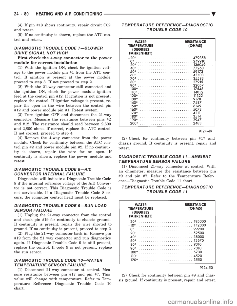
DIAGNOSTIC TROUBLE CODE 10ÐWATER TEMPERATURE SENSOR FAILURE
(1) Disconnect 21-way connector at control. Mea-
sure resistance between pin #17 and pin #7. This
value will change with temperature. Refer to Tem-
perature ReferenceÐDiagnostic Trouble Code 10
chart. (2) Check for continuity between pin #17 and
chassis ground. If continuity is present, repair and
retest.
DIAGNOSTIC TROUBLE CODE 11ÐAMBIENT TEMPERATURE SENSOR FAILURE
(1) Disconnect 21-way connector at control. With
an ohmmeter, measure the resistance between pin
#9 and pin #7. Refer to the Temperature Refer-
enceÐDiagnostic Trouble Code 11 chart.
(2) Check for continuity between pin #9 and chas-
sis ground. If continuity is present, repair and retest.
TEMPERATURE REFERENCEÐDIAGNOSTIC TROUBLE CODE 10
TEMPERATURE REFERENCEÐDIAGNOSTICTROUBLE CODE 11
24 - 80 HEATING AND AIR CONDITIONING Ä
Page 2386 of 2438
of the 5-way connector. If continuity is not present,
repair circuit for an open. If present, continue to step
4.(4) Install 5-way connector back into the mode
door actuator. Then check for continuity between
pins #7 and #16 of the 21-way connector. If continu-
ity is present, replace the ATC control. If continuity
is not present, replace the mode door actuator.
DIAGNOSTIC TROUBLE CODE 19ÐMODE DOOR FEEDBACK SHORTED TO GROUND
(1) Remove the 21-way connector from the control,
and the 5 way connector from the mode door actua-
tor. (2) Check for continuity between pin #16 of the
21-way connector and chassis ground. If present, re-
pair circuit for short to ground. If not present, con-
tinue to step 3. (3) Plug in the 5-way connector and measure resis-
tance between pins #7 and #16 of the 21-way con-
nector. If the resistance is less than 10 ohms, replace
the actuator. If not, replace the control head.
DIAGNOSTIC TROUBLE CODE 20ÐBLEND DOOR MOVED DURING MODE DOOR TEST
(1) Remove the 21-way connector from the control
and the 5-way connector from the three actuators. (2) Check for continuity between pin #4 of the 21-
way connector and pin #4 of each actuator. If conti-
nuity is not present for a particular actuator circuit,
repair that circuit and retest system. If continuity is
present for all circuits, continue to step 3. (3) Plug in the 5-way connectors and check for re-
sistance between pins #4 and #6 of the 21-way con-
nector for the blend air actuator. Then check pins #4
and #5 of the 21-way connector for the mode actua-
tor. The resistance should be between 20-50 ohms. If
either of the actuators do not pass the resistance
tests, replace that particular actuator and retest the
system. If both pass the resistance test, replace the
ATC control.
DIAGNOSTIC TROUBLE CODE 21ÐROM CHECK SUM ERROR
During the Diagnostics test, the computer will ver-
ify it's own internal program. If it finds any part to
be bad, a Diagnostic Trouble Code 21 will be set.
This Diagnostic Trouble Code is not serviceable. If a
Fail Code 21 occurs, the ATC Control Module must
be replaced.
DIAGNOSTIC TROUBLE CODE 22ÐCOMPUTER ERROR
If incorrect data is found in the ATC Control com-
puter module, a Diagnostic Trouble Code 22 will be
set. This Fail Code is not serviceable. If a Diagnostic
Trouble Code 22 occurs, the ATC Control Module
must be replaced.
DIAGNOSTIC TROUBLE CODE 23ÐBLEND
DOOR FEEDBACK FAILED
This Diagnostic Trouble Code is set during normal
ATC operation. The Diagnostic Trouble Code will be
set only after the ATC control has been operating for
15 minutes. The control will compensate for the feed-
back failure immediately upon power up, but the Di-
agnostic Trouble Code will not be set until the time
limit has been met. Diagnostic Trouble Code 23 will be stored within
the ATC Control, and must be cleared after the fail-
ure has been repaired. To clear this Diagnostic Trou-
ble Code, refer to Erasing Diagnostic Trouble Codes
23 through 28 from ATC Control. Follow service procedures for Diagnostic Trouble
Codes 14 and 15 when repairing.
DIAGNOSTIC TROUBLE CODE 24ÐMODE DOOR FEEDBACK FAILED
This Diagnostic Trouble Code is set during normal
ATC operation. The Diagnostic Trouble Code will be
set only after the ATC control has been operating for
15 minutes. The control will compensate for the feed-
back failure immediately upon power up, but the Di-
agnostic Trouble Code will not be set until the time
limit has been met. Diagnostic Trouble Code 24 will be stored within
the ATC Control, and must be cleared after the fail-
ure has been repaired. To clear this Diagnostic Trou-
ble Code, refer to Erasing Diagnostic Trouble Codes
23 through 28 From ATC Control. Follow service procedures for Diagnostic Trouble
Codes 18 and 19 when repairing.
DIAGNOSTIC TROUBLE CODE 25ÐAMBIENT TEMPERATURE SENSOR FAILURE
This Diagnostic Trouble Code is set during normal
ATC operation. The Diagnostic Trouble Code will be
set only after the ATC control has been operating for
15 minutes. The control will compensate for the feed-
back failure immediately upon power up, but the Di-
agnostic Trouble Code will not be set until the time
limit has been met. Diagnostic Trouble Code 25 will be stored within
the ATC Control, and must be cleared after the fail-
ure has been repaired. To clear this Diagnostic Trou-
ble Code, refer to Erasing Diagnostic Trouble Codes
23 through 28 from ATC Control. Follow service procedures for Diagnostic Trouble
Code 11 when repairing.
DIAGNOSTIC TROUBLE CODE 26ÐIN-CAR TEMPERATURE SENSOR/ASPIRATOR FAILED
This Diagnostic Trouble Code is set during normal
ATC operation. The Diagnostic Trouble Code will be
set only after the ATC control has been operating for
15 minutes. The control will compensate for the feed-
24 - 82 HEATING AND AIR CONDITIONING Ä
Page 2387 of 2438
back failure immediately upon power up, but the Di-
agnostic Trouble Code will not be set until the time
limit has been met. Diagnostic Trouble Code 26 will be stored within
the ATC Control, and must be cleared after the fail-
ure has been repaired. To clear this Diagnostic Trou-
ble Code, refer to Erasing Diagnostic Trouble Codes
23 through 28 from ATC Control. Follow service procedures for Diagnostic Trouble
Code 12 when repairing.
DIAGNOSTIC TROUBLE CODE 27ÐSUN LOAD SENSOR FAILED
This Diagnostic Trouble Code is set during normal
ATC operation. The Diagnostic Trouble Code will be
set only after the ATC control has been operating for
15 minutes. The control will compensate for the feed-
back failure immediately upon power up, but the Di-
agnostic Trouble Code will not be set until the time
limit has been met. Diagnostic Trouble Code 27 will be stored within
the ATC Control, and must be cleared after the fail-
ure has been repaired. To clear this Diagnostic Trou-
ble Code, refer to Erasing Diagnostic Trouble Codes
23 through 28 from ATC Control. Follow service procedures for Diagnostic Trouble
Code 12 when repairing.
DIAGNOSTIC TROUBLE CODE 28ÐWATER TEMPERATURE SENSOR FAILED
This Diagnostic Trouble Code is set during normal
ATC operation. The Diagnostic Trouble Code will be
set only after the ATC control has been operating for
15 minutes. The control will compensate for the feed-
back failure immediately upon power up, but the Di-
agnostic Trouble Code will not be set until the time
limit has been met. Diagnostic Trouble Code 28 will be stored within
the ATC Control and must be cleared after the fail- ure has been repaired. To clear this Diagnostic Trou-
ble Code, refer to Erasing Diagnostic Trouble Codes
23 through 28 from ATC Control. Follow service procedures for Diagnostic Trouble
Code 10 when repairing.
ERASING DIAGNOSTIC TROUBLE CODES
Diagnostic Trouble Codes 23 through 28 are stored
within the ATC in the computer memory. These
codes may be erased from the memory after the cor-
rect repairs have been made. Intermittent Diagnostic
Trouble Codes 23 through 28 will be stored until
they are erased. (1) Run the DIAGNOSTIC TEST.
(2) Depress the PANEL button to access all Diag-
nostic Trouble Codes. When the Display begins flash-
ing alternating zeros, you can do three things:
² Do nothing, and in five seconds control will return
to normal ATC operation. All codes will remain
stored in the control.
² Depress any button within five seconds, other than
A/C, and stop the test immediately. Control will re-
turn to normal ATC operation.
² Depress the A/C button within five seconds, and
proceed to the erasing procedure. By depressing the
A/C button, you will not erase any Diagnostic Trou-
ble Codes. You will only access the next part of the
procedure. Proceed to step 3. (3) After you depress the A/C button the display
will alternate E's. This is for ERASE. You can now
do two things:
² Do nothing, and in five seconds, all Diagnostic
Trouble Codes from 23 through 28 will be erased
from the ATC control.
² Depress any button within five seconds, and Diag-
nostic Trouble Codes will not be erased. Control will return to normal ATC operation.
Ä HEATING AND AIR CONDITIONING 24 - 83
Page 2389 of 2438
EMISSION CONTROL SYSTEMS
CONTENTS
page page
EVAPORATIVE EMISSION CONTROLS ....... 1EXHAUST EMISSION CONTROLS .......... 17
GENERAL INFORMATION
Throughout this group, references may be made to
a particular vehicle by letter designation. The Intro- duction Section at the front of this manual contains a
chart showing the breakdown of the designations.
EVAPORATIVE EMISSION CONTROLS
INDEX
page page
Canister Purge SolenoidÐExcept 3.0L and 2.5L MPI ............................. 13
Crankcase Vent Filter ..................... 16
Duty Cycle EVAP Purge Solenoid ............ 13
Evaporation Control System ................ 13 PCV Valve Test
......................... 15
Positive Crankcase Ventilation (PCV) Systems . . 15
Pressure-Vacuum Filler Cap ................ 14
Vacuum Schematics ....................... 2
Vehicle Emission Control Information Label ...... 1
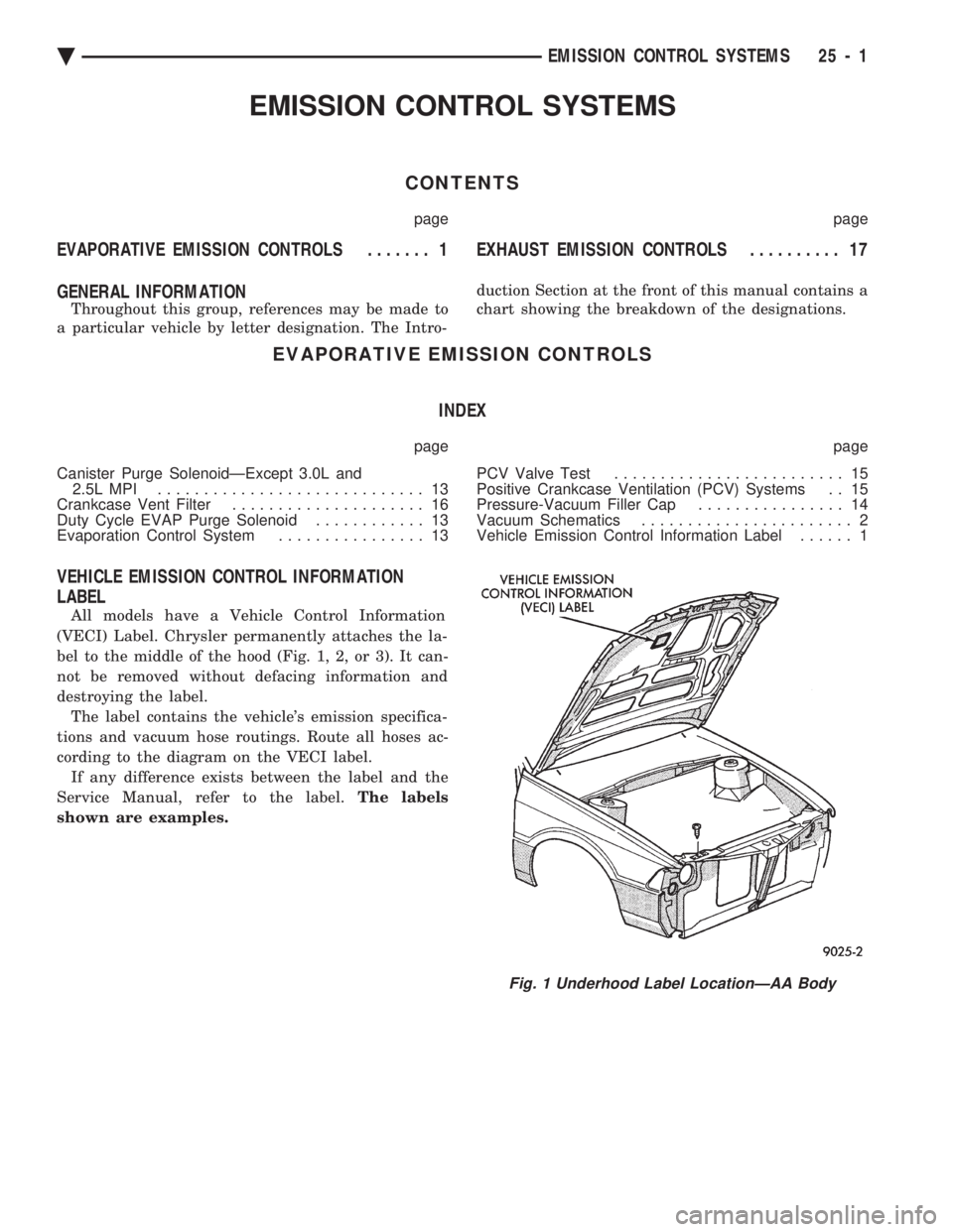
VEHICLE EMISSION CONTROL INFORMATION
LABEL
All models have a Vehicle Control Information
(VECI) Label. Chrysler permanently attaches the la-
bel to the middle of the hood (Fig. 1, 2, or 3). It can-
not be removed without defacing information and
destroying the label. The label contains the vehicle's emission specifica-
tions and vacuum hose routings. Route all hoses ac-
cording to the diagram on the VECI label. If any difference exists between the label and the
Service Manual, refer to the label. The labels
shown are examples.
Fig. 1 Underhood Label LocationÐAA Body
Ä EMISSION CONTROL SYSTEMS 25 - 1