1993 CHEVROLET DYNASTY service
[x] Cancel search: servicePage 2355 of 2438
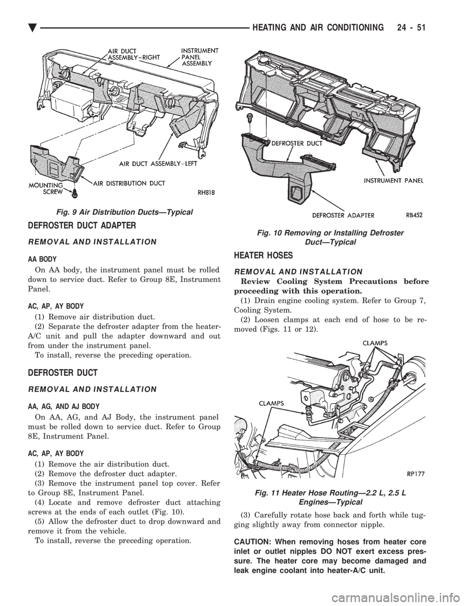
DEFROSTER DUCT ADAPTER
REMOVAL AND INSTALLATION
AA BODY On AA body, the instrument panel must be rolled
down to service duct. Refer to Group 8E, Instrument
Panel.
AC, AP, AY BODY
(1) Remove air distribution duct.
(2) Separate the defroster adapter from the heater-
A/C unit and pull the adapter downward and out
from under the instrument panel. To install, reverse the preceding operation.
DEFROSTER DUCT
REMOVAL AND INSTALLATION
AA, AG, AND AJ BODY
On AA, AG, and AJ Body, the instrument panel
must be rolled down to service duct. Refer to Group
8E, Instrument Panel.
AC, AP, AY BODY
(1) Remove the air distribution duct.
(2) Remove the defroster duct adapter.
(3) Remove the instrument panel top cover. Refer
to Group 8E, Instrument Panel. (4) Locate and remove defroster duct attaching
screws at the ends of each outlet (Fig. 10). (5) Allow the defroster duct to drop downward and
remove it from the vehicle. To install, reverse the preceding operation.
HEATER HOSES
REMOVAL AND INSTALLATION
Review Cooling System Precautions before
proceeding with this operation. (1) Drain engine cooling system. Refer to Group 7,
Cooling System. (2) Loosen clamps at each end of hose to be re-
moved (Figs. 11 or 12).
(3) Carefully rotate hose back and forth while tug-
ging slightly away from connector nipple.
CAUTION: When removing hoses from heater core
inlet or outlet nipples DO NOT exert excess pres-
sure. The heater core may become damaged and
leak engine coolant into heater-A/C unit.
Fig. 9 Air Distribution DuctsÐTypical
Fig. 10 Removing or Installing Defroster DuctÐTypical
Fig. 11 Heater Hose RoutingÐ2.2 L, 2.5 LEnginesÐTypical
Ä HEATING AND AIR CONDITIONING 24 - 51
Page 2357 of 2438
FIN-SENSING CYCLING CLUTCH SWITCH
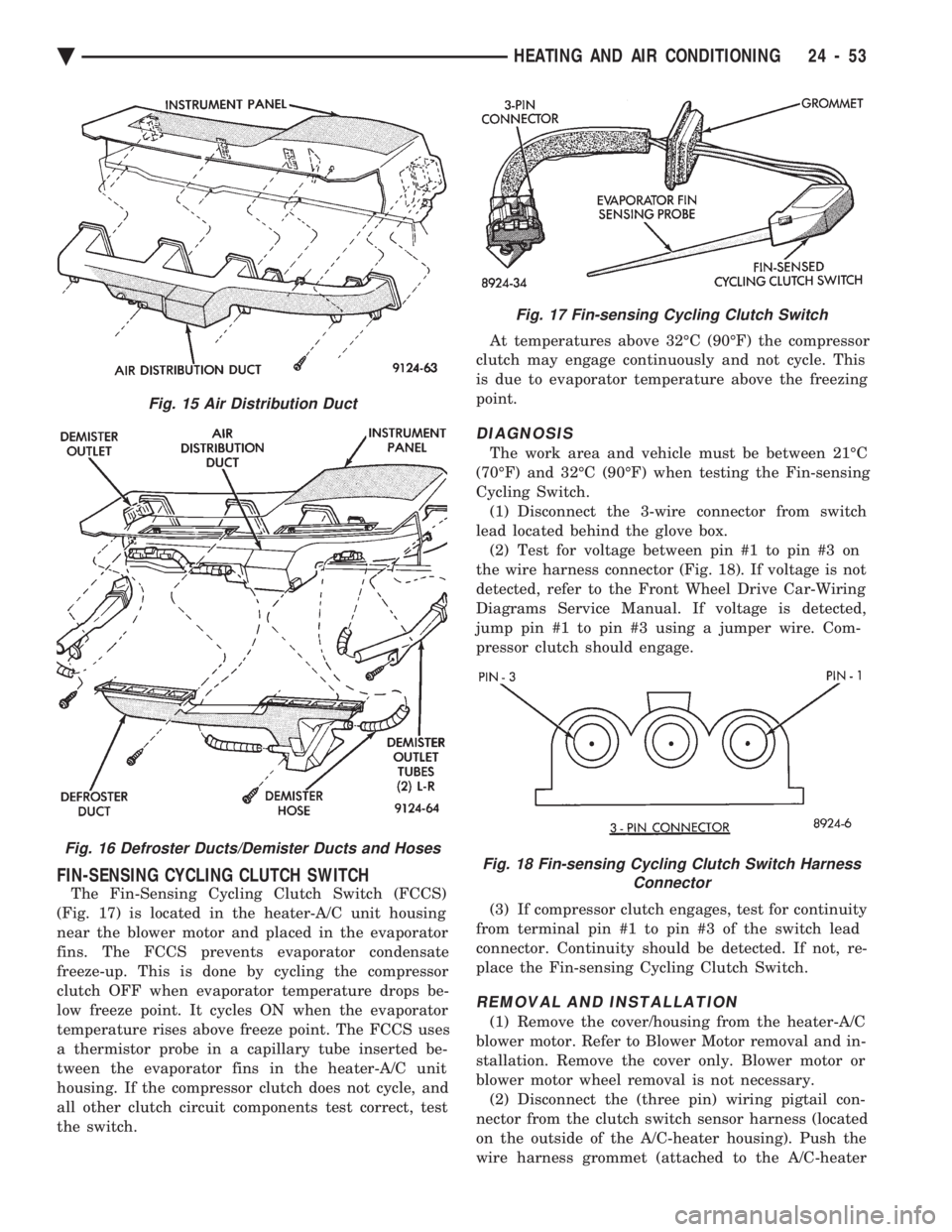
The Fin-Sensing Cycling Clutch Switch (FCCS)
(Fig. 17) is located in the heater-A/C unit housing
near the blower motor and placed in the evaporator
fins. The FCCS prevents evaporator condensate
freeze-up. This is done by cycling the compressor
clutch OFF when evaporator temperature drops be-
low freeze point. It cycles ON when the evaporator
temperature rises above freeze point. The FCCS uses
a thermistor probe in a capillary tube inserted be-
tween the evaporator fins in the heater-A/C unit
housing. If the compressor clutch does not cycle, and
all other clutch circuit components test correct, test
the switch. At temperatures above 32ÉC (90ÉF) the compressor
clutch may engage continuously and not cycle. This
is due to evaporator temperature above the freezing
point.
DIAGNOSIS
The work area and vehicle must be between 21ÉC
(70ÉF) and 32ÉC (90ÉF) when testing the Fin-sensing
Cycling Switch. (1) Disconnect the 3-wire connector from switch
lead located behind the glove box. (2) Test for voltage between pin #1 to pin #3 on
the wire harness connector (Fig. 18). If voltage is not
detected, refer to the Front Wheel Drive Car-Wiring
Diagrams Service Manual. If voltage is detected,
jump pin #1 to pin #3 using a jumper wire. Com-
pressor clutch should engage.
(3) If compressor clutch engages, test for continuity
from terminal pin #1 to pin #3 of the switch lead
connector. Continuity should be detected. If not, re-
place the Fin-sensing Cycling Clutch Switch.
REMOVAL AND INSTALLATION
(1) Remove the cover/housing from the heater-A/C
blower motor. Refer to Blower Motor removal and in-
stallation. Remove the cover only. Blower motor or
blower motor wheel removal is not necessary. (2) Disconnect the (three pin) wiring pigtail con-
nector from the clutch switch sensor harness (located
on the outside of the A/C-heater housing). Push the
wire harness grommet (attached to the A/C-heater
Fig. 15 Air Distribution Duct
Fig. 16 Defroster Ducts/Demister Ducts and Hoses
Fig. 17 Fin-sensing Cycling Clutch Switch
Fig. 18 Fin-sensing Cycling Clutch Switch Harness Connector
Ä HEATING AND AIR CONDITIONING 24 - 53
Page 2358 of 2438
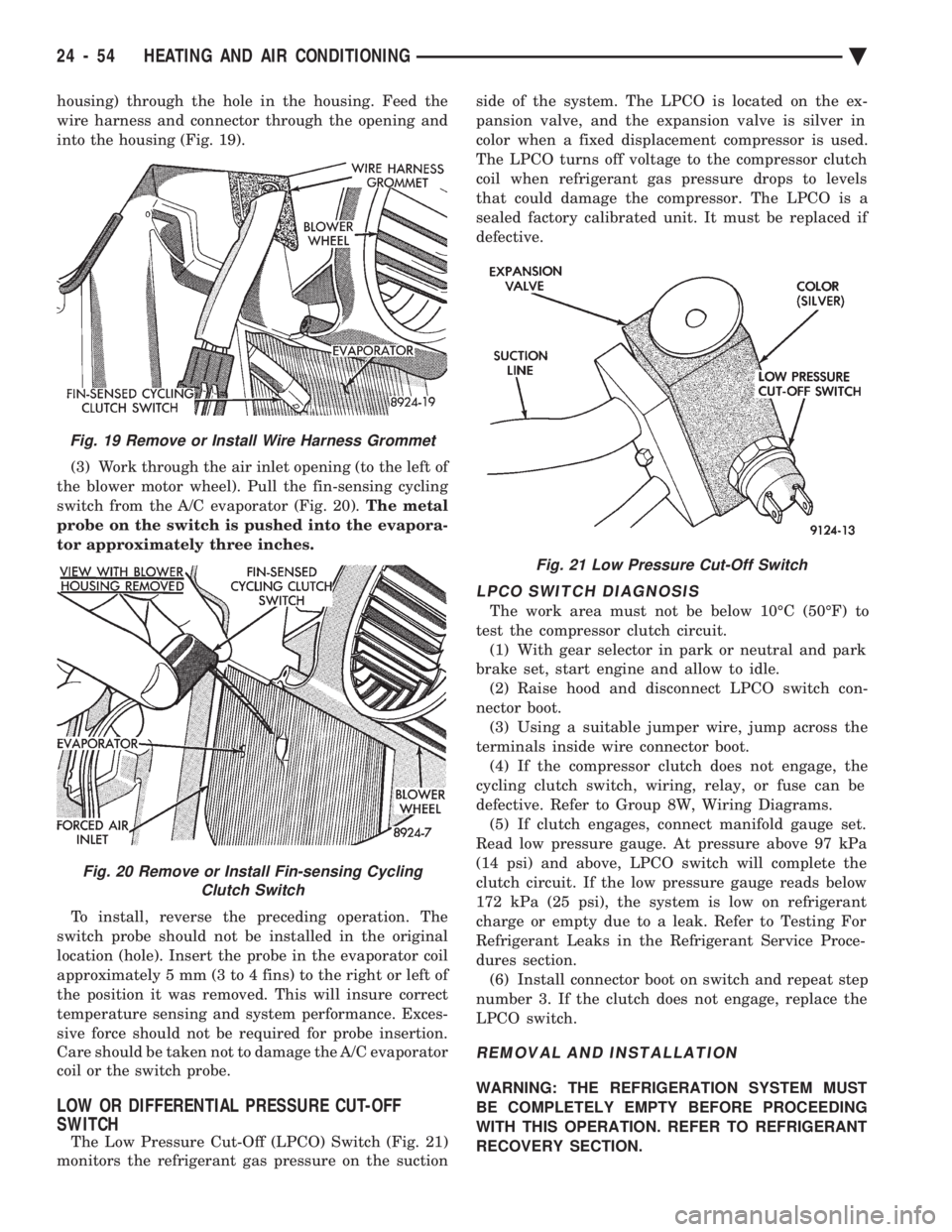
housing) through the hole in the housing. Feed the
wire harness and connector through the opening and
into the housing (Fig. 19). (3) Work through the air inlet opening (to the left of
the blower motor wheel). Pull the fin-sensing cycling
switch from the A/C evaporator (Fig. 20). The metal
probe on the switch is pushed into the evapora-
tor approximately three inches.
To install, reverse the preceding operation. The
switch probe should not be installed in the original
location (hole). Insert the probe in the evaporator coil
approximately 5 mm (3 to 4 fins) to the right or left of
the position it was removed. This will insure correct
temperature sensing and system performance. Exces-
sive force should not be required for probe insertion.
Care should be taken not to damage the A/C evaporator
coil or the switch probe.
LOW OR DIFFERENTIAL PRESSURE CUT-OFF
SWITCH
The Low Pressure Cut-Off (LPCO) Switch (Fig. 21)
monitors the refrigerant gas pressure on the suction side of the system. The LPCO is located on the ex-
pansion valve, and the expansion valve is silver in
color when a fixed displacement compressor is used.
The LPCO turns off voltage to the compressor clutch
coil when refrigerant gas pressure drops to levels
that could damage the compressor. The LPCO is a
sealed factory calibrated unit. It must be replaced if
defective.
LPCO SWITCH DIAGNOSIS
The work area must not be below 10ÉC (50ÉF) to
test the compressor clutch circuit. (1) With gear selector in park or neutral and park
brake set, start engine and allow to idle. (2) Raise hood and disconnect LPCO switch con-
nector boot. (3) Using a suitable jumper wire, jump across the
terminals inside wire connector boot. (4) If the compressor clutch does not engage, the
cycling clutch switch, wiring, relay, or fuse can be
defective. Refer to Group 8W, Wiring Diagrams. (5) If clutch engages, connect manifold gauge set.
Read low pressure gauge. At pressure above 97 kPa
(14 psi) and above, LPCO switch will complete the
clutch circuit. If the low pressure gauge reads below
172 kPa (25 psi), the system is low on refrigerant
charge or empty due to a leak. Refer to Testing For
Refrigerant Leaks in the Refrigerant Service Proce-
dures section. (6) Install connector boot on switch and repeat step
number 3. If the clutch does not engage, replace the
LPCO switch.
REMOVAL AND INSTALLATION
WARNING: THE REFRIGERATION SYSTEM MUST
BE COMPLETELY EMPTY BEFORE PROCEEDING
WITH THIS OPERATION. REFER TO REFRIGERANT
RECOVERY SECTION.
Fig. 21 Low Pressure Cut-Off Switch
Fig. 19 Remove or Install Wire Harness Grommet
Fig. 20 Remove or Install Fin-sensing Cycling Clutch Switch
24 - 54 HEATING AND AIR CONDITIONING Ä
Page 2359 of 2438
(1) Disconnect the boot like wire connector at the
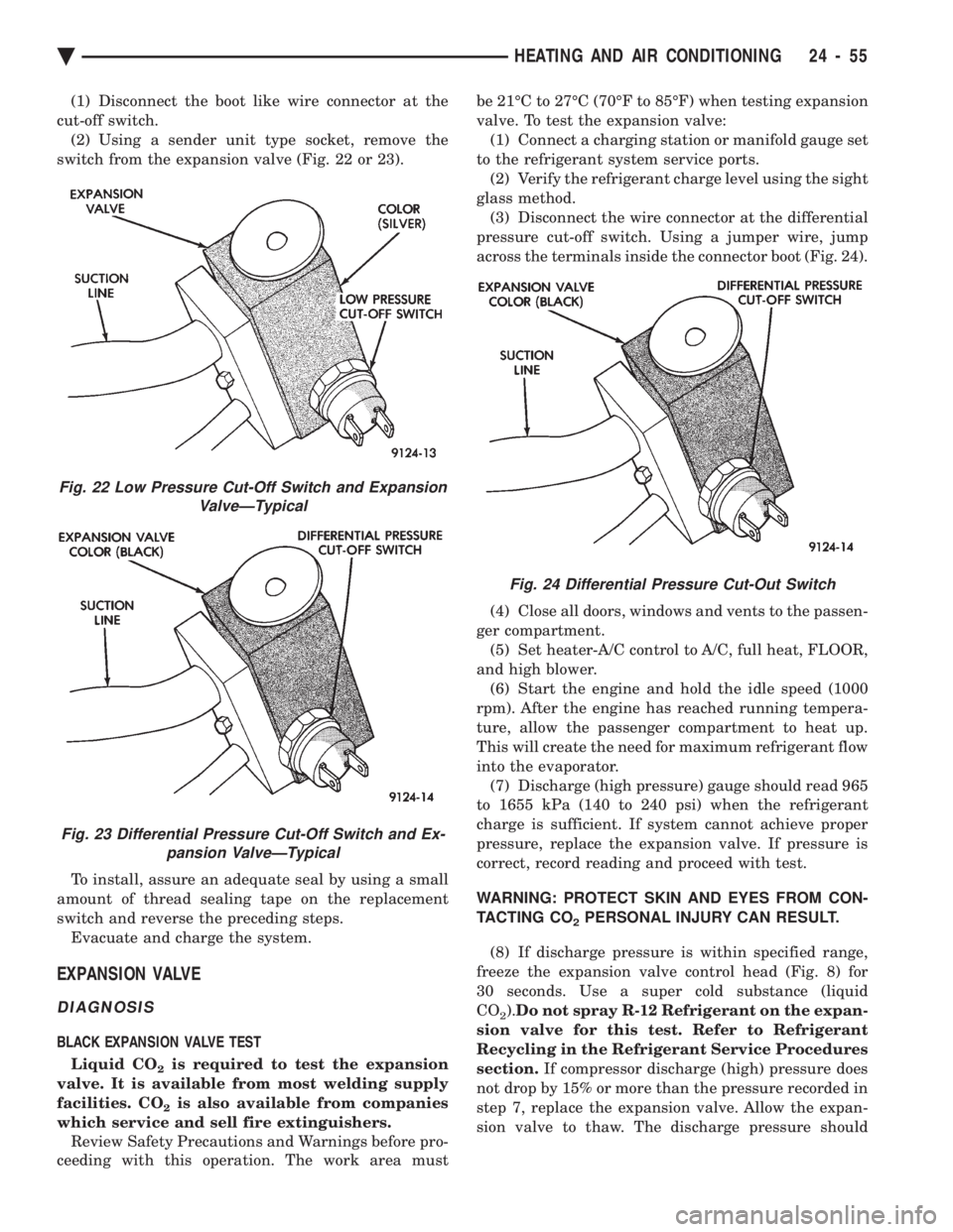
cut-off switch. (2) Using a sender unit type socket, remove the
switch from the expansion valve (Fig. 22 or 23).
To install, assure an adequate seal by using a small
amount of thread sealing tape on the replacement
switch and reverse the preceding steps. Evacuate and charge the system.
EXPANSION VALVE
DIAGNOSIS
BLACK EXPANSION VALVE TEST
Liquid CO
2is required to test the expansion
valve. It is available from most welding supply
facilities. CO
2is also available from companies
which service and sell fire extinguishers. Review Safety Precautions and Warnings before pro-
ceeding with this operation. The work area must be 21ÉC to 27ÉC (70ÉF to 85ÉF) when testing expansion
valve. To test the expansion valve: (1) Connect a charging station or manifold gauge set
to the refrigerant system service ports. (2) Verify the refrigerant charge level using the sight
glass method. (3) Disconnect the wire connector at the differential
pressure cut-off switch. Using a jumper wire, jump
across the terminals inside the connector boot (Fig. 24).
(4) Close all doors, windows and vents to the passen-
ger compartment. (5) Set heater-A/C control to A/C, full heat, FLOOR,
and high blower. (6) Start the engine and hold the idle speed (1000
rpm). After the engine has reached running tempera-
ture, allow the passenger compartment to heat up.
This will create the need for maximum refrigerant flow
into the evaporator. (7) Discharge (high pressure) gauge should read 965
to 1655 kPa (140 to 240 psi) when the refrigerant
charge is sufficient. If system cannot achieve proper
pressure, replace the expansion valve. If pressure is
correct, record reading and proceed with test.
WARNING: PROTECT SKIN AND EYES FROM CON-
TACTING CO
2PERSONAL INJURY CAN RESULT.
(8) If discharge pressure is within specified range,
freeze the expansion valve control head (Fig. 8) for
30 seconds. Use a super cold substance (liquid
CO
2). Do not spray R-12 Refrigerant on the expan-
sion valve for this test. Refer to Refrigerant
Recycling in the Refrigerant Service Procedures
section. If compressor discharge (high) pressure does
not drop by 15% or more than the pressure recorded in
step 7, replace the expansion valve. Allow the expan-
sion valve to thaw. The discharge pressure should
Fig. 22 Low Pressure Cut-Off Switch and Expansion ValveÐTypical
Fig. 23 Differential Pressure Cut-Off Switch and Ex-pansion ValveÐTypical
Fig. 24 Differential Pressure Cut-Out Switch
Ä HEATING AND AIR CONDITIONING 24 - 55
Page 2360 of 2438
stabilize to the pressure recorded in step 7. If the
pressure does not stabilize, replace the expansion
valve.When expansion valve tests are complete, refer to
Heater and A/C Performance Tests and remove all test
equipment before returning vehicle to use.
SILVER EXPANSION VALVE TEST
Expansion valve tests should be performed af-
ter compressor tests. Liquid CO
2is required to test the expansion
valve. It is available from most welding supply
facilities. CO
2is also available from companies
which service and sell fire extinguishers. Review Safety Precautions and Warnings in the
General Information section of this Group. The work
area and vehicle must be 21ÉC to 27ÉC (70ÉF to 85ÉF)
when testing expansion valve. To test the expansion
valve: (1) Connect a charging station or manifold gauge set
to the refrigerant system service ports. (2) Verify the refrigerant charge level using the sight
glass method. (3) Disconnect wire connector at low pressure cut-off
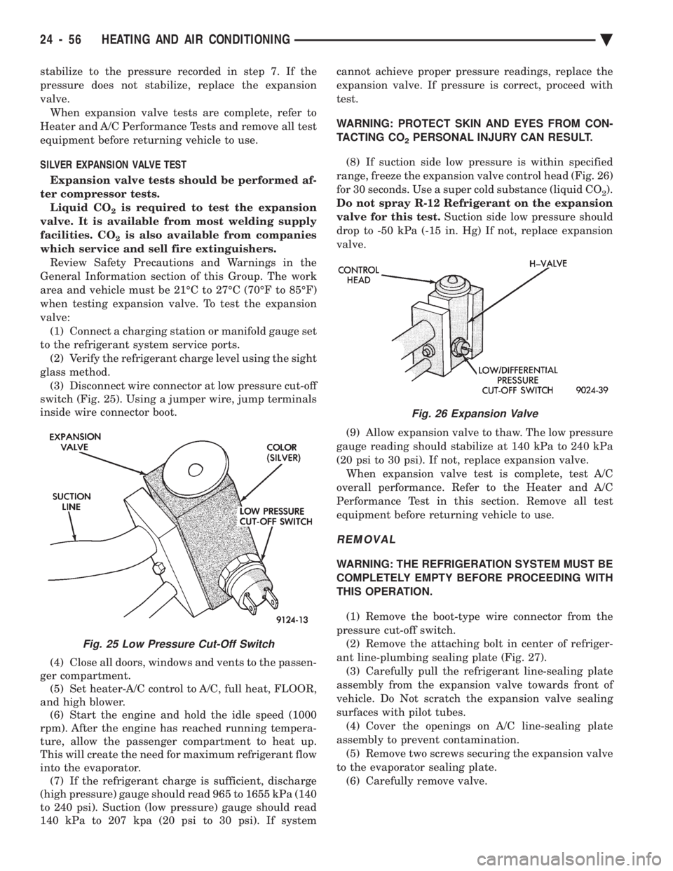
switch (Fig. 25). Using a jumper wire, jump terminals
inside wire connector boot.
(4) Close all doors, windows and vents to the passen-
ger compartment. (5) Set heater-A/C control to A/C, full heat, FLOOR,
and high blower. (6) Start the engine and hold the idle speed (1000
rpm). After the engine has reached running tempera-
ture, allow the passenger compartment to heat up.
This will create the need for maximum refrigerant flow
into the evaporator. (7) If the refrigerant charge is sufficient, discharge
(high pressure) gauge should read 965 to 1655 kPa (140
to 240 psi). Suction (low pressure) gauge should read
140 kPa to 207 kpa (20 psi to 30 psi). If system cannot achieve proper pressure readings, replace the
expansion valve. If pressure is correct, proceed with
test.
WARNING: PROTECT SKIN AND EYES FROM CON-
TACTING CO
2PERSONAL INJURY CAN RESULT.
(8) If suction side low pressure is within specified
range, freeze the expansion valve control head (Fig. 26)
for 30 seconds. Use a super cold substance (liquid CO
2).
Do not spray R-12 Refrigerant on the expansion
valve for this test. Suction side low pressure should
drop to -50 kPa (-15 in. Hg) If not, replace expansion
valve.
(9) Allow expansion valve to thaw. The low pressure
gauge reading should stabilize at 140 kPa to 240 kPa
(20 psi to 30 psi). If not, replace expansion valve. When expansion valve test is complete, test A/C
overall performance. Refer to the Heater and A/C
Performance Test in this section. Remove all test
equipment before returning vehicle to use.
REMOVAL
WARNING: THE REFRIGERATION SYSTEM MUST BE
COMPLETELY EMPTY BEFORE PROCEEDING WITH
THIS OPERATION.
(1) Remove the boot-type wire connector from the
pressure cut-off switch. (2) Remove the attaching bolt in center of refriger-
ant line-plumbing sealing plate (Fig. 27). (3) Carefully pull the refrigerant line-sealing plate
assembly from the expansion valve towards front of
vehicle. Do Not scratch the expansion valve sealing
surfaces with pilot tubes. (4) Cover the openings on A/C line-sealing plate
assembly to prevent contamination. (5) Remove two screws securing the expansion valve
to the evaporator sealing plate. (6) Carefully remove valve.
Fig. 25 Low Pressure Cut-Off Switch
Fig. 26 Expansion Valve
24 - 56 HEATING AND AIR CONDITIONING Ä
Page 2370 of 2438
AUTOMATIC TEMPERATURE CONTROL (ATC) INDEX
page page
Ambient Temperature Sensor ............... 67
ATC Computer/Control Panel ................ 66
Blend-Air Door Actuator .................... 69
Computer Aided Diagnostic Tests ............ 72
Diagnostic Trouble Code Definitions .......... 73
Diagnostic Trouble Code Service Procedures . . . 74
Erasing Diagnostic Trouble Codes ............ 83
Fresh/Recirc Door Actuator ................. 68 General InformationÐComponent Operation
.... 66
In-Car Temperature Sensor/Aspirator Assembly . . 70
Manual A/C Mode ........................ 66
Mode Door Actuator ...................... 69
NonÐComputer Aided Diagnostic Tests ....... 72
Power Module ........................... 67
Sun Sensor ............................. 71
Water Temperature Sensor ................. 71
GENERAL INFORMATIONÐCOMPONENT
OPERATION
The Automatic Temperature Control (ATC) system
lets the operator change the passenger compartment
environment. A computer, built into the control
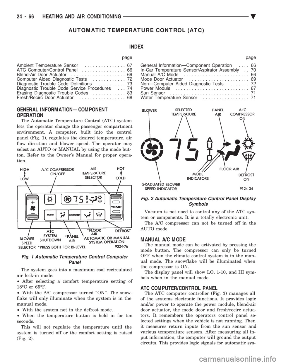
panel (Fig. 1), regulates the desired temperature, air
flow direction and blower speed. The operator may
select an AUTO or MANUAL by using the mode but-
ton. Refer to the Owner's Manual for proper opera-
tion.
The system goes into a maximum cool recirculated
air lock-in mode:
² After selecting a comfort temperature setting of
18ÉC or 65ÉF.
² With the A/C compressor turned ``ON''. The snow-
flake will only illuminate when the system is in the
manual mode.
² With the system not in the defrost mode.
² When the temperature button is held in for ten
seconds. This will not regulate the temperature until the
system is turned off or the comfort setting is raised
(Fig. 2). Vacuum is not used to control any of the ATC sys-
tem or components. It is a totally electronic unit. The A/C compressor can not be turned off in the
AUTO mode.
MANUAL A/C MODE
The manual mode can be activated by pressing the
mode button. The compressor can only be turned
OFF when the climate control system is in the man-
ual mode. The snowflake will be illuminated when
the compressor is ON. The display panel will show LO, 1-10, and HI sym-
bols when in the manual mode.
ATC COMPUTER/CONTROL PANEL
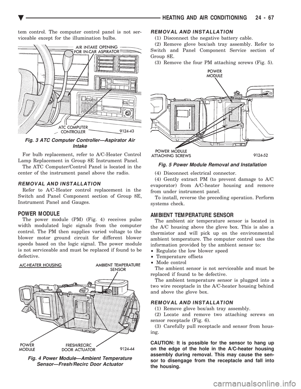
The ATC computer controller (Fig. 3) manages all
of the systems electronic functions. It provides logic
and/or power to operate the power module, blend-air
door actuator, the mode door and fresh/recirc actua-
tors. It remembers the operators control panel se-
lected settings when the vehicle is not running. Then
it measures return inputs from the sun sensor and
various temperature sensors. After measuring all in-
put information, the computer will ground the output
circuits. This provides logic signals for automatic sys-
Fig. 1 Automatic Temperature Control Computer Panel
Fig. 2 Automatic Temperature Control Panel Display Symbols
24 - 66 HEATING AND AIR CONDITIONING Ä
Page 2371 of 2438
tem control. The computer control panel is not ser-
viceable except for the illumination bulbs. For bulb replacement, refer to A/C-Heater Control
Lamp Replacement in Group 8E Instrument Panel. The ATC Computer/Control Panel is located in the
center of the instrument panel above the radio.
REMOVAL AND INSTALLATION
Refer to A/C-Heater control replacement in the
Switch and Panel Component section of Group 8E,
Instrument Panel and Gauges.
POWER MODULE
The power module (PM) (Fig. 4) receives pulse
width modulated logic signals from the computer
control. The PM then supplies varied voltage to the
blower motor ground circuit for different blower
speeds based on the logic signal. The power module
is not serviceable and must be replaced if found to be
defective.
REMOVAL AND INSTALLATION
(1) Disconnect the negative battery cable.
(2) Remove glove box/ash tray assembly. Refer to
Switch and Panel Component Service section of
Group 8E. (3) Remove the four PM attaching screws (Fig. 5).
(4) Disconnect electrical connector.
(4) Gently extract PM (to prevent damage to A/C
evaporator) from A/C-heater housing and remove
from under instrument panel. To install, reverse the preceding operation. Perform
systems check.
AMBIENT TEMPERATURE SENSOR
The ambient air temperature sensor is located in
the A/C housing above the glove box. This is also a
thermistor and will pick up on the environmental
ambient temperature. The computer control uses the
information provided by the ambient sensor to:
² Regulate the low blower speed
² Temperature offsets
² Mode control
The ambient sensor is not serviceable and must be
replaced if found to be defective. The ambient temperature sensor is plugged into a
two wire receptacle in the A/C-heater housing behind
and above the glove box.
REMOVAL AND INSTALLATION
(1) Remove glove box/ash tray assembly.
(2) Locate and remove two attaching screws on
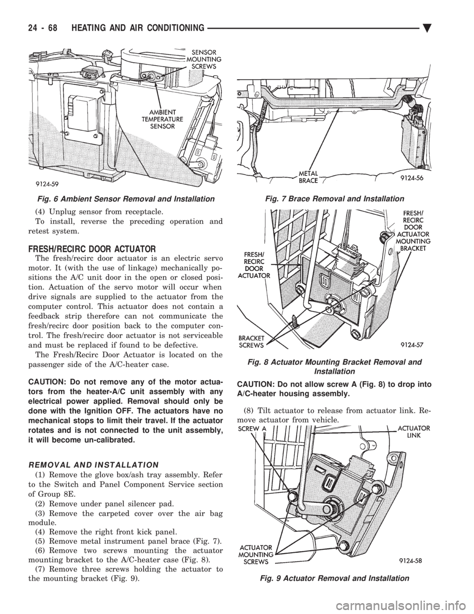
sensor receptacle (Fig. 6). (3) Carefully pull receptacle and sensor from hous-
ing.
CAUTION: It is possible for the sensor to hang up
on the edge of the hole in the A/C-heater housing
assembly during removal. This may cause the sen-
sor to disengage from the receptacle and fall into
the housing.
Fig. 3 ATC Computer ControllerÐAspirator Air Intake
Fig. 4 Power ModuleÐAmbient TemperatureSensorÐFresh/Recirc Door Actuator
Fig. 5 Power Module Removal and Installation
Ä HEATING AND AIR CONDITIONING 24 - 67
Page 2372 of 2438
(4) Unplug sensor from receptacle.
To install, reverse the preceding operation and
retest system.
FRESH/RECIRC DOOR ACTUATOR
The fresh/recirc door actuator is an electric servo
motor. It (with the use of linkage) mechanically po-
sitions the A/C unit door in the open or closed posi-
tion. Actuation of the servo motor will occur when
drive signals are supplied to the actuator from the
computer control. This actuator does not contain a
feedback strip therefore can not communicate the
fresh/recirc door position back to the computer con-
trol. The fresh/recirc door actuator is not serviceable
and must be replaced if found to be defective. The Fresh/Recirc Door Actuator is located on the
passenger side of the A/C-heater case.
CAUTION: Do not remove any of the motor actua-
tors from the heater-A/C unit assembly with any
electrical power applied. Removal should only be
done with the Ignition OFF. The actuators have no
mechanical stops to limit their travel. If the actuator
rotates and is not connected to the unit assembly,
it will become un-calibrated.
REMOVAL AND INSTALLATION
(1) Remove the glove box/ash tray assembly. Refer
to the Switch and Panel Component Service section
of Group 8E. (2) Remove under panel silencer pad.
(3) Remove the carpeted cover over the air bag
module. (4) Remove the right front kick panel.
(5) Remove metal instrument panel brace (Fig. 7).
(6) Remove two screws mounting the actuator
mounting bracket to the A/C-heater case (Fig. 8). (7) Remove three screws holding the actuator to
the mounting bracket (Fig. 9). CAUTION: Do not allow screw A (Fig. 8) to drop into
A/C-heater housing assembly.
(8) Tilt actuator to release from actuator link. Re-
move actuator from vehicle.
Fig. 9 Actuator Removal and Installation
Fig. 6 Ambient Sensor Removal and InstallationFig. 7 Brace Removal and Installation
Fig. 8 Actuator Mounting Bracket Removal and Installation
24 - 68 HEATING AND AIR CONDITIONING Ä