1993 CHEVROLET DYNASTY turn signal
[x] Cancel search: turn signalPage 479 of 2438

FAILURE TO START TEST
This no-start test checks the camshaft position sen-
sor and crankshaft position sensor. The powertrain control module (PCM) supplies 8.0
volts to the camshaft position sensor and crankshaft
position sensor through one circuit. If the 8.0-volt
supply circuit shorts to ground, neither sensor will
produce a signal (output voltage to the PCM). When the ignition key is turned and left in the On
position , the PCM automatically energizes the auto shutdown (ASD) relay. However, the PCM de-energizes
the relay within one second because it has not received
a crankshaft position sensor signal indicating engine
rotation.
During cranking, the ASD relay will not energize
until the PCM receives a crankshaft signal. Secondly,
the ASD relay remains energized only if the PCM
senses a camshaft position sensor signal immediately
after detecting the crankshaft position sensor signal. (1) Check battery voltage. Voltage should approxi-
mately 12.66 volts or higher to perform failure to start
test. (2) Disconnect the harness connector from the coil
pack (Fig. 2). (3) Connect a test light to the B+ (battery voltage)
terminal of the coil electrical connector and ground.
The wire for the B+ terminal is dark green with a black
tracer. (4) Turn the ignition key to the ON position.The
test light should flash On and then Off. Do not turn
the Key to off position, leave it in the On position .
(a) If the test light flashes momentarily, the PCM
grounded the auto shutdown (ASD) relay. Proceed to
step 5. (b) If the test light did not flash, the ASD relay did
not energize. The cause is either the relay or one of
the relay circuits. Use the DRBII scan tool to test the
ASD relay and circuits. Refer to the appropriate
Powertrain Diagnostics Procedure Manual. Refer to
the wiring diagrams section for circuit information.
(5) Crank the engine. If the key was placed in the off
position after step 4, place the key in the On position
before cranking. Wait for the test light to flash once,
then crank the engine. (a) If the test light momentarily flashes during
cranking, the PCM is not receiving a camshaft posi-
tion sensor signal. Use the DRBII scan tool to test the
camshaft position sensor and sensor circuits. Refer to
the appropriate Powertrain Diagnostics Procedure
Manual. Refer to the wiring diagrams section for
circuit information. (b) If the test light did not flash during cranking,
unplug the camshaft position sensor connector. Turn
the ignition key to the off position. Turn the key to
the On position, wait for the test light to momen-
tarily flash once, then crank the engine. If the test
light momentarily flashes, the camshaft position
sensor is shorted and must be replaced. If the light
did not flash, the cause of the no-start is in either the
crankshaft position sensor/camshaft position sensor
8.0-volt supply circuit, or the crankshaft position
sensor 5-volt output or ground circuits. Use the
DRBII scan tool to test the crankshaft position sen-
sor and the sensor circuits.
Fig. 6 Ignition Coil Electrical Connection
Fig. 7 Ignition Coil Terminal Identification
Fig. 8 Checking Ignition Coil Secondary Resistance
Ä IGNITION SYSTEMS 8D - 37
Page 522 of 2438

(b) Refer to sending unit removal Group 14, Fuel.
(c) Connect sending unit wire and jumper wire
as described in the test procedure.
(5) If fuel gauge now checks within specifications,
original sending unit is electrically okay, check fol-
lowing as a possible cause: (a) Ground wire from sending unit to left side
cowl for continuity. (b) Sending unit deformed. Make sure sending
unit float arm moves freely and pick up tube is not
bent upwards creating an interference with bottom
of tank and inspect float. (c) Sending unit improperly installed. Install
properly. (d) Mounting flange on fuel tank for sending
unit deformed. Feel for interference fit of sending
unit to bottom of tank. It is permissible to bend
pick up tube down a little near mounting flange to
gain interference fit. (e) Fuel tank bottom deformed, causing improper
positioning of sending unit pick up tube. Replace or
repair tank and recheck sending unit.
GAUGE CALIBRATION
(1) Remove the gauge.
(2) Check for ignition voltage and ground to the
gauge. (3) With the ignition key in the OFF position, re-
place gauge. Turn the ignition key to the ON posi-
tion. To test oil pressure gauge engine must be
running. When testing oil or temperature gauge the
engine should be at normal operating temperature.
Record the gauge position. (4) Remove gauge and record the resistance be-
tween the sending unit pin and the gauge ground
pin. When checking gauges, it is important to have
the same engine temperature and speed when noting
gauge position. The time between gauge reading and
measuring should be kept to a minimum. (5) The resistance Chart (Fig. 21), is general
guidelines for checking the gauge position against
the sending unit resistance. Because of only a few specific points of gauge posi-
tion versus sending unit resistance, a good estimate
is need when the resistance falls between gradua-
tions. Even when the resistance corresponds to grad-
uations, the gauge has a tolerance of 64 ohms.
Volt gauge: The calibration dot on the volt gauge
corresponds to 13 volts between the gauge ignition
and ground pins. If voltage varies from this, estimate
proper gauge position with input voltage.
VOLTMETER REPLACEMENT
(1) Remove cluster bezels and mask (Fig. 22).
(2) Remove screws attaching gauge assembly to
cluster. (3) Pull rearward to disengage gauge from gauge
pins. (4) For installation reverse above procedures.
OIL PRESSURE GAUGE REPLACEMENT
(1) Remove cluster bezels and mask/lens (Fig. 22).
(2) Remove screws attaching gauge assembly to
cluster.
(3) Pull rearward to disengaged gauge from gauge
pins.
(4) For installation reverse above procedures.
FUEL AND TEMPERATURE GAUGE ASSEMBLY REPLACEMENT
(1) Remove cluster bezel and mask/lens (Fig. 22).
(2) Remove oil pressure gauge.
(3) Remove screws attaching gauge assembly to
cluster.
(4) Pull rearward to disengage gauge from gauge
pins.
(5) For installation reverse above procedures.
SPEEDOMETER SYSTEM
AC body vehicles are equipped with electronically
driven speedometer and odometer assemblies. The unit
has the same appearance as a conventional speedometer
but it eliminates the cable-driven mechanical system. A
signal is sent from a transmission-mounted vehicle
speed sensor to the speedometer circuitry through the
wiring harness. By eliminating the speedometer cable,
instrument cluster service and removal is improved. Re-
fer to Fig. 23 Speedometer Diagnosis Chart. When the speedometer is out of calibration. The elec-
tronic automatic transaxle vehicle speed sensor output
must be calibrated to reflect the different combinations
of equipment. The procedure is called Pinion Factor, re-
fer to Group 21, Transaxle for the procedure.
Fig. 21 Gauge Resistance
8E - 30 INSTRUMENT PANEL AND GAUGES Ä
Page 543 of 2438

Perform cluster Self Diagnostic Test to determine
whether problem is within cluster or outside of clus-
ter. Refer to Fig. 24 and 25.
Successful completion of the SELF DIAGNOSTIC
TEST indicates that the problem is in the wiring,
connectors or sensors out side of the cluster.
CLUSTER ASSEMBLY REMOVAL
The electronic cluster which is serviced as an as-
sembly is removed with the same procedure as the
conventional cluster.
CONDITION: CLUSTER DISPLAYS DO NOT ILLUMINATE AFTER VEHICLE IS STARTED
(1) Check fuses and verify battery and ignition
voltage at cluster connector. (2) Check ground from cluster connector to instru-
ment panel ground stud.
SWITCH AND PANEL COMPONENT SERVICE
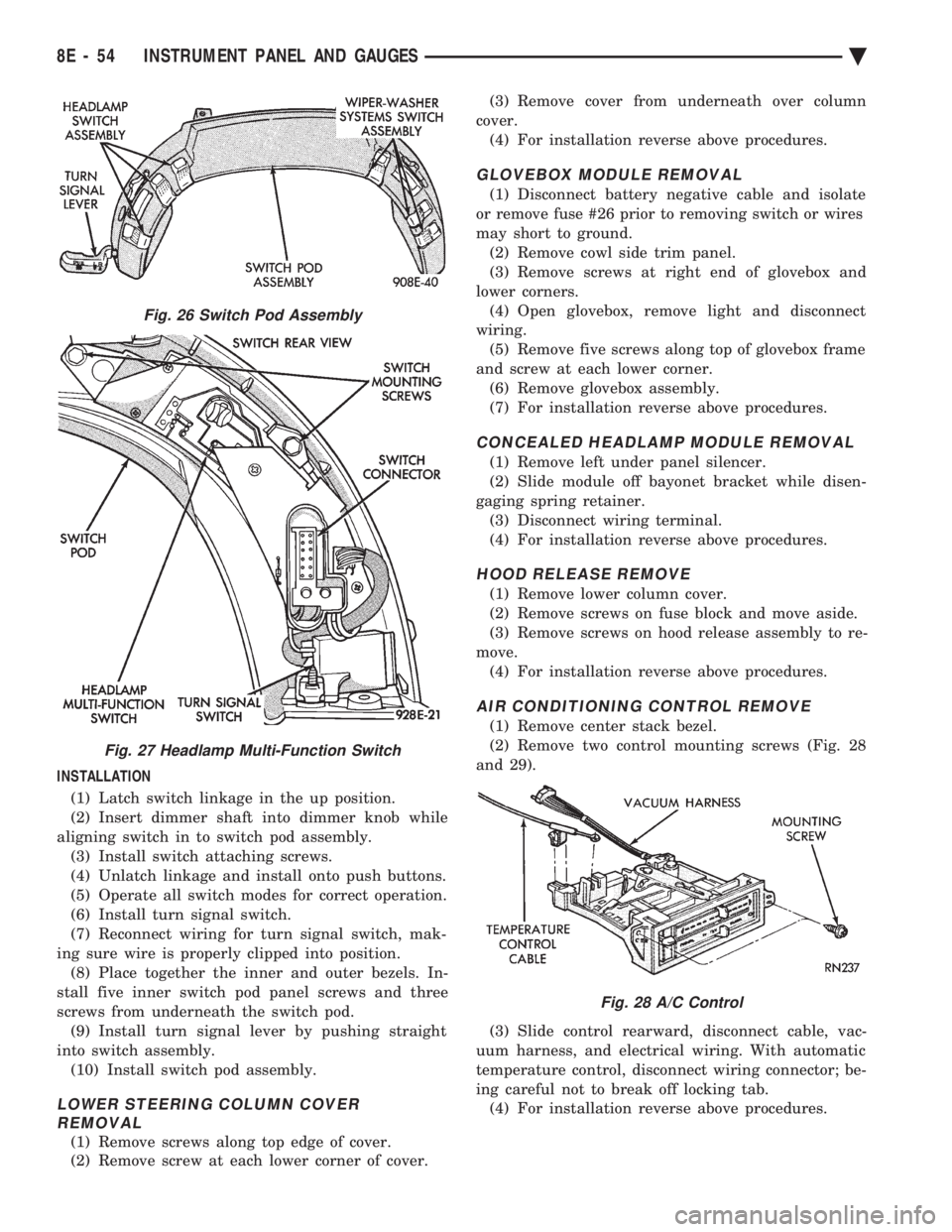
HEADLAMP SWITCH
The headlamp switch is located on the left side of
the switch pod. The switch controls the headlamps,
parking lamps, fog lamps and instrument light dim- ming. If any of the switches require replacement the
entire headlamp switch assembly must be replaced
(Fig. 26 and 27).
REMOVAL
(1) Remove switch pod assembly from the instru-
ment panel. DO NOT attempt to remove instrument
cluster dimmer switch or wiper delay switch knob,
they are not removable. (2) Remove turn signal switch lever by pulling
straight out of switch pod. (3) Remove screws from bottom of switch pod.
(4) Separate inner and outer switch pod halves and
remove turn signal switch to gain access to screw. (5) Remove five inner switch pod panel screws and
3 screws from underneath the switch pod. Separate
the inner bezel from the outer bezel. (6) Remove switch mounting screws before discon-
necting linkage. (7) Disconnect switch linkage from buttons. Pull
the linkage straight up from the switch/button to dis-
engage it and remove switch.
Fig. 23 Mechanical Cluster Lamp Location
Ä INSTRUMENT PANEL AND GAUGES 8E - 51
Page 546 of 2438

INSTALLATION (1) Latch switch linkage in the up position.
(2) Insert dimmer shaft into dimmer knob while
aligning switch in to switch pod assembly. (3) Install switch attaching screws.
(4) Unlatch linkage and install onto push buttons.
(5) Operate all switch modes for correct operation.
(6) Install turn signal switch.
(7) Reconnect wiring for turn signal switch, mak-
ing sure wire is properly clipped into position. (8) Place together the inner and outer bezels. In-
stall five inner switch pod panel screws and three
screws from underneath the switch pod. (9) Install turn signal lever by pushing straight
into switch assembly. (10) Install switch pod assembly.
LOWER STEERING COLUMN COVER REMOVAL
(1) Remove screws along top edge of cover.
(2) Remove screw at each lower corner of cover. (3) Remove cover from underneath over column
cover. (4) For installation reverse above procedures.
GLOVEBOX MODULE REMOVAL
(1) Disconnect battery negative cable and isolate
or remove fuse #26 prior to removing switch or wires
may short to ground. (2) Remove cowl side trim panel.
(3) Remove screws at right end of glovebox and
lower corners. (4) Open glovebox, remove light and disconnect
wiring. (5) Remove five screws along top of glovebox frame
and screw at each lower corner. (6) Remove glovebox assembly.
(7) For installation reverse above procedures.
CONCEALED HEADLAMP MODULE REMOVAL
(1) Remove left under panel silencer.
(2) Slide module off bayonet bracket while disen-
gaging spring retainer. (3) Disconnect wiring terminal.
(4) For installation reverse above procedures.
HOOD RELEASE REMOVE
(1) Remove lower column cover.
(2) Remove screws on fuse block and move aside.
(3) Remove screws on hood release assembly to re-
move. (4) For installation reverse above procedures.
AIR CONDITIONING CONTROL REMOVE
(1) Remove center stack bezel.
(2) Remove two control mounting screws (Fig. 28
and 29).
(3) Slide control rearward, disconnect cable, vac-
uum harness, and electrical wiring. With automatic
temperature control, disconnect wiring connector; be-
ing careful not to break off locking tab. (4) For installation reverse above procedures.
Fig. 26 Switch Pod Assembly
Fig. 27 Headlamp Multi-Function Switch
Fig. 28 A/C Control
8E - 54 INSTRUMENT PANEL AND GAUGES Ä
Page 550 of 2438

AP BODY INDEX
page page
Cluster and Gauge Service and Testing ....... 58
Gauges ................................ 61
General Information ....................... 58 Instrument Panel Replacement
.............. 72
Interior Lamp Replacement ................. 73
Switch and Panel Component Service ......... 67
GENERAL INFORMATION
INSTRUMENT CLUSTER
There are two conventional instrument cluster as-
semblies available. The clusters incorporates mag-
netic type gauges and an electronically driven
speedometer and odometer assembly (Fig. 1 and 2).
MAGNETIC GAUGES
All gauges on the AP Body clusters are the mag-
netic type gauges. When the ignition switch is in the
OFF position each gauge, except for the voltmeter
and tachometer will show a reading. However, the
readings are only accurate when the ignition switch
is in the ON position.
TACHOMETER DRIVE MODULE
The tachometer drive module is an electronic mod-
ule used to drive the magnetic tachometer in the
high line cluster. This module is located on top of the instrument
cluster.
ELECTRONIC DIGITAL CLOCK
The electronic digital clock is in the radio. The
clock and radio each use the display panel built into
the radio. A digital readout indicates the time in
hours and minutes whenever the ignition switch is in
the ON or ACC position. When the ignition switch is in the OFF position, or
when the radio frequency is being displayed, time
keeping is accurately maintained. The procedure for setting the clock varies slightly
with each radio. The correct procedure is described
under the individual radio operating instructions re-
fer to the Sound Systems Manual supplied with the
vehicle.
WARNING LAMPS AND INDICATOR LIGHTS
The instrument cluster has warning and indicators
lamps for eight different systems:
² Low oil pressure
² Brake warning
² Seat belt warning
² Malfunction indicator (check engine) lamp
² Air Bag
² High beam indicator
² Right and left turn signals.
² Anti-lock (ABS)
CLUSTER AND GAUGE SERVICE AND TESTING
CAUTION: Disconnect the negative battery cable
before servicing the instrument panel. When power
is required for test purposes, reconnect battery ca-
ble for test only. Disconnect the negative battery
cable after test and before continuing service pro-
cedures.
SENDING UNIT TEST
Check for a defective sending unit or wiring, when
a problem occurs with a cluster gauge. Do this before
disassembling the cluster. (1) Sending units and wiring can be checked by
grounding the connector leads, at the sending unit,
in the vehicle. (2) With the ignition in the ON position, a
grounded input will cause the fuel or temperature
gauge to read at or above maximum.
Fig. 1 Instrument Cluster With Tachometer
Fig. 2 Instrument Cluster Without Tachometer
8E - 58 INSTRUMENT PANEL AND GAUGES Ä
Page 613 of 2438

TURN SIGNALS AND HAZARD WARNING FLASHER
CONTENTS
page page
AG AND AJ BODIES ..................... 1
CHIME FUNCTIONÐAC, AG, AJ AND AY .... 1
DUAL-FUNCTION SWITCHÐAG AND AJ BODIES.5
GENERAL INFORMATION .................. 1
HAZARD WARNING SYSTEM .............. 1
MULTI-FUNCTION SWITCHÐAA, AC, AP AND AY BODIES .............................. 2 REMOTE TURN SIGNAL SWITCH REMOVALÐAG
AND AJ BODIES ....................... 5
TESTING PROCEDURES ................... 2
TURN SIGNAL AND HAZARD WARNING FLASHER LOCATION ............................ 6
TURN SIGNAL RELAYSÐAG AND AJ BODIES . 6
GENERAL INFORMATION
WARNING: ON VEHICLES EQUIPPED WITH AIR-
BAG, SEE GROUP 8M, RESTRAINT SYSTEMS FOR
AIRBAG REMOVAL PROCEDURES.
TURN SIGNALSÐAC, AY, AA AND AP BODIES
The turn signals are part of the multi-function switch.
Which contains electrical circuitry for turn signal, cor-
nering lamps, hazard warning, headlamp beam select,
headlamp optical horn, windshield wiper, pulse wipe
and windshield washer switching. The integrated switch
assembly is mounted to the left hand side of the steer-
ing column. When the driver wishes to signal his inten-
tions to change direction of travel, he moves the lever
upward to cause the right signals to flash and down-
ward to cause the left signals to flash. After completion
of a turn the system is deactivated automatically. As
the steering wheel returns to the straight ahead posi-
tion, a canceling cam of two lobes molded to the clock-
spring mechanism comes in contact with the cancel
actuator on the turn signal multi-function switch as-
sembly. Either cam lobe, pushing on the cancel actua-
tor, returns the switch to the off position. If only momentary signaling such as indication of a
lane change is desired, the switch is actuated to a left
or right intermediate detent position. In this position
the signal lamps flash as described above, but the
switch returns to the OFF position as soon as the lever
is released.
When the system is activated, 1 of 2 indicator
lamps mounted in the instrument cluster flashes in
unison with the turn signal lamps, indicating to the
driver that the system is operating.
AG AND AJ BODIES
The turn signals are actuated with lever on the left
side of the instrument panel switch pod. When the
driver wishes to signal his intentions to change di- rection of travel, he moves the lever upward to cause
the right signals to flash and downward to cause the
left signals to flash. After completion of a turn the system is deacti-
vated automatically. The cancellation switch in the
steering column sends a signal to a remote turn sig-
nal switch in the switch pod to cancel the turn signal
function. As the steering wheel returns to the
straight ahead position from a turn, a cancel cam
which is located on the steering wheel contacts a
cancel flipper located on the cancellation switch.
When the flipper is contacted by the cancel cam in
the proper rotational direction, the cancel switch
sends a signal to the remote turn signal switch. If only momentary signaling such as indication of a
lane change is desired, the switch is actuated to a
left or right intermediate detent position. In this po-
sition the signal lamps flash as described above, but
the switch returns to the OFF position as soon as the
lever is released. When the system is activated, 1 of 2 indicator
lamps mounted in the instrument cluster flashes in
unison with the turn signal lamps, indicating to the
driver that the system is operating.
HAZARD WARNING SYSTEM
The hazard warning system is actuated by a push
button located on the top of the steering column be-
tween the steering wheel and the instrument panel.
The hazard switch is identified with a double trian-
gle on top of the button. Push and release the button
to turn the hazard function ON or OFF. The button
will move out from the steering column in the ON
position and will remain in toward the column in the
OFF position.
CHIME FUNCTIONÐAC, AG, AJ AND AY
The chime will sound after the vehicle has traveled
a distance of 0.6 miles at a speed above 15 miles per
hour.
Ä TURN SIGNALS AND HAZARD WARNING FLASHER 8J - 1
Page 614 of 2438

TESTING PROCEDURES
MULTI-FUNCTION SWITCH TESTS AA, AC, AP, AND AY BODIES
The multi-function switch contains electrical cir-
cuitry for turn signal, cornering lamps (optional),
hazard warning, headlamp beam select, headlamp
optical horn, windshield wiper, pulse wipe, and wind-
shield washer switching. This integrated switch as-
sembly is mounted to the left hand side of the
steering column. Should any function of the switch
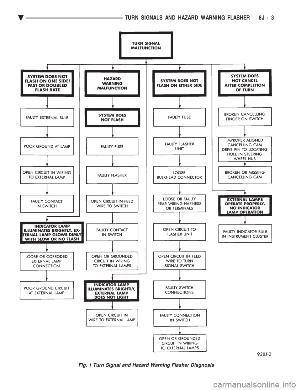
fail, the entire switch assembly must be replaced. Re-
fer to Fig. 1 for diagnosis. To test the switch, first disconnect the negative
battery cable, then remove the upper and lower col-
umn covers to gain access to the switch connector.
Remove switch connector. Using an ohmmeter, test
for continuity (no resistance) between the terminals
of the switch as shown in the following continuity
charts (Fig 2 or 3).
DUAL-FUNCTION SWITCH TESTSÐAG AND AJ BODIES
The dual-function switch contains electrical cir-
cuitry for hazard warning switching, and circuitry
and electronics for turn signal cancellation. The
switch assembly is mounted to the left hand side of
the steering column. To test the hazard warning portion of the switch,
first disconnect the negative battery cable, then re-
move the upper and lower steering column covers to
gain access to the switch connector. Remove switch
connector (Fig. 4). Using an ohmmeter, test for con-
tinuity between the terminals of the switch as shown
in the following continuity chart (Fig. 5). To test the cancellation portion of the switch:
(1) Reconnect battery and switch connector (Fig.
5). (2) Connect voltmeter positive lead (+) to pin 8
and negative lead (-) to ground. (3) Place ignition switch to the ON position. Volt-
meter should read battery voltage. If no voltage is
present, check feed wire to pin 8. If battery voltage is
present continue with switch test.
RIGHT CANCELLATION TEST (1) Connect one side of a jumper wire to pin 3 and
the other end of jumper wire to ground. (2) Connect the positive lead (+) of a voltmeter to
pin 5 and the negative lead (-) to ground.
CAUTION: Do not allow pin 5 to become grounded
during test, switch failure will result.
(3) With the ignition switch in the ON position,
push the cancellation pawl down and read the volt-
meter. (4) The voltmeter should show at least 9 volts. (5) If voltage is 0 to 8 volts the cancellation switch
is defective. If voltage is 9 volts or more the cancel-
lation switch is working correctly.
LEFT CANCELLATION TEST
(1) Connect one side of a jumper wire to pin 4 and
the other end of jumper wire to ground. (2) Connect the positive lead (+) of a voltmeter to
pin 5 and the negative lead (-) to ground.
CAUTION: Do not allow pin 5 to become grounded
during test, switch failure will result.
(3) With the ignition switch in the ON position,
push the cancellation pawl up and read the voltme-
ter. (4) The voltmeter should show at least 9 volts.
(5) If voltage is 0 to 8 volts the cancellation switch
is defective. If voltage is 9 volts or more the cancel-
lation switch is working correctly.
REMOTE TURN SIGNAL SWITCH TESTÐAA AND AJ BODIES
The remote turn signal switch is located on the left
side of the instrument panel switch pod. To test, re-
move switch pod assembly from instrument panel.
Using an ohmmeter, test for continuity between the
terminals of the switch as shown in the following
continuity chart (Fig. 6). The white 7 way connector
next to the 14 way connector must be connected
when performing continuity checks.
CANCELLATION SOLENOID TESTÐAG AND AJ BODIES
To test the turn signal cancellation solenoid:
(1) Remove switch pod from instrument panel.
(2) Connect one end of a jumper wire to the posi-
tive terminal of the battery, the other end to pin 6 of
the turn signal switch 14 way connector. (3) Place turn signal switch in the left turn mode.
(4) Take a second jumper wire and connect one end
to a good ground. Momentarily touch the other end of
the jumper wire to pin 11 or 14. The solenoid should
energize, and return the switch to its center OFF po-
sition. (5) Place turn signal switch in the right turn
mode. (6) Repeat step 4. The solenoid should energize,
and return the switch to its center OFF position. (7) If switch does not return to center in either di-
rection, the switch is defective.
MULTI-FUNCTION SWITCHÐAA, AC, AP AND AY
BODIES
REMOVAL
(1) Disconnect negative battery cable.
(2) Tilt column only remove tilt lever.
8J - 2 TURN SIGNALS AND HAZARD WARNING FLASHER Ä
Page 615 of 2438

Fig. 1 Turn Signal and Hazard Warning Flasher Diagnosis
Ä TURN SIGNALS AND HAZARD WARNING FLASHER 8J - 3