1993 CHEVROLET DYNASTY turn signal
[x] Cancel search: turn signalPage 662 of 2438
PARK AND TURN SIGNAL LAMP OR BULB
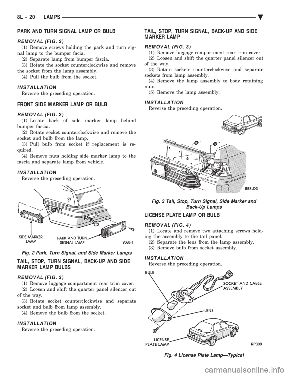
REMOVAL (FIG. 2)
(1) Remove screws holding the park and turn sig-
nal lamp to the bumper facia. (2) Separate lamp from bumper fascia.
(3) Rotate the socket counterclockwise and remove
the socket from the lamp assembly. (4) Pull the bulb from the socket.
INSTALLATION
Reverse the preceding operation.
FRONT SIDE MARKER LAMP OR BULB
REMOVAL (FIG. 2)
(1) Locate back of side marker lamp behind
bumper fascia. (2) Rotate socket counterclockwise and remove the
socket and bulb from the lamp. (3) Pull bulb from socket if replacement is re-
quired. (4) Remove nuts holding side marker lamp to the
fascia and separate lamp from vehicle.
INSTALLATION
Reverse the preceding operation.
TAIL, STOP, TURN SIGNAL, BACK-UP AND SIDE
MARKER LAMP BULBS
REMOVAL (FIG. 3)
(1) Remove luggage compartment rear trim cover.
(2) Loosen and shift the quarter panel silencer out
of the way. (3) Rotate socket counterclockwise and separate
socket and bulb from lamp assembly. (4) Remove the bulb from the socket.
INSTALLATION
Reverse the preceding operation.
TAIL, STOP, TURN SIGNAL, BACK-UP AND SIDE
MARKER LAMP
REMOVAL (FIG. 3)
(1) Remove luggage compartment rear trim cover.
(2) Loosen and shift the quarter panel silencer out
of the way. (3) Rotate sockets counterclockwise and separate
sockets from lamp assembly. (4) Remove the lamp assembly to body retaining
nuts. (5) Remove the lamp assembly.
INSTALLATION
Reverse the preceding operation.
LICENSE PLATE LAMP OR BULB
REMOVAL (FIG. 4)
(1) Locate and remove two attaching screws hold-
ing the assembly to the tail panel. (2) Separate the lens from the lamp assembly.
(3) Remove bulb from socket assembly.
INSTALLATION
Reverse the preceding operation.
Fig. 2 Park, Turn Signal, and Side Marker Lamps
Fig. 3 Tail, Stop, Turn Signal, Side Marker and Back-Up Lamps
Fig. 4 License Plate LampÐTypical
8L - 20 LAMPS Ä
Page 664 of 2438
EXTERIOR LAMPSÐAY-BODY INDEX
page page
Center High Mounted Stop Lamp ............ 24
Center High Mounted Stop Lamp Bulb (CHMSL) . 24
Cornering Lamp or BulbÐAY/C-P-Body ........ 24
Front Side Marker BulbÐAY/C-P-Body ........ 23
Front Side Marker LampÐAY/C-P-Body ....... 23
General Information ....................... 22
Headlamp Diagnosis ...................... 22 Headlamps
............................. 22
License Plate Lamp or BulbÐAY/C-P-Body ..... 24
Park, Turn Signal Lamp or BulbÐAY/C-P-Body . . 22
Sealed Beam ........................... 22
Tail, Stop, Turn Signal, Side Marker and Back-Up Lamp or BulbÐAY/C-P-Body .............. 24
GENERAL INFORMATION
To service exterior lamps on AY/C-S-Body, refer to
procedures covered in Exterior LampsÐAC-Body sec-
tion. AC/C-S-Body uses the same lamps as AY/C-S-
Body.
HEADLAMPS
Conventional and halogen sealed beams are inter-
changeable, It is not recommended that they be
mixed. The lens, filament and reflector of sealed
beams are molded into one unit.
HEADLAMP DIAGNOSIS
For headlamp diagnosis, refer to the headlamp di-
agnosis chart at the beginning of this Group. Refer to
Wiring Diagrams manual for circuit and component
locations.
SEALED BEAM
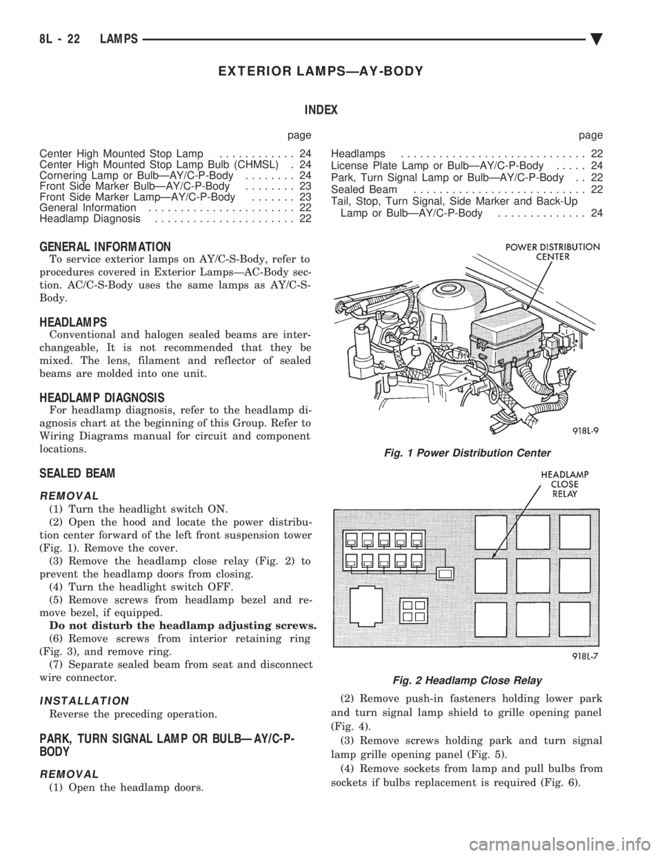
REMOVAL
(1) Turn the headlight switch ON.
(2) Open the hood and locate the power distribu-
tion center forward of the left front suspension tower
(Fig. 1). Remove the cover. (3) Remove the headlamp close relay (Fig. 2) to
prevent the headlamp doors from closing. (4) Turn the headlight switch OFF.
(5) Remove screws from headlamp bezel and re-
move bezel, if equipped. Do not disturb the headlamp adjusting screws.
(6) Remove screws from interior retaining ring
(Fig. 3), and remove ring. (7) Separate sealed beam from seat and disconnect
wire connector.
INSTALLATION
Reverse the preceding operation.
PARK, TURN SIGNAL LAMP OR BULBÐAY/C-P-
BODY
REMOVAL
(1) Open the headlamp doors. (2) Remove push-in fasteners holding lower park
and turn signal lamp shield to grille opening panel
(Fig. 4). (3) Remove screws holding park and turn signal
lamp grille opening panel (Fig. 5). (4) Remove sockets from lamp and pull bulbs from
sockets if bulbs replacement is required (Fig. 6).
Fig. 1 Power Distribution Center
Fig. 2 Headlamp Close Relay
8L - 22 LAMPS Ä
Page 665 of 2438
INSTALLATION
Reverse the preceding operation.
FRONT SIDE MARKER BULBÐAY/C-P-BODY
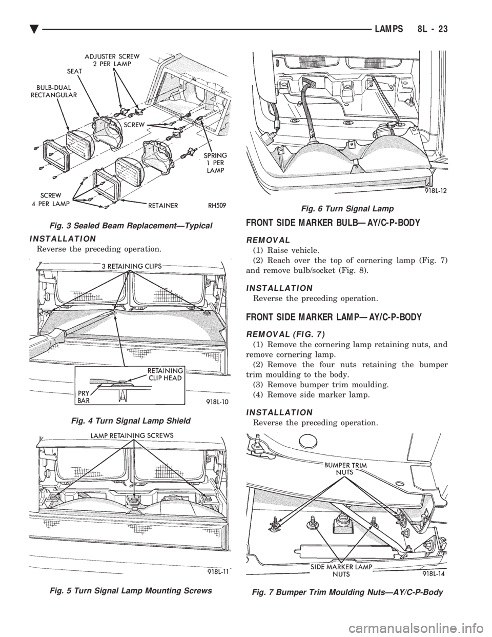
REMOVAL
(1) Raise vehicle.
(2) Reach over the top of cornering lamp (Fig. 7)
and remove bulb/socket (Fig. 8).
INSTALLATION
Reverse the preceding operation.
FRONT SIDE MARKER LAMPÐAY/C-P-BODY
REMOVAL (FIG. 7)
(1) Remove the cornering lamp retaining nuts, and
remove cornering lamp. (2) Remove the four nuts retaining the bumper
trim moulding to the body. (3) Remove bumper trim moulding.
(4) Remove side marker lamp.
INSTALLATION
Reverse the preceding operation.
Fig. 3 Sealed Beam ReplacementÐTypical
Fig. 4 Turn Signal Lamp Shield
Fig. 5 Turn Signal Lamp Mounting Screws
Fig. 6 Turn Signal Lamp
Fig. 7 Bumper Trim Moulding NutsÐAY/C-P-Body
Ä LAMPS 8L - 23
Page 666 of 2438
CORNERING LAMP OR BULBÐAY/C-P-BODY
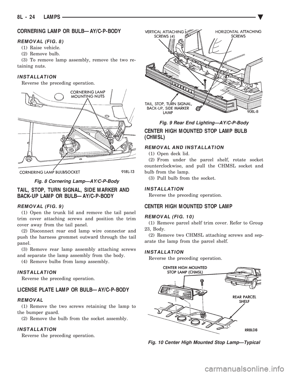
REMOVAL (FIG. 8)
(1) Raise vehicle.
(2) Remove bulb.
(3) To remove lamp assembly, remove the two re-
taining nuts.
INSTALLATION
Reverse the preceding operation.
TAIL, STOP, TURN SIGNAL, SIDE MARKER AND
BACK-UP LAMP OR BULBÐAY/C-P-BODY
REMOVAL (FIG. 9)
(1) Open the trunk lid and remove the tail panel
trim cover attaching screws and position the trim
cover away from the tail panel. (2) Disconnect rear end lamp wire connector and
push the harness grommet outward through the tail
panel. (3) Remove rear lamp assembly attaching screws
and separate the lamp assembly from the body. (4) Remove bulbs from lamp assembly.
INSTALLATION
Reverse the preceding operation.
LICENSE PLATE LAMP OR BULBÐAY/C-P-BODY
REMOVAL
(1) Remove the two screws retaining the lamp to
the bumper guard. (2) Remove the bulb from the socket assembly.
INSTALLATION
Reverse the preceding operation.
CENTER HIGH MOUNTED STOP LAMP BULB
(CHMSL)
REMOVAL AND INSTALLATION
(1) Open deck lid.
(2) From under the parcel shelf, rotate socket
counterclockwise, and pull the CHMSL socket and
bulb from the lamp. (3) Pull bulb from the socket.
INSTALLATION
Reverse the preceding operation.
CENTER HIGH MOUNTED STOP LAMP
REMOVAL (FIG. 10)
(1) Remove parcel shelf trim cover. Refer to Group
23, Body. (2) Remove two CHMSL attaching screws and sep-
arate the lamp from the parcel shelf.
INSTALLATION
Reverse the preceding operation.
Fig. 8 Cornering LampÐAY/C-P-Body
Fig. 9 Rear End LightingÐAY/C-P-Body
Fig. 10 Center High Mounted Stop LampÐTypical
8L - 24 LAMPS Ä
Page 669 of 2438
CONCEALED HEADLAMPS INDEX
page page
Concealed Headlamp MotorÐAC-Body ........ 29
Diagnostic Procedures ..................... 27
General Information ....................... 27 Headlamp DoorÐAC-Body
................. 29
Headlamp DoorÐAY Body ................. 29
Headlamp Drive MotorÐAY Body ............ 30
GENERAL INFORMATION
For proper operation of the Concealed Headlamp
System, refer to the Owner's Manual provided with
the vehicle.
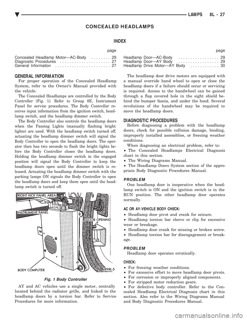
The Concealed Headlamps are controlled by the Body
Controller (Fig. 1). Refer to Group 8E, Instrument
Panel for service procedures. The Body Controller re-
ceives input information from the ignition switch, head-
lamp switch, and the headlamp dimmer switch. The Body Controller also controls the headlamp doors
when the Passing Lights (manually flashing bright
lights) are used. With the headlamp switch turned off,
actuating the headlamp dimmer switch will signal the
Body Controller to open the headlamp doors. The oper-
ator then has two seconds to flash the bright lights be-
fore the Body Controller closes the headlamp doors.
Holding the headlamp dimmer switch in the engaged
position will signal the Body Controller to keep the
headlamp doors open until the dimmer switch is re-
leased. Actuating the headlamp dimmer switch with the
parking lamps ON signals the Body Controller to open
the headlamp doors and keep them open until the head-
lamp switch is turned off.
AY and AC vehicles use a single motor, centrally
located behind the radiator grille, and linked to the
headlamp doors by a torsion bar. Refer to Service
Procedures for more information. The headlamp door drive motors are equipped with
a manual override hand wheel to open or close the
headlamp doors if a failure should occur or servicing
is required. Access to the handwheel can be gained
through a flap covered hole in the sight shield be-
hind the bumper fascia, and under the hood. Several
revolutions of the handwheel may be required to
move the headlamp doors.
DIAGNOSTIC PROCEDURES
Before diagnosing a problem with the headlamp
doors, check for possible collision damage, binding,
improperly installed assemblies, or freezing weather
conditions. When diagnosing an electrical problem, refer to:
² The Concealed Headlamps Electrical Diagnosis
chart in this section.
² The Wiring Diagrams Manual.
² The Headlamp Doors System section of the appro-
priate Body Diagnostic Procedures Manual.
PROBLEM
One headlamp door is inoperative when the head-
lamp switch is ON and the ignition switch is in the
RUN position. The other headlamp door operates
normally.
AC OR AY-VEHICLE BODY CHECK:
² Headlamp door pivot and crank for seizure.
² Headlamp torsion bar sleeve or clip for excessive
wear or breakage.
² Headlamp door crank for missing or broken screw.
² Headlamp torsion bar for disengagement or break-
age.
PROBLEM
Headlamp door operates erratically.
CHECK:
² For freezing weather conditions.
² For excessive effort to move headlamp door pivots.
² For corrosion or improperly aligned components.
² For stripped motor reduction gears.
² For defective body controller. Refer to the Con-
cealed Headlamp Electrical Diagnosis chart in this
section. Also refer to the Wiring Diagrams Manual
and Body Diagnostic Procedures Manual.
Fig. 1 Body Controller
Ä LAMPS 8L - 27
Page 672 of 2438
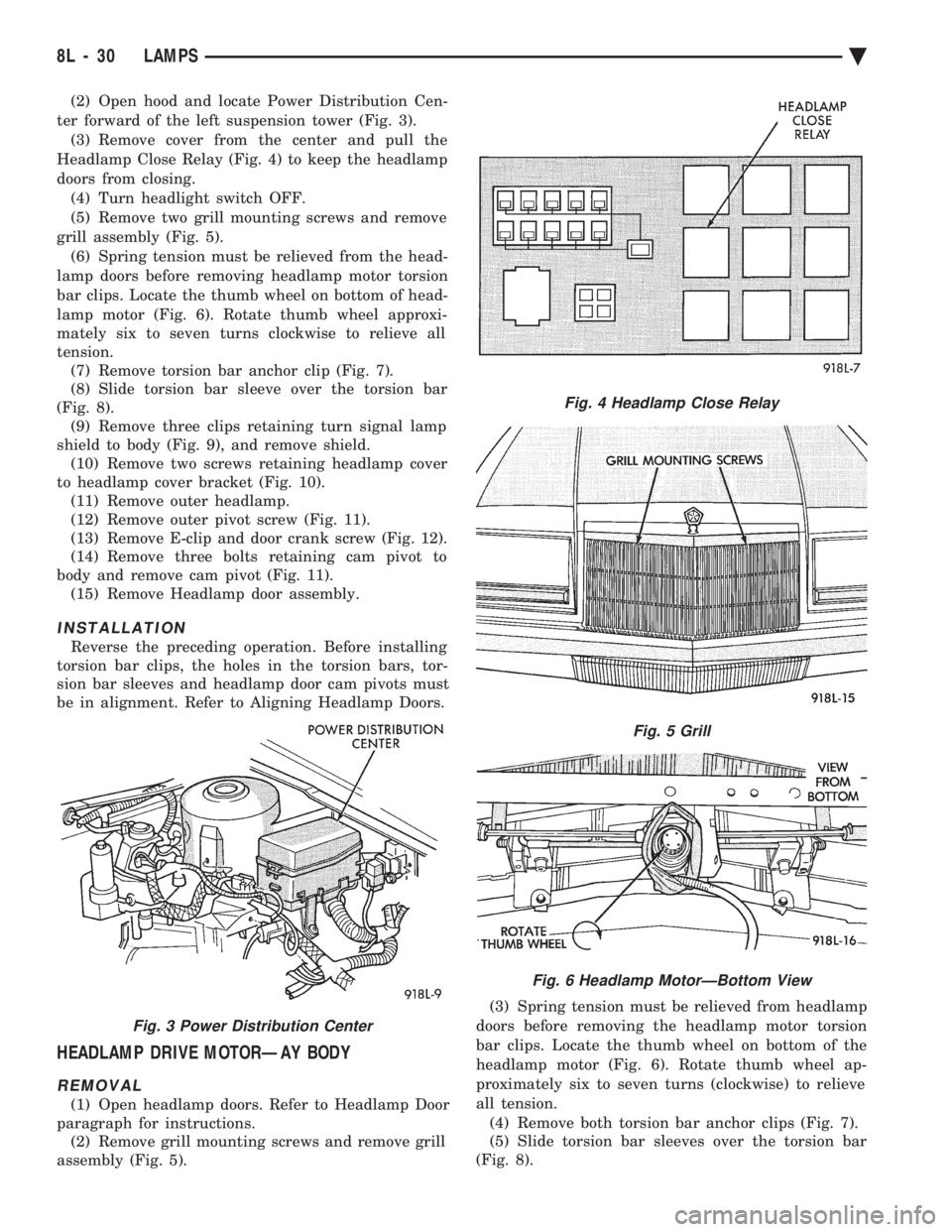
(2) Open hood and locate Power Distribution Cen-
ter forward of the left suspension tower (Fig. 3). (3) Remove cover from the center and pull the
Headlamp Close Relay (Fig. 4) to keep the headlamp
doors from closing. (4) Turn headlight switch OFF.
(5) Remove two grill mounting screws and remove
grill assembly (Fig. 5). (6) Spring tension must be relieved from the head-
lamp doors before removing headlamp motor torsion
bar clips. Locate the thumb wheel on bottom of head-
lamp motor (Fig. 6). Rotate thumb wheel approxi-
mately six to seven turns clockwise to relieve all
tension. (7) Remove torsion bar anchor clip (Fig. 7).
(8) Slide torsion bar sleeve over the torsion bar
(Fig. 8). (9) Remove three clips retaining turn signal lamp
shield to body (Fig. 9), and remove shield. (10) Remove two screws retaining headlamp cover
to headlamp cover bracket (Fig. 10). (11) Remove outer headlamp.
(12) Remove outer pivot screw (Fig. 11).
(13) Remove E-clip and door crank screw (Fig. 12).
(14) Remove three bolts retaining cam pivot to
body and remove cam pivot (Fig. 11). (15) Remove Headlamp door assembly.
INSTALLATION
Reverse the preceding operation. Before installing
torsion bar clips, the holes in the torsion bars, tor-
sion bar sleeves and headlamp door cam pivots must
be in alignment. Refer to Aligning Headlamp Doors.
HEADLAMP DRIVE MOTORÐAY BODY
REMOVAL
(1) Open headlamp doors. Refer to Headlamp Door
paragraph for instructions. (2) Remove grill mounting screws and remove grill
assembly (Fig. 5). (3) Spring tension must be relieved from headlamp
doors before removing the headlamp motor torsion
bar clips. Locate the thumb wheel on bottom of the
headlamp motor (Fig. 6). Rotate thumb wheel ap-
proximately six to seven turns (clockwise) to relieve
all tension. (4) Remove both torsion bar anchor clips (Fig. 7).
(5) Slide torsion bar sleeves over the torsion bar
(Fig. 8).
Fig. 3 Power Distribution Center
Fig. 4 Headlamp Close Relay
Fig. 5 Grill
Fig. 6 Headlamp MotorÐBottom View
8L - 30 LAMPS Ä
Page 673 of 2438
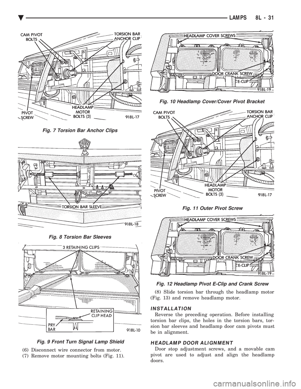
(6) Disconnect wire connector from motor.
(7) Remove motor mounting bolts (Fig. 11). (8) Slide torsion bar through the headlamp motor
(Fig. 13) and remove headlamp motor.
INSTALLATION
Reverse the preceding operation. Before installing
torsion bar clips, the holes in the torsion bars, tor-
sion bar sleeves and headlamp door cam pivots must
be in alignment.
HEADLAMP DOOR ALIGNMENT
Door stop adjustment screws, and a movable cam
pivot are used to adjust and align the headlamp
doors.
Fig. 9 Front Turn Signal Lamp Shield
Fig. 10 Headlamp Cover/Cover Pivot Bracket
Fig. 7 Torsion Bar Anchor Clips
Fig. 8 Torsion Bar Sleeves
Fig. 11 Outer Pivot Screw
Fig. 12 Headlamp Pivot E-Clip and Crank Screw
Ä LAMPS 8L - 31
Page 680 of 2438
BULB APPLICATION TABLE
GENERAL INFORMATION
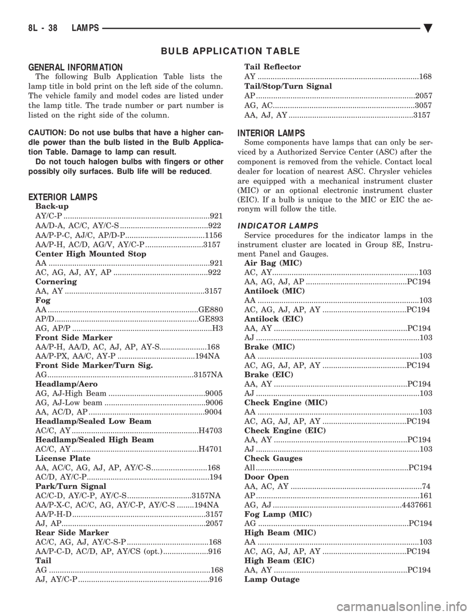
The following Bulb Application Table lists the
lamp title in bold print on the left side of the column.
The vehicle family and model codes are listed under
the lamp title. The trade number or part number is
listed on the right side of the column.
CAUTION: Do not use bulbs that have a higher can-
dle power than the bulb listed in the Bulb Applica-
tion Table. Damage to lamp can result. Do not touch halogen bulbs with fingers or other
possibly oily surfaces. Bulb life will be reduced .
EXTERIOR LAMPS
Back-up
AY/C-P ....................................................................921
AA/D-A, AC/C, AY/C-S .........................................922
AA/P-P-C, AJ/C, AP/D-P.....................................1156
AA/P-H, AC/D, AG/V, AY/C-P ...........................3157
Center High Mounted Stop
AA ...........................................................................921
AC, AG, AJ, AY, AP ............................................922
Cornering
AA, AY .................................................................3157
Fog
AA ......................................................................GE880
AP/D...................................................................GE893
AG, AP/P .................................................................H3
Front Side Marker
AA/P-H, AA/D, AC, AJ, AP, AY-S......................168
AA/P-PX, AA/C, AY-P ....................................194NA
Front Side Marker/Turn Sig.
AG....................................................................3157NA
Headlamp/Aero
AG, AJ-High Beam .............................................9005
AG, AJ-Low beam ...............................................9006
AA, AC/D, AP ......................................................9004
Headlamp/Sealed Low Beam
AC/C, AY ...........................................................H4703
Headlamp/Sealed High Beam
AC/C, AY ...........................................................H4701
License Plate
AA, AC/C, AG, AJ, AP, AY/C-S ..........................168
AC/D, AY/C-P.........................................................194
Park/Turn Signal
AC/C-D, AY/C-P, AY/C-S ..............................3157NA
AA/P-X-C, AC/C, AG, AY/C-P, AY/C-S ........194NA
AA/P-H-D ..............................................................3157
AJ, AP...................................................................2057
Rear Side Marker
AC/C, AG, AJ, AY/C-S-P ......................................168
AA/P-C-D, AC/D, AP, AY/CS (opt.) .....................916
Tail
AG ...........................................................................168
AJ, AY/C-P .............................................................916 Tail Reflector
AY ...........................................................................168
Tail/Stop/Turn Signal
AP ..........................................................................2057
AG, AC..................................................................3057
AA, AJ, AY ..........................................................3157
INTERIOR LAMPS
Some components have lamps that can only be ser-
viced by a Authorized Service Center (ASC) after the
component is removed from the vehicle. Contact local
dealer for location of nearest ASC. Chrysler vehicles
are equipped with a mechanical instrument cluster
(MIC) or an optional electronic instrument cluster
(EIC). If a bulb is unique to the MIC or EIC the ac-
ronym will follow the title.
INDICATOR LAMPS
Service procedures for the indicator lamps in the
instrument cluster are located in Group 8E, Instru-
ment Panel and Gauges. Air Bag (MIC)
AC, AY....................................................................103
AA, AG, AJ, AP ...............................................PC194
Antilock (MIC)
AA ...........................................................................103
AC, AG, AJ, AP, AY .......................................PC194
Antilock (EIC)
AA, AY ..............................................................PC194
AJ ............................................................................103
Brake (MIC)
AA ...........................................................................103
AC, AG, AJ, AP, AY .......................................PC194
Brake (EIC)
AA, AY ..............................................................PC194
AJ ............................................................................103
Check Engine (MIC)
AA ...........................................................................103
AC, AG, AJ, AP, AY .......................................PC194
Check Engine (EIC)
AA, AY ..............................................................PC194
AJ ............................................................................103
Check Gauges
All .......................................................................PC194
Door Open
AA, AC, AY .............................................................74
AP ............................................................................161
AG, AJ ............................................................4437661
Fog Lamp (MIC)
AG ......................................................................PC194
High Beam (MIC)
AA ...........................................................................103
AC, AG, AJ, AP, AY .......................................PC194
High Beam (EIC)
AA, AY ..............................................................PC194
Lamp Outage
8L - 38 LAMPS Ä